EP1329702A1 - Polarization effect averaging - Google Patents
Polarization effect averaging Download PDFInfo
- Publication number
- EP1329702A1 EP1329702A1 EP02018761A EP02018761A EP1329702A1 EP 1329702 A1 EP1329702 A1 EP 1329702A1 EP 02018761 A EP02018761 A EP 02018761A EP 02018761 A EP02018761 A EP 02018761A EP 1329702 A1 EP1329702 A1 EP 1329702A1
- Authority
- EP
- European Patent Office
- Prior art keywords
- polarization
- property
- dut
- wavelength
- optical property
- Prior art date
- Legal status (The legal status is an assumption and is not a legal conclusion. Google has not performed a legal analysis and makes no representation as to the accuracy of the status listed.)
- Granted
Links
- 230000010287 polarization Effects 0.000 title claims abstract description 133
- 238000012935 Averaging Methods 0.000 title abstract description 20
- 230000003287 optical effect Effects 0.000 claims abstract description 81
- 238000000034 method Methods 0.000 claims abstract description 26
- 238000012360 testing method Methods 0.000 claims abstract description 26
- 230000001419 dependent effect Effects 0.000 claims abstract description 16
- 239000011159 matrix material Substances 0.000 claims description 16
- 238000012545 processing Methods 0.000 claims description 13
- 230000004044 response Effects 0.000 claims description 11
- 230000003247 decreasing effect Effects 0.000 claims description 4
- 238000003780 insertion Methods 0.000 claims description 2
- 230000037431 insertion Effects 0.000 claims description 2
- 238000005259 measurement Methods 0.000 description 50
- 208000032005 Spinocerebellar ataxia with axonal neuropathy type 2 Diseases 0.000 description 17
- 208000033361 autosomal recessive with axonal neuropathy 2 spinocerebellar ataxia Diseases 0.000 description 17
- 101150004026 SOP1 gene Proteins 0.000 description 8
- 101100508810 Saccharomyces cerevisiae (strain ATCC 204508 / S288c) INP53 gene Proteins 0.000 description 8
- 101100366622 Saccharomyces cerevisiae (strain ATCC 204508 / S288c) SRO7 gene Proteins 0.000 description 8
- 101100366621 Saccharomyces cerevisiae (strain ATCC 204508 / S288c) SRO77 gene Proteins 0.000 description 8
- 101100217143 Schizosaccharomyces pombe (strain 972 / ATCC 24843) arc1 gene Proteins 0.000 description 8
- 101150083500 sop-2 gene Proteins 0.000 description 8
- 230000005540 biological transmission Effects 0.000 description 4
- 230000010355 oscillation Effects 0.000 description 2
- 230000004069 differentiation Effects 0.000 description 1
- 239000006185 dispersion Substances 0.000 description 1
- 239000000835 fiber Substances 0.000 description 1
- 230000001771 impaired effect Effects 0.000 description 1
- 230000006855 networking Effects 0.000 description 1
- 230000009467 reduction Effects 0.000 description 1
- 238000002310 reflectometry Methods 0.000 description 1
- 230000000630 rising effect Effects 0.000 description 1
- 230000001960 triggered effect Effects 0.000 description 1
Images


Classifications
-
- G—PHYSICS
- G01—MEASURING; TESTING
- G01M—TESTING STATIC OR DYNAMIC BALANCE OF MACHINES OR STRUCTURES; TESTING OF STRUCTURES OR APPARATUS, NOT OTHERWISE PROVIDED FOR
- G01M11/00—Testing of optical apparatus; Testing structures by optical methods not otherwise provided for
- G01M11/30—Testing of optical devices, constituted by fibre optics or optical waveguides
- G01M11/33—Testing of optical devices, constituted by fibre optics or optical waveguides with a light emitter being disposed at one fibre or waveguide end-face, and a light receiver at the other end-face
-
- G—PHYSICS
- G01—MEASURING; TESTING
- G01J—MEASUREMENT OF INTENSITY, VELOCITY, SPECTRAL CONTENT, POLARISATION, PHASE OR PULSE CHARACTERISTICS OF INFRARED, VISIBLE OR ULTRAVIOLET LIGHT; COLORIMETRY; RADIATION PYROMETRY
- G01J9/00—Measuring optical phase difference; Determining degree of coherence; Measuring optical wavelength
- G01J9/02—Measuring optical phase difference; Determining degree of coherence; Measuring optical wavelength by interferometric methods
-
- G—PHYSICS
- G01—MEASURING; TESTING
- G01M—TESTING STATIC OR DYNAMIC BALANCE OF MACHINES OR STRUCTURES; TESTING OF STRUCTURES OR APPARATUS, NOT OTHERWISE PROVIDED FOR
- G01M11/00—Testing of optical apparatus; Testing structures by optical methods not otherwise provided for
- G01M11/30—Testing of optical devices, constituted by fibre optics or optical waveguides
- G01M11/33—Testing of optical devices, constituted by fibre optics or optical waveguides with a light emitter being disposed at one fibre or waveguide end-face, and a light receiver at the other end-face
- G01M11/331—Testing of optical devices, constituted by fibre optics or optical waveguides with a light emitter being disposed at one fibre or waveguide end-face, and a light receiver at the other end-face by using interferometer
-
- G—PHYSICS
- G01—MEASURING; TESTING
- G01J—MEASUREMENT OF INTENSITY, VELOCITY, SPECTRAL CONTENT, POLARISATION, PHASE OR PULSE CHARACTERISTICS OF INFRARED, VISIBLE OR ULTRAVIOLET LIGHT; COLORIMETRY; RADIATION PYROMETRY
- G01J4/00—Measuring polarisation of light
Definitions
- the present invention is related to the determination of an optical property of a light beam, e.g. received from device under test.
- the state of polarization of an incident light, or of a part thereof is set by means of a first polarization controller.
- a first polarized output with at least two different states of polarization is obtained.
- the polarized light is forwarded to a first determination unit, which determines, for each of said at least two different states of polarization, a first optical property.
- a mean value of the optical property values for said at least two different states of polarization, or of a property derived therefrom, is determined by a processing unit, in order to eliminate any polarization dependent measurement error.
- optical property determination shows some kind of polarization dependence, and therefore, the state of polarization of the incident light affects the result of the measurement.
- interferometric devices that generate an interference pattern by splitting up the incoming light into different light paths cause polarization dependent measurement errors.
- the invention is not limited to interferometric devices, though. Different polarization states are generated on purpose in the optical property determination path, and then, an averaging procedure is performed. This simple solution leads to a considerable reduction of measurement errors. This concept can be applied both to single measurements and to repeated measurements of said first optical property.
- the apparatus comprises a second determination unit for receiving a response signal of a device under test, whereby said response signal is obtained in response to a signal derived from said incident light. From said response signal, a first DUT property of the device under test is determined. The first DUT property represents an optical property of the DUT. Both the first optical property and the first DUT property are forwarded to a processing unit, which is adapted for determining an averaged DUT property from the first DUT property and the first optical property.
- the processing unit determines a mean value of at least one of: the first optical property determined for said at least two states of polarization, or a property derived from the first optical property as well as from the first DUT property for each of said at least two states of polarization.
- the apparatus comprises a light path for a device under test in addition to the optical property determination path.
- a first DUT property is determined.
- the optical property determination path is used as a reference when determining said first DUT property.
- the optical property values are impaired by a polarization dependent error, and said error is transformed in a DUT property measurement error.
- This DUT-parameter measurement error can be eliminated or at least reduced by averaging at least one of: the first optical property determined for said at least two states of polarization, or a property derived from the first optical property as well as from the first DUT property for said at least two states of polarization.
- the measurement set-up according to the second embodiment of the invention is very versatile and can be used for the determination of any property of the device under test, for example for the determination of transmission or reflectivity of the device under test, or for the determination of the Jones matrix of the device under test.
- the measurements for the different states of polarization do not have to be performed consecutively.
- By means of a beam splitter it is possible to perform the measurements for different states of polarization in parallel, and the measurement time is kept small.
- the first optical property determined by said first determination unit is the wavelength of the incident light.
- a light path for determining said first DUT property and a wavelength determination path it is possible to obtain said first DUT property as a function of wavelength.
- Said wavelength, or a property derived therefrom, is determined for at least two different states of polarization, and by performing an averaging operation, the polarization dependent error is decreased.
- the incident light is generated by a tunable light source, and preferably, said light source performs wavelength sweeps over a whole range of wavelengths. This allows to study device properties in dependence on the wavelength.
- the polarization is set to a first state of polarization during the first wavelength sweep, to a second state of polarization during the second wavelength sweep, etc.
- the state of polarization of the polarization controller is set to the next state of polarization.
- the state of polarization is not changed, and therefore, the measurements are simplified.
- the wavelength is changed over time during a wavelength sweep, and the first optical property is measured for discrete points of time.
- the measurement device might comprise an internal clock that triggers the wavelength measurement.
- the values of the first DUT property determined in the light path that comprises the device under test are related to corresponding values of the first optical property.
- a DUT property value measured at a certain time is related to a value of the first optical property determined at the same time for a certain state of polarization.
- the first DUT parameter of the device under test which has been recorded as a function of time, is now known as a function of the first optical property, e.g. as a function of wavelength or frequency of the incident light, or of any other optical property that can serve as a reference for said DUT parameter measurements.
- a first dependency of said first DUT property on the respective optical property is obtained for the first state of polarization
- a second dependency of said DUT property on the optical property is obtained for the second state of polarization, etc.
- the averaging is performed by determining the average of DUT property values that correspond to the same value of the first optical property.
- the averaging is performed with respect to said first optical property, and not with respect to time.
- said tunable light source performs wavelength sweeps, it does no longer matter whether the wavelength sweeps performed for said first and said second state of polarization are coincident or not.
- the accuracy of the wavelength sweeps is no longer important, because the first DUT property of the device under test is related to said first optical property, e.g. to the wavelength, to the frequency, or to any other optical property. This means that the requirements concerning the accuracy of the wavelength sweeps performed by the tunable light source can be lowered.
- both the values of said first DUT property and the values of said first optical property are determined regularly, at discrete instants of time.
- the measurements both in the light path comprising the DUT and in the light path for determining the first optical property might be triggered by a common clocking circuit.
- the measurement set-up comprises two polarization controllers, one for the optical property determination path, and one for the light path comprising the DUT.
- the states of polarization in said two light paths can be controlled independently. This allows to vary the state of polarization in the optical property determination path, while the state of polarization in the light path of the device under test is kept constant.
- the first DUT property can therefore be measured with respect to a substantially constant state of polarization within the light path of the DUT.
- the measurement set-up comprises only one polarization controller both for the optical property determination path and for the light path of the DUT, the light in both light paths is polarized in the same way.
- the Jones matrix which describes the transmission properties of a device under test
- a simple measurement set-up is sufficient.
- the Differential Group Delay (DGD) of a device under test can be obtained.
- the Differential Group Delay is a measure for the polarization dependent dispersion of the device under test.
- the concept according to one of the above embodiments can be partly or entirely embodied or supported by one or more suitable software programs, which can be stored on or otherwise provided by any kind of data carrier, and which might be executed in or by any suitable data processing unit.
- Software programs or routines are preferably applied for instrument control and calculation of device properties and wavelength.
- the measurement set-up comprises a tunable laser source 1 which generates monochromatic light 2 of a wavelength ⁇ true .
- the tunable laser source 1 is capable of performing a wavelength sweep over time, whereby the wavelength ⁇ true is increased in a nearly linear way as a function of time: ⁇ true (t) ⁇ t
- the monochromatic light 2 is forwarded to a polarization controller 3, which sets the polarization of said monochromatic light 2 to a well-defined state of polarization (SOP).
- SOP state of polarization
- monochromatic light 4 with a well-defined state of polarization is obtained.
- the wavelength of said light is measured by means of a wavelength determination unit 5, which might comprise an interferometric device such as a Michelson-interferometer or a Mach-Zehnder-interferometer.
- the wavelength is determined by analyzing the interference pattern, for example by counting the interference fringes.
- the measured wavelength ⁇ and(kT) is obtained at discrete instants k ⁇ T of time, whereby k is a natural number.
- the measured wavelength ⁇ and( ⁇ true , SOP1) is shown as a function of the true wavelength ⁇ true for a first state of polarization SOP1.
- the measured wavelength ⁇ and( ⁇ true , SOP2) is shown as a function of ⁇ true for a second state of polarization SOP2.
- an interferometric measurement set-up for the determination of wavelengths causes an oscillating error that is superimposed on the true wavelength and that depends both on the state of polarization (SOP) and on the wavelength itself.
- the error ⁇ error is periodical over both polarization and wavelength; its mean value is equal to zero.
- the polarization dependent wavelength error ⁇ error can be reduced by averaging over at least two wavelength sweeps, whereby a different state of polarization is used during each of the at least two wavelength sweeps.
- the averaged wavelength is shown as a function of the true wavelength ⁇ true . If the oscillating wavelength error in Fig. 2A is sufficiently out of phase compared to the oscillating wavelength error in Fig. 2B, the wavelength error of the averaged wavelength is significantly reduced. For this reason, ⁇ and AVERAGED ⁇ ⁇ true .
- the inventive concept of reducing measurement inaccuracy by averaging over several measurements with different states of polarization is not only applicable to wavelength sweeps, but also to single wavelength measurements.
- the averaging over at least two states of polarization can be performed for a single wavelength.
- a second embodiment of the invention is shown.
- an optical parameter ⁇ of a device under test (DUT) is measured as a function of wavelength.
- the measurement set-up shown in Fig. 3 comprises a wavelength determination path 6 and a light path 7 for the device under test.
- Monochromatic light 9 from a tunable laser source 8 is forwarded both to a polarization controller 10 for the wavelength determination path 6 and to a polarization controller 11 for the light path 7.
- the tunable laser source 8 performs wavelength sweeps; the wavelength of the laser light is continuously increased or decreased over a range of wavelengths as a function of time.
- the polarization controller 10 sets the state of polarization SOP WRU for the wavelength determination path 6 and generates polarized light 12.
- the wavelength of the polarized light 12 is determined. This can be done by means of an interferometric device, for example by means of a Michelson-interferometer or a Mach-Zehnder-interferometer.
- the wavelength is determined in regular time intervals at discrete instants of time k ⁇ T.
- the measured wavelength ⁇ and(kT, SOP WRU ) is obtained.
- the measured wavelength ⁇ and(kT, SOP WRU ) depends both on the measurement time k.T and on the state of polarization SOP WRU .
- the measured wavelength ⁇ and(kT, SOP WRU ) is forwarded to the processing unit 14.
- the polarization controller 11 sets the state of polarization SOP DUT for the light path 7.
- two separate polarization controllers 10 and 11 are used for the wavelength determination path 6 and for the light path 7, and therefore, the state of polarization SOP WRU in the wavelength determination path 6 can be varied independently of the state of polarization SOP DUT in the light path 7.
- polarized light 15 with a state of polarization SOP DUT is obtained, which is forwarded to a sensor unit box 16.
- the sensor unit box 16 contains the device under test 17 and determines the optical parameter ⁇ and of said device under test 17.
- the optical parameter ⁇ and is measured synchronously with the wavelength ⁇ and(kT, SOP WRU ) at the same discrete instants of time k ⁇ T.
- the obtained measurement values ⁇ and(kT, SOP DUT ) are forwarded to the processing unit 14, which relates each of said values ⁇ and(kT, SOP DUT ) to a wavelength value ⁇ and(kT, SOP WRU ) corresponding to the same k.T.
- the polarization SOP WRU in the wavelength determination path 6 is set to a different state.
- the state of polarization SOP DUT in the light path 7 remains constant during all these wavelength sweeps.
- ⁇ error the average of the various functions recorded for different SOP WRU is calculated. The measurement inaccuracy is considerably reduced by averaging the optical parameter ⁇ and over different states of polarization SOP WRU .
- Fig. 4A and 4B show how this averaging procedure is performed.
- ⁇ and(kT, SOP WRU ) is depicted as a function of time k.T for two different states of polarization SOP WRU 1 and SOP WRU 2.
- SOP WRU 1 the state of polarization in the wavelength determination path 6
- SOP WRU 2 the state of polarization in the wavelength determination path 6
- the measured wavelengths ⁇ and(kT, SOP WRU 1) and ⁇ and(kT, SOP WRU 2) are out of phase.
- the wavelength measured for ⁇ and(kT, SOP WRU 1) at the measurement point 18 is smaller than ⁇ true , which means that there is a negative wavelength error.
- the wavelength measured for ⁇ and(kT, SOP WRU 2) is larger than the true wavelength ⁇ true , and there is a positive wavelength error.
- the optical parameter ⁇ and is measured in the sensor unit box 16, and a measurement value ⁇ and(kT, SOP DUT ) is obtained.
- ⁇ and(kT, SOP DUT ) is obtained.
- ⁇ and(kT, SOP DUT ) is interested in the wavelength dependence of ⁇ and, and not in the time dependence of ⁇ and, because the way ⁇ and depends on the time depends on how the respective wavelength sweep is performed.
- the measured parameter value ⁇ and(3T, SOP DUT ) is related to the corresponding wavelength value measured at this instant of time, in our example to ⁇ and(3T, SOP WRU ).
- Fig. 4B the thus obtained dependencies of ⁇ and on ⁇ and are shown for two different states of polarization SOP WRU 1 and SOP WRU 2.
- the measurement point 18 is obtained.
- the measurement point 19 is obtained.
- the processing unit 14 calculates the arithmetic means of and The averaged DUT-parameter is obtained, which gives a dependency of the averaged DUT-parameter ⁇ and AVERAGED on ⁇ and and SOP DUT .
- the averaging procedure is no longer performed with respect to time, but with respect to wavelength.
- the measurement points 20 and 21 correspond to the same wavelength ⁇ and.
- the averaged point 22 is obtained by averaging the value ⁇ and of point 20 and of point 21.
- the measurement points 20 and 21 have not been recorded at the same time, though.
- Measurement point 20 has been recorded at a time t > 3T, and measurement point 21 has been recorded at a time t ⁇ 3T. Therefore, the averaging procedure is no longer performed with respect to values of ⁇ and that correspond to the same time t, but with respect to values of ⁇ and that correspond to the same wavelength.
- the time dependency of the wavelength sweeps is no longer important for this kind of averaging procedure, and therefore, the requirements concerning the accuracy of the wavelength sweeps can be considerably reduced.
- a tunable laser source 23 emits monochromatic light 24 and performs wavelength sweeps, whereby the state of polarization (SOP) of said monochromatic light 24 is set by the polarization controller 25.
- the set-up shown in Fig. 5 comprises only one single polarization controller 25, which sets the state of polarization both for the wavelength determination path 26 and for the optical parameter determination path 27. This is the main difference between the third embodiment shown in Fig. 5 and the second embodiment shown in Fig. 3.
- the states of polarization SOP WRU and SOP DUT can be set independently from each other, in the third embodiment, there is only one state of polarization SOP for both the wavelength determination path 26 and the optical parameter determination path 27.
- certain types of optical measurements such as the determination of the Jones matrix and of the Differential Group Delay (DGD), this is sufficient.
- Light 28 with a well-defined state of polarization is forwarded to the wavelength reference unit 29, in order to determine, in regular time intervals, the wavelength.
- the wavelength reference unit 29 might comprise interferometric devices as described above.
- the measured wavelength ⁇ and(kT, SOP), which depends on the state of polarization SOP, is forwarded to the processing unit 30.
- the optical parameter determination path 27 comprises a sensor unit box 31 that contains a device under test (DUT) 32.
- the sensor unit box 31 might for example determine the horizontal component I tx as well as the vertical component I ty of the light intensity transmitted through the device under test 32. In this case, both the horizontal component 33 and the vertical component 34 of the intensity are forwarded to the processing unit 30.
- the Jones matrix describes how the device under test transforms an incident light wave into a transmitted light wave :
- the parameters a 11 ( ⁇ ), a 12 ( ⁇ ), a 21 ( ⁇ ), a 22 ( ⁇ ) are complex parameters that vary as a function of ⁇ .
- the first wavelength scan "Scan1" comprises a first wavelength sweep with a state of polarization SOP1, and a second wavelength sweep with a state of polarization SOP2, whereby the state of polarization SOP2 is orthogonal to SOP1.
- Scan1 comprises a first wavelength sweep with a state of polarization SOP1
- second wavelength sweep with a state of polarization SOP2, whereby the state of polarization SOP2 is orthogonal to SOP1.
- both the horizontal component 33 and the vertical component 34 of the transmitted intensity are determined.
- the complex matrix elements a 11 ( ⁇ ), a 12 ( ⁇ ), a 21 ( ⁇ ), a 22 ( ⁇ ) of the Jones matrix J can be calculated as a function of wavelength ⁇ .
- JME Jones Matrix Eigenvalue
- the second wavelength scan "Scan2" also comprises two wavelength sweeps.
- the states of polarization are shifted by a parameter ⁇ . Therefore, during the first wavelength sweep of Scan2, the state of polarization is SOP1+ ⁇ . During the second wavelength sweep of Scan2, the state of polarization is SOP2+ ⁇ .
- the data recorded during the two wavelength sweeps of Scan2 allows to determine all the complex matrix elements of the Jones matrix A as a function of ⁇ .
- JME Jones Matrix Eigenvalue
- the Eigenvalues EV1, EV2 of J'J -1 can be used for calculating the Differential Group Delay (DGD), which is defined as the difference of the imaginary parts of said two Eigenvalues.
- DGD( ⁇ , Scan1) is equal to Im(EV1( ⁇ , Scan1) - EV2( ⁇ , Scan1)).
- the Differential Group Delay DGD( ⁇ , Scan2) is obtained as Im(EV1( ⁇ , Scan2) - EV2( ⁇ , Scan2)).
- Fig. 6A the Differential Group Delay DGD( ⁇ , Scan1) determined from Scan1 is shown as a function of ⁇ .
- Fig. 6B depicts the Differential Group Delay DGD( ⁇ , Scan2) determined from Scan2 as a function of ⁇ . It can be seen that both for DGD( ⁇ , Scan1) and for DGD( ⁇ , Scan2), there is an oscillating error superimposed on the Differential Group Delay that depends on the states of polarization during the wavelength sweeps of Scan1 and Scan2. The oscillations are out of phase, and therefore, the error can be reduced by performing an averaging procedure.
- Fig. 6C the averaged Differential Group Delay DGD AVERAGED ( ⁇ ) is shown as a function of wavelength.
- a measurement set-up of the kind shown in Fig. 5 allows to considerably reduce polarization dependent error.
- the Jones matrix can be used for calculating the polarization dependent insertion loss characteristics (average loss and polarization dependent loss, PDL) and the Group Delay (GD) characteristic of the DUT.
Landscapes
- Physics & Mathematics (AREA)
- General Physics & Mathematics (AREA)
- Optics & Photonics (AREA)
- Chemical & Material Sciences (AREA)
- Analytical Chemistry (AREA)
- Spectroscopy & Molecular Physics (AREA)
- Testing Of Optical Devices Or Fibers (AREA)
Abstract
Description
- The present invention is related to the determination of an optical property of a light beam, e.g. received from device under test.
- Because of the large transmission bandwidth of fiber optical components, such components are of rising importance for the implementation of networking backbones, for example for the internet. For these applications, accurate measuring techniques for determining optical properties such as polarization dependent transmission, Differential Group Delay, etc. are required. A lot of optical properties have to be measured as a function of wavelength. In order to obtain reliable results, both the wavelength itself and the respective optical property have to be determined with high accuracy.
- It is an object of the invention to provide an improved determination of an optical property of a light beam. The object is solved by the independent claims. Preferred embodiments are shown by the dependent claims.
- According to a first embodiment of the invention, the state of polarization of an incident light, or of a part thereof, is set by means of a first polarization controller. A first polarized output with at least two different states of polarization is obtained. The polarized light is forwarded to a first determination unit, which determines, for each of said at least two different states of polarization, a first optical property. A mean value of the optical property values for said at least two different states of polarization, or of a property derived therefrom, is determined by a processing unit, in order to eliminate any polarization dependent measurement error.
- Many types of optical property determination show some kind of polarization dependence, and therefore, the state of polarization of the incident light affects the result of the measurement. Especially, but not only, interferometric devices that generate an interference pattern by splitting up the incoming light into different light paths cause polarization dependent measurement errors. The invention is not limited to interferometric devices, though. Different polarization states are generated on purpose in the optical property determination path, and then, an averaging procedure is performed. This simple solution leads to a considerable reduction of measurement errors. This concept can be applied both to single measurements and to repeated measurements of said first optical property.
- According to a second embodiment of the invention, the apparatus comprises a second determination unit for receiving a response signal of a device under test, whereby said response signal is obtained in response to a signal derived from said incident light. From said response signal, a first DUT property of the device under test is determined. The first DUT property represents an optical property of the DUT. Both the first optical property and the first DUT property are forwarded to a processing unit, which is adapted for determining an averaged DUT property from the first DUT property and the first optical property. For this purpose, the processing unit determines a mean value of at least one of: the first optical property determined for said at least two states of polarization, or a property derived from the first optical property as well as from the first DUT property for each of said at least two states of polarization.
- In the second embodiment of the invention, the apparatus comprises a light path for a device under test in addition to the optical property determination path. By means of a second determination unit, a first DUT property is determined. The optical property determination path is used as a reference when determining said first DUT property. But the optical property values are impaired by a polarization dependent error, and said error is transformed in a DUT property measurement error. This DUT-parameter measurement error can be eliminated or at least reduced by averaging at least one of: the first optical property determined for said at least two states of polarization, or a property derived from the first optical property as well as from the first DUT property for said at least two states of polarization. By recording measurements for at least two different states of polarization, and by performing an averaging over said at least two states of polarization, it is possible to reduce or even eliminate the polarization dependent error.
- The measurement set-up according to the second embodiment of the invention is very versatile and can be used for the determination of any property of the device under test, for example for the determination of transmission or reflectivity of the device under test, or for the determination of the Jones matrix of the device under test. The measurements for the different states of polarization do not have to be performed consecutively. By means of a beam splitter, it is possible to perform the measurements for different states of polarization in parallel, and the measurement time is kept small.
- According to a preferred embodiment of the invention, the first optical property determined by said first determination unit is the wavelength of the incident light. By providing two light paths, a light path for determining said first DUT property and a wavelength determination path, it is possible to obtain said first DUT property as a function of wavelength. Said wavelength, or a property derived therefrom, is determined for at least two different states of polarization, and by performing an averaging operation, the polarization dependent error is decreased.
- According to a preferred embodiment, the incident light is generated by a tunable light source, and preferably, said light source performs wavelength sweeps over a whole range of wavelengths. This allows to study device properties in dependence on the wavelength. Preferably, the polarization is set to a first state of polarization during the first wavelength sweep, to a second state of polarization during the second wavelength sweep, etc. At the end of a wavelength sweep, the state of polarization of the polarization controller is set to the next state of polarization. During a wavelength sweep, the state of polarization is not changed, and therefore, the measurements are simplified.
- According to a preferred embodiment of the invention, the wavelength is changed over time during a wavelength sweep, and the first optical property is measured for discrete points of time. For this purpose, the measurement device might comprise an internal clock that triggers the wavelength measurement.
- Preferably, the values of the first DUT property determined in the light path that comprises the device under test (DUT) are related to corresponding values of the first optical property. A DUT property value measured at a certain time is related to a value of the first optical property determined at the same time for a certain state of polarization. Thus, the first DUT parameter of the device under test, which has been recorded as a function of time, is now known as a function of the first optical property, e.g. as a function of wavelength or frequency of the incident light, or of any other optical property that can serve as a reference for said DUT parameter measurements.
- A first dependency of said first DUT property on the respective optical property is obtained for the first state of polarization, a second dependency of said DUT property on the optical property is obtained for the second state of polarization, etc. The averaging is performed by determining the average of DUT property values that correspond to the same value of the first optical property. The averaging is performed with respect to said first optical property, and not with respect to time. In order to perform said averaging procedure and to determine the averaged DUT property, it might be advantageous to interpolate between consecutive DUT property values. By means of such an interpolation, it is possible to obtain DUT property values that correspond to the same value of said optical property.
- In case said tunable light source performs wavelength sweeps, it does no longer matter whether the wavelength sweeps performed for said first and said second state of polarization are coincident or not. The accuracy of the wavelength sweeps is no longer important, because the first DUT property of the device under test is related to said first optical property, e.g. to the wavelength, to the frequency, or to any other optical property. This means that the requirements concerning the accuracy of the wavelength sweeps performed by the tunable light source can be lowered.
- According to a preferred embodiment of the invention, both the values of said first DUT property and the values of said first optical property are determined regularly, at discrete instants of time. For example, the measurements both in the light path comprising the DUT and in the light path for determining the first optical property might be triggered by a common clocking circuit.
- According to a further preferred embodiment of the invention, the measurement set-up comprises two polarization controllers, one for the optical property determination path, and one for the light path comprising the DUT. With a set-up of this kind, the states of polarization in said two light paths can be controlled independently. This allows to vary the state of polarization in the optical property determination path, while the state of polarization in the light path of the device under test is kept constant. Thus, it is possible to reduce the polarization dependent error and improve the measurement accuracy of the optical property without varying the state of polarization in the light path of the device under test. The first DUT property can therefore be measured with respect to a substantially constant state of polarization within the light path of the DUT.
- In case the measurement set-up comprises only one polarization controller both for the optical property determination path and for the light path of the DUT, the light in both light paths is polarized in the same way. For example, for determining the Jones matrix, which describes the transmission properties of a device under test, such a simple measurement set-up is sufficient. From the Eigenvalues of the Jones matrix, the Differential Group Delay (DGD) of a device under test can be obtained. The Differential Group Delay is a measure for the polarization dependent dispersion of the device under test.
- The concept according to one of the above embodiments can be partly or entirely embodied or supported by one or more suitable software programs, which can be stored on or otherwise provided by any kind of data carrier, and which might be executed in or by any suitable data processing unit. Software programs or routines are preferably applied for instrument control and calculation of device properties and wavelength.
- Other objects and many of the attendant advantages of the present invention will be readily appreciated and become better understood by reference to the following detailed description when considering in connection with the accompanied drawings. Features that are substantially or functionally equal or similar will be referred to with the same reference sign(s).
- Fig. 1
- shows a measurement set-up for determining the wavelength of incident light;
- Fig. 2A-B
- depict dependencies of wavelength functions on the state of polarization;
- Fig. 3
- shows a measurement set-up comprising a wavelength determination path and a optical parameter determination path;
- Fig. 4A
- depicts the measured wavelength as a function of time for a state of polarization SOPWRU;
- Fig. 4B
- depicts the measured optical parameter and as a function of the wavelength λ and;
- Fig. 5
- shows a simplified measurement set-up comprising only one polarization controller;
- Fig. 6A-C
- show Differential Group Delay as a function of wavelength.
- In Fig. 1, the set-up of a wavelength determination unit according to a first embodiment of the invention is shown. The measurement set-up comprises a
tunable laser source 1 which generatesmonochromatic light 2 of a wavelength λtrue. Thetunable laser source 1 is capable of performing a wavelength sweep over time, whereby the wavelength λtrue is increased in a nearly linear way as a function of time: - The
monochromatic light 2 is forwarded to apolarization controller 3, which sets the polarization of saidmonochromatic light 2 to a well-defined state of polarization (SOP). At the output of thepolarization controller 3, monochromatic light 4 with a well-defined state of polarization is obtained. The wavelength of said light is measured by means of a wavelength determination unit 5, which might comprise an interferometric device such as a Michelson-interferometer or a Mach-Zehnder-interferometer. The wavelength is determined by analyzing the interference pattern, for example by counting the interference fringes. The measured wavelength λ and(kT) is obtained at discrete instants k·T of time, whereby k is a natural number. - In Fig. 2A, the measured wavelength λ and(λtrue, SOP1) is shown as a function of the true wavelength λtrue for a first state of polarization SOP1. In Fig. 2B, the measured wavelength λ and(λtrue, SOP2) is shown as a function of λtrue for a second state of polarization SOP2. From Fig. 2A and 2B, it can be seen that an interferometric measurement set-up for the determination of wavelengths causes an oscillating error that is superimposed on the true wavelength and that depends both on the state of polarization (SOP) and on the wavelength itself. The measured wavelength can be written as:
- The error λerror is periodical over both polarization and wavelength; its mean value is equal to zero.
- The polarization dependent wavelength error λerror can be reduced by averaging over at least two wavelength sweeps, whereby a different state of polarization is used during each of the at least two wavelength sweeps. From λ and(λtrue, SOP1) shown in Fig. 2A and λ and(λtrue, SOP2) shown in Fig. 2B, the averaged wavelength can be obtained by calculating the arithmetic means of λ and(λtrue, SOP1) and λ and(λtrue, SOP2):
- In Fig. 2C, the averaged wavelength is shown as a function of the true wavelength λtrue. If the oscillating wavelength error in Fig. 2A is sufficiently out of phase compared to the oscillating wavelength error in Fig. 2B, the wavelength error of the averaged wavelength is significantly reduced. For this reason, λ andAVERAGED ≈ λtrue.
- The inventive concept of reducing measurement inaccuracy by averaging over several measurements with different states of polarization is not only applicable to wavelength sweeps, but also to single wavelength measurements. The averaging over at least two states of polarization can be performed for a single wavelength.
- In Fig. 3, a second embodiment of the invention is shown. In this embodiment, an optical parameter of a device under test (DUT) is measured as a function of wavelength. The measurement set-up shown in Fig. 3 comprises a
wavelength determination path 6 and alight path 7 for the device under test. Monochromatic light 9 from a tunable laser source 8 is forwarded both to apolarization controller 10 for thewavelength determination path 6 and to apolarization controller 11 for thelight path 7. The tunable laser source 8 performs wavelength sweeps; the wavelength of the laser light is continuously increased or decreased over a range of wavelengths as a function of time. - The
polarization controller 10 sets the state of polarization SOPWRU for thewavelength determination path 6 and generates polarizedlight 12. In the wavelength reference unit (WRU) 13, the wavelength of thepolarized light 12 is determined. This can be done by means of an interferometric device, for example by means of a Michelson-interferometer or a Mach-Zehnder-interferometer. The wavelength is determined in regular time intervals at discrete instants of time k·T. Thus, the measured wavelength λ and(kT, SOPWRU) is obtained. The measured wavelength λ and(kT, SOPWRU) depends both on the measurement time k.T and on the state of polarization SOPWRU. The measured wavelength λ and(kT, SOPWRU) is forwarded to theprocessing unit 14. - The
polarization controller 11 sets the state of polarization SOPDUT for thelight path 7. In the measurement set-up of Fig. 3, twoseparate polarization controllers wavelength determination path 6 and for thelight path 7, and therefore, the state of polarization SOPWRU in thewavelength determination path 6 can be varied independently of the state of polarization SOPDUT in thelight path 7. At the output of thepolarization controller 11,polarized light 15 with a state of polarization SOPDUT is obtained, which is forwarded to asensor unit box 16. Thesensor unit box 16 contains the device undertest 17 and determines the optical parameter and of said device undertest 17. The optical parameter and is measured synchronously with the wavelength λ and(kT, SOPWRU) at the same discrete instants of time k·T. The obtained measurement values and(kT, SOPDUT) are forwarded to theprocessing unit 14, which relates each of said values and(kT, SOPDUT) to a wavelength value λ and(kT, SOPWRU) corresponding to the same k.T. By doing this, the time dependence of and is eliminated, and the optical propertyis obtained as a function of the measured wavelength λ and, and of SOPDUT. is recorded for at least two different wavelength sweeps, whereby for each wavelength sweep, the polarization SOPWRU in the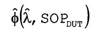
wavelength determination path 6 is set to a different state. The state of polarization SOPDUT in thelight path 7 remains constant during all these wavelength sweeps. For each setting of SOPWRU, a different dependency ofon λ and is obtained. In order to reduce or even eliminate the DUT-parameter measurement error error, the average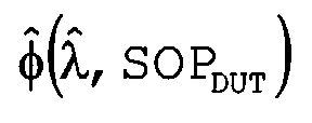 of the various functions
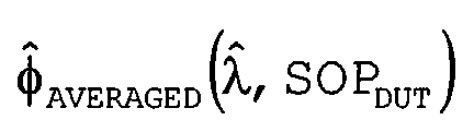 recorded for different SOPWRU is calculated. The measurement inaccuracy is considerably reduced by averaging the optical parameter and over different states of polarization SOPWRU.
- Fig. 4A and 4B show how this averaging procedure is performed. In Fig. 4A, λ and(kT, SOPWRU) is depicted as a function of time k.T for two different states of
polarization SOP WRU1 andSOP WRU2. During the first wavelength sweep, the state of polarization in thewavelength determination path 6 is set toSOP WRU1, and during the second wavelength sweep, it is set toSOP WRU2. It can be seen that there is a wavelength error superimposed on the measured wavelengths, which is periodical over the wavelength, and which depends on the state of polarization SOPWRU in the wavelength determination path. - For a suitable choice of SOPWRU1 and
SOP WRU2, the measured wavelengths λ and(kT, SOPWRU1) and λ and(kT, SOPWRU2) are out of phase. For example, at the instant oftime 3T, the wavelength measured for λ and(kT, SOPWRU1) at themeasurement point 18 is smaller than λtrue, which means that there is a negative wavelength error. At themeasurement point 19, the wavelength measured for λ and(kT, SOPWRU2) is larger than the true wavelength λtrue, and there is a positive wavelength error. - For each instant of time k·T, the optical parameter and is measured in the
sensor unit box 16, and a measurement value and(kT, SOPDUT) is obtained. Usually, one is interested in the wavelength dependence of and, and not in the time dependence of and, because the way and depends on the time depends on how the respective wavelength sweep is performed. There might be tunable laser sources that are capable of producing the same wavelength sweeps again and again, but usually, there is some variability, and the dependency of the wavelength on time is not strictly linear. Some wavelength sweeps might rise more quickly than others. For this reason, it is desirable to get rid of the time dependence of and(kT, SOPDUT) and to express and in terms of the wavelength. - For a certain instant of time, for example for the instant of
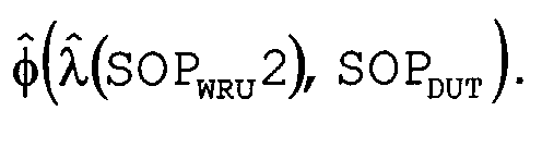
time 3T, the measured parameter value and(3T, SOPDUT) is related to the corresponding wavelength value measured at this instant of time, in our example to λ and(3T, SOPWRU). In Fig. 4B, the thus obtained dependencies of and on λ and are shown for two different states ofpolarization SOP WRU1 andSOP WRU2. When relating and to λ and at the point oftime 3T forSOP WRU1, themeasurement point 18 is obtained. When relating and to λ and at the same point oftime 3T forSOP WRU2, themeasurement point 19 is obtained. By relating each value of and to corresponding values of λ and for at least two different states ofpolarization SOP WRU1 andSOP WRU2, the curvesand are obtained. The oscillations that can still be seen in these curves of and as a function of λ and result from the polarization dependent wavelength error shown in Fig. 4A. This wavelength error is transformed in a corresponding DUT-parameter measurement error anderror.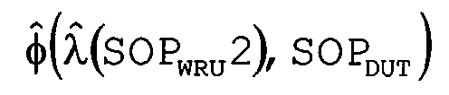
- In order to eliminate or at least reduce the DUT-parameter measurement error anderror, the
processing unit 14 calculates the arithmetic means ofand The averaged DUT-parameter
 is obtained, which gives a dependency of the averaged DUT-parameter andAVERAGED on λ and and SOPDUT. The averaging procedure is no longer performed with respect to time, but with respect to wavelength. For example, the measurement points 20 and 21 correspond to the same wavelength λ and. The averaged
point 22 is obtained by averaging the value and ofpoint 20 and ofpoint 21. The measurement points 20 and 21 have not been recorded at the same time, though.Measurement point 20 has been recorded at a time t > 3T, andmeasurement point 21 has been recorded at a time t < 3T. Therefore, the averaging procedure is no longer performed with respect to values of and that correspond to the same time t, but with respect to values of and that correspond to the same wavelength. The time dependency of the wavelength sweeps is no longer important for this kind of averaging procedure, and therefore, the requirements concerning the accuracy of the wavelength sweeps can be considerably reduced. - When the states of polarization SOPWRU1 and
SOP WRU2 are chosen in a suitable way,and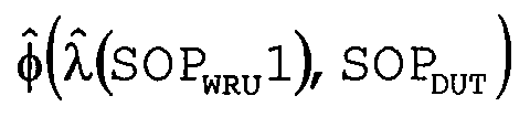 are sufficiently out of phase, and the periodical error anderror superimposed on
 is considerably reduced. In Fig. 4B, the averaged DUT-parameter
 is shown as a function of λ and.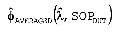
- In the following, a third embodiment of the invention will be described that is shown in Fig. 5. A
tunable laser source 23 emitsmonochromatic light 24 and performs wavelength sweeps, whereby the state of polarization (SOP) of saidmonochromatic light 24 is set by thepolarization controller 25. The set-up shown in Fig. 5 comprises only onesingle polarization controller 25, which sets the state of polarization both for thewavelength determination path 26 and for the opticalparameter determination path 27. This is the main difference between the third embodiment shown in Fig. 5 and the second embodiment shown in Fig. 3. While in the second embodiment of the invention, the states of polarization SOPWRU and SOPDUT can be set independently from each other, in the third embodiment, there is only one state of polarization SOP for both thewavelength determination path 26 and the opticalparameter determination path 27. For certain types of optical measurements, such as the determination of the Jones matrix and of the Differential Group Delay (DGD), this is sufficient. -
Light 28 with a well-defined state of polarization is forwarded to thewavelength reference unit 29, in order to determine, in regular time intervals, the wavelength. For this purpose, thewavelength reference unit 29 might comprise interferometric devices as described above. The measured wavelength λ and(kT, SOP), which depends on the state of polarization SOP, is forwarded to the processing unit 30. - The optical
parameter determination path 27 comprises asensor unit box 31 that contains a device under test (DUT) 32. Thesensor unit box 31 might for example determine the horizontal component Itx as well as the vertical component Ity of the light intensity transmitted through the device undertest 32. In this case, both thehorizontal component 33 and thevertical component 34 of the intensity are forwarded to the processing unit 30. - In the following, it will be described how the measurement set-up shown in Fig. 5 can be used for determining the Jones matrix as a function of wavelength for a device under test. The Jones matrixdescribes how the device under test transforms an incident light wave
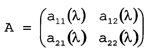 into a transmitted light wave
 :
:
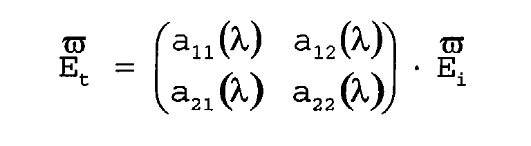
- The parameters a11(λ), a12(λ), a21(λ), a22(λ) are complex parameters that vary as a function of λ.
- Two wavelength scans are performed, with each wavelength scan comprising two wavelength sweeps, in order to determine the Jones matrix A. The first wavelength scan "Scan1" comprises a first wavelength sweep with a state of polarization SOP1, and a second wavelength sweep with a state of polarization SOP2, whereby the state of polarization SOP2 is orthogonal to SOP1. During each of said two wavelength sweeps, both the
horizontal component 33 and thevertical component 34 of the transmitted intensity are determined. From the data obtained during Scan1, the complex matrix elements a11(λ), a12(λ), a21(λ), a22(λ) of the Jones matrix J can be calculated as a function of wavelength λ. Next, a Jones Matrix Eigenvalue (JME) analysis is performed, and the two Eigenvalues EV1(λ, Scan1), EV2(λ, Scan1) of J'J-1, J' stands for the differentiation with respect to the wavelength, are obtained as a function of wavelength λ. - The second wavelength scan "Scan2" also comprises two wavelength sweeps.
- Compared to Scan1, the states of polarization are shifted by a parameter Δ. Therefore, during the first wavelength sweep of Scan2, the state of polarization is SOP1+Δ. During the second wavelength sweep of Scan2, the state of polarization is SOP2+Δ. Again, the data recorded during the two wavelength sweeps of Scan2 allows to determine all the complex matrix elements of the Jones matrix A as a function of λ. After performing a Jones Matrix Eigenvalue (JME) analysis for the data of Scan2, the two Eigenvalues EV1(λ, Scan2), EV2(λ, Scan2) are obtained.
- The Eigenvalues EV1, EV2 of J'J-1 can be used for calculating the Differential Group Delay (DGD), which is defined as the difference of the imaginary parts of said two Eigenvalues. For Scan1, the Differential Group Delay DGD(λ, Scan1) is equal to Im(EV1(λ, Scan1) - EV2(λ, Scan1)). Correspondingly, for Scan2, the Differential Group Delay DGD(λ, Scan2) is obtained as Im(EV1(λ, Scan2) - EV2(λ, Scan2)).
- In Fig. 6A, the Differential Group Delay DGD(λ, Scan1) determined from Scan1 is shown as a function of λ. Correspondingly, Fig. 6B depicts the Differential Group Delay DGD(λ, Scan2) determined from Scan2 as a function of λ. It can be seen that both for DGD(λ, Scan1) and for DGD(λ, Scan2), there is an oscillating error superimposed on the Differential Group Delay that depends on the states of polarization during the wavelength sweeps of Scan1 and Scan2. The oscillations are out of phase, and therefore, the error can be reduced by performing an averaging procedure. DGDAVERAGED(λ) is obtained as the arithmetic means of DGD(λ, Scan1) and DGD(λ, Scan2):
- In Fig. 6C, the averaged Differential Group Delay DGDAVERAGED(λ) is shown as a function of wavelength. A measurement set-up of the kind shown in Fig. 5 allows to considerably reduce polarization dependent error.
- Similarly, the Jones matrix can be used for calculating the polarization dependent insertion loss characteristics (average loss and polarization dependent loss, PDL) and the Group Delay (GD) characteristic of the DUT.
Claims (23)
- An apparatus comprising:a first polarization controller (3, 10, 25) adapted for setting the state of polarization of an incident light (2, 9, 24), or a part thereof, in order to generate a first polarized output (4, 12, 28) with at least two different states of polarization;a first determination unit (5, 13, 29) adapted for determining a first optical property for each of said at least two states of polarization of the first polarized output (4, 12, 28); anda processing unit (5, 14, 30) adapted for determining a mean value of the first optical property determined for said at least two states of polarization, or of a property derived therefrom.
- The apparatus of claim 1, further comprising:a second determination unit (16, 31) adapted for receiving a response signal of a device under test - DUT - (17, 32) in response to a signal derived from the incident light (9, 24), and for determining from the response signal a first DUT property, wherein the first DUT property represents an optical property of the DUT;wherein the processing unit (14, 30) is adapted for deriving an averaged DUT property from the first optical property and the first DUT property by determining a mean value of at least one of: the first optical property determined for said at least two states of polarization, or a property derived from the first optical property as well as from the first DUT property for each of said at least two states of polarization.
- The apparatus according to claim 1 or any one of the above claims, wherein said first optical property is the wavelength of the incident light (2, 9, 24).
- The apparatus according to claim 1 or any one of the above claims, wherein said first determination unit (5, 13, 29) comprises an interferometric device, preferably an interferometric device of the Michelson type or of the Mach-Zehnder type.
- The apparatus according to claim 1 or any one of the above claims, wherein said incident light (2, 9, 24) is generated by a tunable light source (1, 8, 23), preferably a tunable laser source, preferably adapted to perform a wavelength sweep by continuously increasing or decreasing the wavelength of said incident light over a range of wavelengths.
- The apparatus according to claim 1 or any one of the above claims, wherein a separate wavelength sweep is performed for each of said at least two states of polarization, whereby during a wavelength sweep, the state of polarization is kept substantially constant.
- The apparatus according to claim 1 or any one of the above claims, wherein during a wavelength sweep, the first optical property is repeatedly determined at discrete instants of time.
- The apparatus according to claim 2 or any one of the above claims, wherein the processing unit (14, 30) relates values of the first DUT property to corresponding values of the first optical property and determines the first DUT property as a function of the first optical property for said at least two states of polarization, before said averaged DUT property is derived.
- The apparatus according to claim 2 or any one of the above claims, wherein said processing unit (14, 30) determines the average of values of the first DUT property that correspond to the same value of said first optical property.
- The apparatus according to claim 2 or any one of the above claims, wherein during a wavelength sweep, both the first DUT property and the first optical property are repeatedly determined at discrete instants of time.
- The apparatus according to claim 2 or any one of the above claims, wherein said first polarized output (28) generated by the first polarization controller (25) is provided both to the first determination unit (29) and to the DUT (32), in order to obtain both the first optical property and the first DUT signal for said at least two states of polarization of the first polarized output (28).
- The apparatus according to claim 11, wherein said first DUT property is the Jones Matrix of the DUT, which is determined as a function of the wavelength.
- The apparatus according to claim 12, wherein from said Jones Matrix, at least one of a value of Insertion Loss, Polarization Dependent Loss, Group Delay, or Differential Group Delay of the DUT is obtained.
- The apparatus according to claim 2 or any one of the above claims, whereinthe first polarization controller (10) is adapted for setting the state of polarization of a first part of the incident light (9), in order to generate the first polarized output (12), which is provided to the first determination unit (13),the apparatus comprises a second polarization controller (11) adapted for setting the state of polarization of a second part of the incident light (9), whereby the state of polarization of the second polarized output (15) is set independently of the state of polarization of the first polarized output (12), and whereby the second polarized output (15) is provided to the DUT (17) in order to obtain the response signal of the DUT (17).
- A method for determining an optical property, comprising the following steps:setting the state of polarization of an incident light (2, 9, 24), or a part thereof, to at least two different states of polarization, in order to generate a first polarized output (4, 12, 28);determining a first optical property for each of said at least two states of polarization of the first polarized output (4, 12, 28); anddetermining a mean value of the first optical property determined for said at least two states of polarization, or of a property derived therefrom.
- The method according to claim 15, further comprising the following steps:receiving a response signal of a device under test -DUT- (17, 32) in response to a signal derived from the incident light (9, 24);determining from the response signal a first DUT property, wherein the first DUT property represents an optical property of the DUT; andderiving an averaged DUT property from the first DUT property and the first optical property for each of said at least two states of polarization by determining a mean value of at least one of: the first optical property determined for said at least two states of polarization, or a property derived from the first optical property as well as from the first DUT property for each of said at least two states of polarization.
- The method according to claim 15 or any of the above method claims, wherein said first optical property is the wavelength of the incident light (2, 9, 24).
- The method according to claim 15 or any of the above method claims, wherein wavelength sweeps are performed by continuously increasing or decreasing the wavelength of said incident light (2, 9, 24) over a range of wavelengths.
- The method according to claim 15 or any of the above method claims wherein separate wavelength sweeps are performed for each of said at least two states of polarization, whereby during a wavelength sweep, the state of polarization is kept substantially constant.
- The method according to claim 15 or any of the above method claims, wherein during a wavelength sweep, the first optical property is repeatedly determined at discrete instants of time.
- The method according to claim 15 or any of the above method claims, wherein values of the first DUT property are related to corresponding values of the first optical property, and the first DUT property is determined as a function of the first optical property for said at least two states of polarization, before the averaged DUT property is derived.
- The method according to claim 15 or any of the above method claims, wherein the average of values of the first DUT property that correspond to the same value of the first optical property is determined.
- The method according to claim 15 or any of the above method claims, wherein during a wavelength sweep, both the first DUT property and the first optical property are repeatedly determined at discrete instants of time.
Priority Applications (3)
| Application Number | Priority Date | Filing Date | Title |
|---|---|---|---|
| EP02018761A EP1329702B1 (en) | 2002-08-22 | 2002-08-22 | Polarization effect averaging |
| DE60203362T DE60203362T2 (en) | 2002-08-22 | 2002-08-22 | Averaging by polarization effects |
| US10/462,341 US7180599B2 (en) | 2002-08-22 | 2003-06-13 | Polarization effect averaging |
Applications Claiming Priority (1)
| Application Number | Priority Date | Filing Date | Title |
|---|---|---|---|
| EP02018761A EP1329702B1 (en) | 2002-08-22 | 2002-08-22 | Polarization effect averaging |
Publications (2)
| Publication Number | Publication Date |
|---|---|
| EP1329702A1 true EP1329702A1 (en) | 2003-07-23 |
| EP1329702B1 EP1329702B1 (en) | 2005-03-23 |
Family
ID=8185478
Family Applications (1)
| Application Number | Title | Priority Date | Filing Date |
|---|---|---|---|
| EP02018761A Expired - Lifetime EP1329702B1 (en) | 2002-08-22 | 2002-08-22 | Polarization effect averaging |
Country Status (3)
| Country | Link |
|---|---|
| US (1) | US7180599B2 (en) |
| EP (1) | EP1329702B1 (en) |
| DE (1) | DE60203362T2 (en) |
Cited By (1)
| Publication number | Priority date | Publication date | Assignee | Title |
|---|---|---|---|---|
| EP1628121A1 (en) * | 2004-08-18 | 2006-02-22 | Agilent Technologies Inc | Determination of polarization dependent properties |
Families Citing this family (3)
| Publication number | Priority date | Publication date | Assignee | Title |
|---|---|---|---|---|
| DE60203362T2 (en) * | 2002-08-22 | 2005-09-08 | Agilent Technologies, Inc. (n.d.Ges.d.Staates Delaware), Palo Alto | Averaging by polarization effects |
| US7426021B2 (en) * | 2004-11-29 | 2008-09-16 | Expo Electro- Optical Engineering Inc. | Interferometric optical analyzer and method for measuring the linear response of an optical component |
| DE102020116167A1 (en) * | 2020-06-18 | 2021-12-23 | Instrument Systems Optische Messtechnik Gmbh | Measuring system for measuring light sources |
Citations (4)
| Publication number | Priority date | Publication date | Assignee | Title |
|---|---|---|---|---|
| US3927945A (en) * | 1974-10-29 | 1975-12-23 | Harry Eugene Bates | Optical coherence and wavelength measurement |
| GB2350184A (en) * | 1999-05-19 | 2000-11-22 | Furukawa Electric Europ Ltd | Apparatus and method to measure wavelength |
| EP1191320A1 (en) * | 2001-06-07 | 2002-03-27 | Agilent Technologies, Inc. (a Delaware corporation) | Measurement of polarization dependent characteristic of optical components |
| US20020093644A1 (en) * | 1997-02-14 | 2002-07-18 | Jds Uniphase Corporation | Apparatus and method for generation of optical signals |
Family Cites Families (5)
| Publication number | Priority date | Publication date | Assignee | Title |
|---|---|---|---|---|
| EP1113250B1 (en) * | 2000-11-17 | 2003-02-05 | Agilent Technologies, Inc. (a Delaware corporation) | Method and apparatus for determining the polarisation mode dispersion of an optical device |
| US6943891B2 (en) * | 2002-03-15 | 2005-09-13 | Agilent Technologies, Inc. | Determining optical characteristics of optical devices under test |
| US7009691B2 (en) * | 2002-05-29 | 2006-03-07 | Agilent Technologies, Inc. | System and method for removing the relative phase uncertainty in device characterizations performed with a polarimeter |
| DE60203362T2 (en) * | 2002-08-22 | 2005-09-08 | Agilent Technologies, Inc. (n.d.Ges.d.Staates Delaware), Palo Alto | Averaging by polarization effects |
| US7426021B2 (en) * | 2004-11-29 | 2008-09-16 | Expo Electro- Optical Engineering Inc. | Interferometric optical analyzer and method for measuring the linear response of an optical component |
-
2002
- 2002-08-22 DE DE60203362T patent/DE60203362T2/en not_active Expired - Fee Related
- 2002-08-22 EP EP02018761A patent/EP1329702B1/en not_active Expired - Lifetime
-
2003
- 2003-06-13 US US10/462,341 patent/US7180599B2/en not_active Expired - Fee Related
Patent Citations (4)
| Publication number | Priority date | Publication date | Assignee | Title |
|---|---|---|---|---|
| US3927945A (en) * | 1974-10-29 | 1975-12-23 | Harry Eugene Bates | Optical coherence and wavelength measurement |
| US20020093644A1 (en) * | 1997-02-14 | 2002-07-18 | Jds Uniphase Corporation | Apparatus and method for generation of optical signals |
| GB2350184A (en) * | 1999-05-19 | 2000-11-22 | Furukawa Electric Europ Ltd | Apparatus and method to measure wavelength |
| EP1191320A1 (en) * | 2001-06-07 | 2002-03-27 | Agilent Technologies, Inc. (a Delaware corporation) | Measurement of polarization dependent characteristic of optical components |
Cited By (2)
| Publication number | Priority date | Publication date | Assignee | Title |
|---|---|---|---|---|
| EP1628121A1 (en) * | 2004-08-18 | 2006-02-22 | Agilent Technologies Inc | Determination of polarization dependent properties |
| US7352450B2 (en) | 2004-08-18 | 2008-04-01 | Thomas Jensen | Determination of polarization dependent properties |
Also Published As
| Publication number | Publication date |
|---|---|
| DE60203362D1 (en) | 2005-04-28 |
| US20040036889A1 (en) | 2004-02-26 |
| EP1329702B1 (en) | 2005-03-23 |
| US7180599B2 (en) | 2007-02-20 |
| DE60203362T2 (en) | 2005-09-08 |
Similar Documents
| Publication | Publication Date | Title |
|---|---|---|
| EP3956689B1 (en) | Time-of-flight measurements using linear inverse function | |
| EP1420238B1 (en) | Determining an optical property by using superimposed delayed signals | |
| JP4667728B2 (en) | Sweep wavelength meter and wavelength calibration method | |
| JP4722110B2 (en) | Wavelength calibration apparatus and method for swept laser | |
| US7009691B2 (en) | System and method for removing the relative phase uncertainty in device characterizations performed with a polarimeter | |
| EP1172637A1 (en) | Device for calibrating a wavelength measuring unit | |
| US6486961B1 (en) | System and method for measuring group delay based on zero-crossings | |
| US10677726B2 (en) | Tunable diode laser absorption spectroscopy with corrected laser ramping nonlinearities | |
| EP1424546A2 (en) | Optical analyzer and method for reducing relative intensity noise in interferometric optical measurements | |
| JP6293762B2 (en) | Position monitoring system with reduced noise | |
| US5654793A (en) | Method and apparatus for high resolution measurement of very low levels of polarization mode dispersion (PMD) in single mode optical fibers and for calibration of PMD measuring instruments | |
| JP2021522517A (en) | Absorber | |
| Moore | Advances in swept-wavelength interferometry for precision measurements | |
| CN116009011B (en) | Radar detection method and related device | |
| EP1329702B1 (en) | Polarization effect averaging | |
| AU6022896A (en) | Measurement of polarization mode dispersion | |
| Oberson et al. | Interferometric polarization mode dispersion measurements with femtosecond sensitivity | |
| Burtscher et al. | Observing faint targets with MIDI at the VLTI: the MIDI AGN large programme experience | |
| Neal et al. | Use of beam parameters in optical component testing | |
| WO2004005877A1 (en) | Method, system and device for measuring the polarisation mode dispersion of an optical fibre | |
| EP1353162A1 (en) | Determination of a device signal response characteristic using multiple varied signals | |
| Vaganov | Information approach to estimation of an optical spectral device efficiency | |
| Salzenstein et al. | Uncertainty analysis in optoelectronic and photonic metrology: phase noise, frequency stability, and Brillouin scattering measurements | |
| US20030133122A1 (en) | Time difference synchronisation for determination of a property of an optical device | |
| Cyr et al. | PMD measurements in multipath components: the single-waveplate example |
Legal Events
| Date | Code | Title | Description |
|---|---|---|---|
| PUAI | Public reference made under article 153(3) epc to a published international application that has entered the european phase |
Free format text: ORIGINAL CODE: 0009012 |
|
| 17P | Request for examination filed |
Effective date: 20030522 |
|
| AK | Designated contracting states |
Designated state(s): AT BE BG CH CY CZ DE DK EE ES FI FR GB GR IE IT LI LU MC NL PT SE SK TR |
|
| AX | Request for extension of the european patent |
Extension state: AL LT LV MK RO SI |
|
| 17Q | First examination report despatched |
Effective date: 20030908 |
|
| AKX | Designation fees paid |
Designated state(s): DE FR GB |
|
| GRAP | Despatch of communication of intention to grant a patent |
Free format text: ORIGINAL CODE: EPIDOSNIGR1 |
|
| GRAS | Grant fee paid |
Free format text: ORIGINAL CODE: EPIDOSNIGR3 |
|
| GRAA | (expected) grant |
Free format text: ORIGINAL CODE: 0009210 |
|
| AK | Designated contracting states |
Kind code of ref document: B1 Designated state(s): DE FR GB |
|
| REG | Reference to a national code |
Ref country code: GB Ref legal event code: FG4D |
|
| REG | Reference to a national code |
Ref country code: IE Ref legal event code: FG4D |
|
| REF | Corresponds to: |
Ref document number: 60203362 Country of ref document: DE Date of ref document: 20050428 Kind code of ref document: P |
|
| PLBE | No opposition filed within time limit |
Free format text: ORIGINAL CODE: 0009261 |
|
| STAA | Information on the status of an ep patent application or granted ep patent |
Free format text: STATUS: NO OPPOSITION FILED WITHIN TIME LIMIT |
|
| ET | Fr: translation filed | ||
| 26N | No opposition filed |
Effective date: 20051227 |
|
| PGFP | Annual fee paid to national office [announced via postgrant information from national office to epo] |
Ref country code: GB Payment date: 20060825 Year of fee payment: 5 |
|
| PGFP | Annual fee paid to national office [announced via postgrant information from national office to epo] |
Ref country code: FR Payment date: 20060831 Year of fee payment: 5 |
|
| PGFP | Annual fee paid to national office [announced via postgrant information from national office to epo] |
Ref country code: DE Payment date: 20071001 Year of fee payment: 6 |
|
| GBPC | Gb: european patent ceased through non-payment of renewal fee |
Effective date: 20070822 |
|
| REG | Reference to a national code |
Ref country code: FR Ref legal event code: ST Effective date: 20080430 |
|
| PG25 | Lapsed in a contracting state [announced via postgrant information from national office to epo] |
Ref country code: FR Free format text: LAPSE BECAUSE OF NON-PAYMENT OF DUE FEES Effective date: 20070831 |
|
| PG25 | Lapsed in a contracting state [announced via postgrant information from national office to epo] |
Ref country code: GB Free format text: LAPSE BECAUSE OF NON-PAYMENT OF DUE FEES Effective date: 20070822 |
|
| PG25 | Lapsed in a contracting state [announced via postgrant information from national office to epo] |
Ref country code: DE Free format text: LAPSE BECAUSE OF NON-PAYMENT OF DUE FEES Effective date: 20090303 |