EP1329661A2 - Cleanable pipe for discharge system - Google Patents
Cleanable pipe for discharge system Download PDFInfo
- Publication number
- EP1329661A2 EP1329661A2 EP03001019A EP03001019A EP1329661A2 EP 1329661 A2 EP1329661 A2 EP 1329661A2 EP 03001019 A EP03001019 A EP 03001019A EP 03001019 A EP03001019 A EP 03001019A EP 1329661 A2 EP1329661 A2 EP 1329661A2
- Authority
- EP
- European Patent Office
- Prior art keywords
- cleaning tube
- cleanout
- cleaning
- tube
- cleanout door
- Prior art date
- Legal status (The legal status is an assumption and is not a legal conclusion. Google has not performed a legal analysis and makes no representation as to the accuracy of the status listed.)
- Granted
Links
- 238000004140 cleaning Methods 0.000 claims abstract description 83
- 238000012856 packing Methods 0.000 claims abstract description 13
- 229910001220 stainless steel Inorganic materials 0.000 claims abstract description 3
- 239000010935 stainless steel Substances 0.000 claims abstract description 3
- 230000008021 deposition Effects 0.000 abstract 1
- XLYOFNOQVPJJNP-UHFFFAOYSA-N water Substances O XLYOFNOQVPJJNP-UHFFFAOYSA-N 0.000 description 4
- 238000000034 method Methods 0.000 description 2
- 229910001018 Cast iron Inorganic materials 0.000 description 1
- 229910000831 Steel Inorganic materials 0.000 description 1
- 238000000151 deposition Methods 0.000 description 1
- 238000009499 grossing Methods 0.000 description 1
- 239000000463 material Substances 0.000 description 1
- 238000007789 sealing Methods 0.000 description 1
- 239000007787 solid Substances 0.000 description 1
- 239000010959 steel Substances 0.000 description 1
Images

Classifications
-
- F—MECHANICAL ENGINEERING; LIGHTING; HEATING; WEAPONS; BLASTING
- F16—ENGINEERING ELEMENTS AND UNITS; GENERAL MEASURES FOR PRODUCING AND MAINTAINING EFFECTIVE FUNCTIONING OF MACHINES OR INSTALLATIONS; THERMAL INSULATION IN GENERAL
- F16L—PIPES; JOINTS OR FITTINGS FOR PIPES; SUPPORTS FOR PIPES, CABLES OR PROTECTIVE TUBING; MEANS FOR THERMAL INSULATION IN GENERAL
- F16L45/00—Pipe units with cleaning aperture and closure therefor
-
- E—FIXED CONSTRUCTIONS
- E04—BUILDING
- E04D—ROOF COVERINGS; SKY-LIGHTS; GUTTERS; ROOF-WORKING TOOLS
- E04D13/00—Special arrangements or devices in connection with roof coverings; Protection against birds; Roof drainage ; Sky-lights
- E04D13/04—Roof drainage; Drainage fittings in flat roofs, balconies or the like
- E04D13/08—Down pipes; Special clamping means therefor
-
- E—FIXED CONSTRUCTIONS
- E04—BUILDING
- E04D—ROOF COVERINGS; SKY-LIGHTS; GUTTERS; ROOF-WORKING TOOLS
- E04D13/00—Special arrangements or devices in connection with roof coverings; Protection against birds; Roof drainage ; Sky-lights
- E04D13/04—Roof drainage; Drainage fittings in flat roofs, balconies or the like
- E04D13/08—Down pipes; Special clamping means therefor
- E04D2013/0866—Access opening for cleaning; Devices for avoiding cumulation of debris
Definitions
- the present invention concerns a cleaning tube of the type adapted for mounting in pipe systems and preferably in drainage systems made of stainless steel, where the cleaning tube is provided with a cleanout door, which by opening provides access to the interior of the tube through a cleanout opening, the cleaning tube being adapted for mounting in pipe sections where the orientation of the tube between vertical and horizontal planes is without significance for the function of the cleaning tube, and where the cleaning tube is made with a cleanout opening having a dimension in transverse and/or longitudinal direction substantially corresponding to the internal diameter of the cleaning tube.
- a cleaning tube may be inserted as a module in a pipe system consisting of a number of pipe elements with each their spigot end and with each their socket end.
- the cleaning tube may be designed as a straight tube piece which is inserted in straight pipe sections or, alternatively, in a pipe bend with a given angle.
- Cleaning tubes may e.g. be used for pipe systems for drain water, thereby achieving the possibility of removing deposited elements or possibly alien bodies.
- the cleaning tube is made as a straight tube member at the side of which there is a projecting pipe stub which is closed with a door.
- the door is usually closed with an internal bayonet joint or with an external screw cap.
- the tube is made of cast iron, there are often two or more threaded pins projecting from the pipe stub to which a door may be fastened.
- These types may in some cases be made with an insert which is either attached to the door or separately in the pipe stub, where insert has the purpose of filling the recess appearing where the pipe stub is mounted. By smoothing out this recess, a more unimpeded flow is attained in the tube.
- cleaning tubes of galvanised steel where the cleanout door is normally secured by a clamp around the protruding end of the pipe stub.
- the cleaning tube according to the invention is peculiar in that it includes means ensuring unhindered flow through the cleaning tube, and which includes a collar part on the cleaning tube and an elastic sheet packing mounted on the cleanout door, and which by closed cleanout opening abuts on the collar part on the cleaning tube, whereby the sheet packing is compressed at contact with the collar part so that inside the cleaning tube there are no projections/recesses which are larger than at the joint of two smooth pipes.
- the cleaning tube is designed for an internal overpressure preferably in the order of magnitude 3 bars.
- a cleaning tube With a cleaning tube according to the invention, optimal efficiency in achieved during operation since by e.g. cleaning, access to the interior of the pipe system may easily be provided, and since no kind of depositing occurs in connection with the cleanout door during common operation.
- This property is achieved by ensuring a smooth and undisturbed passage through the pipe system, furthermore implying a markedly better self-cleaning of the pipe system and also ensuring more time between service intervals such as cleaning.
- the cleanout opening may alternatively have other shapes than circular.
- a cleaning tube where the opening has greater extension in longitudinal direction of the cleaning tube than in transverse direction can easily be made, so that the cleanout opening has elongated shape.
- the cleaning tube is made with unhindered flow through the tube, as the said elastic sheet packing by closed cleanout opening abuts on the collar part on the cleaning tube.
- the sheet packing is compressed by contact with the collar part so that internally of the cleaning tube there are no projections/recesses which are larger than at the joint of two smooth pipes.
- the sheet packing will, when the cleanout door is closed and tightened, be compressed at the location of the collar part, but at the area constituting the cleanout opening itself in the cleaning tube, the sheet packing will, due to its elasticity, fairly well fill out the entire recess naturally appearing between cleaning tube and cleanout door.
- This filling is of particularly great importance as hereby is ensure an optimal and free passage of e.g. drain water.
- drain water e.g.
- a broader application area may be achieved as the system is developed for pressure up to 3 bars. This may occur by suitable dimensioning and designing the sheet packing and the collar part as well as closing means.
- the cleaning tube according to the invention is peculiar in that the cleanout door is provided pivoting via a hinge and with a closing means, and that the cleanout door is fastened with fastening means, preferably with a screw, which is adapted for fastening in a counterpart adapted therefor.
- the cleaning tube may be designed with the closing means of the cleanout door, the counterpart of the cleaning tube and the fastening means being fitted so that there are no loose members, like screws or similar, when the cleanout door is opened.
- the closing means may have other common embodiments.
- the cleaning tube is designed so that the fastening means of the cleanout door may be operated without use of tools.
- This variant is particularly applicable in several different environments, inter alia if it is important to open rapidly, or if the cleaning tube is disposed in an area where tools are not or are not to be present readily.
- a cleaning tube 2 isometrically from the hinge side and with a cleanout door 4 closed.
- the upwardly directed end of the cleaning tube 2 is made with a socket end 10, and at the other end the tube is made with a spigot 8.
- the spigot end 8 and the socket end 10 are made exactly as on common drain pipes.
- the closed cleanout door 4 which is fastened to the cleaning tube 2 with a hinge 16 about which the cleanout door 4 may be turned away in order thereby to ensure optimal access to the interior of the cleaning tube 2.
- an elastic sheet packing 12 made of a material which can stand/is approved for the environment concerned.
- the elastic sheet packing 12 may be seen faintly between the cleanout door 4 and the cleaning tube 2.
- Fig. 2 shows the same cleaning tube 2 as Fig. 1, but here it is seen with the cleanout door 4 open.
- the cleanout door 4 is here shown only partly open, and it is to be noted that the cleanout door 4 may be opened significantly more, whereby is ensured optimal access to the interior of the pipe.
- the cleaning tube 2 around the cleanout opening has a collar part 14 which, together with the elastic sheet packing 12, provide optimal sealing between the cleaning tube 2 and the cleanout door 4.
- Fig. 3 shows the cleaning tube 2 with open cleanout door 4 as seen from the side and a detail showing the collar part 14 on the cleaning tube 2.
- FIG. 4 the cleaning tube 2 is shown from the other side, where a closing means 18 on the cleanout door 4 is clearly seen.
- the closing means 18 interacts with fastening means 22, preferably a screw 22, which is adapted for fastening in a counterpart 20 adapted therefor on the cleaning tube.
Landscapes
- Engineering & Computer Science (AREA)
- General Engineering & Computer Science (AREA)
- Architecture (AREA)
- Civil Engineering (AREA)
- Structural Engineering (AREA)
- Mechanical Engineering (AREA)
- Sink And Installation For Waste Water (AREA)
- Cleaning In General (AREA)
- Rigid Pipes And Flexible Pipes (AREA)
- External Artificial Organs (AREA)
- Quick-Acting Or Multi-Walled Pipe Joints (AREA)
- Cyclones (AREA)
- Electrical Discharge Machining, Electrochemical Machining, And Combined Machining (AREA)
- Centrifugal Separators (AREA)
Abstract
Description
- The present invention concerns a cleaning tube of the type adapted for mounting in pipe systems and preferably in drainage systems made of stainless steel, where the cleaning tube is provided with a cleanout door, which by opening provides access to the interior of the tube through a cleanout opening, the cleaning tube being adapted for mounting in pipe sections where the orientation of the tube between vertical and horizontal planes is without significance for the function of the cleaning tube, and where the cleaning tube is made with a cleanout opening having a dimension in transverse and/or longitudinal direction substantially corresponding to the internal diameter of the cleaning tube.
- Cleaning tubes with an opening closed with a cleanout door are commonly known and have been regularly used for a long time. A cleaning tube may be inserted as a module in a pipe system consisting of a number of pipe elements with each their spigot end and with each their socket end. The cleaning tube may be designed as a straight tube piece which is inserted in straight pipe sections or, alternatively, in a pipe bend with a given angle. Cleaning tubes may e.g. be used for pipe systems for drain water, thereby achieving the possibility of removing deposited elements or possibly alien bodies.
- Most often, the cleaning tube is made as a straight tube member at the side of which there is a projecting pipe stub which is closed with a door. If the cleaning tube is made in plastic, the door is usually closed with an internal bayonet joint or with an external screw cap. On the other hand, if the tube is made of cast iron, there are often two or more threaded pins projecting from the pipe stub to which a door may be fastened. These types may in some cases be made with an insert which is either attached to the door or separately in the pipe stub, where insert has the purpose of filling the recess appearing where the pipe stub is mounted. By smoothing out this recess, a more unimpeded flow is attained in the tube.
- Among other types may be mentioned cleaning tubes of galvanised steel, where the cleanout door is normally secured by a clamp around the protruding end of the pipe stub.
- In the prior art cleaning tube, there is often a design of the cleanout opening and the door so that there is no easy access through the cleanout opening.
- From WO 89/05418 there is known a cleaning tube of the type mentioned in the introduction, where easy access is provided through the cleanout opening.
- It is the purpose of the invention to indicate a cleanout tube to a pipe system where there is achieved an optimal and free and unhindered through-flow, e.g. of drain water, and which pipe system is preferably suited for applications where the pressure is up to 3 bars.
- The cleaning tube according to the invention is peculiar in that it includes means ensuring unhindered flow through the cleaning tube, and which includes a collar part on the cleaning tube and an elastic sheet packing mounted on the cleanout door, and which by closed cleanout opening abuts on the collar part on the cleaning tube, whereby the sheet packing is compressed at contact with the collar part so that inside the cleaning tube there are no projections/recesses which are larger than at the joint of two smooth pipes.
- According to a special embodiment of the invention, the cleaning tube is designed for an internal overpressure preferably in the order of magnitude 3 bars.
- With a cleaning tube according to the invention, optimal efficiency in achieved during operation since by e.g. cleaning, access to the interior of the pipe system may easily be provided, and since no kind of depositing occurs in connection with the cleanout door during common operation. This property is achieved by ensuring a smooth and undisturbed passage through the pipe system, furthermore implying a markedly better self-cleaning of the pipe system and also ensuring more time between service intervals such as cleaning.
- The cleanout opening may alternatively have other shapes than circular. For example, a cleaning tube where the opening has greater extension in longitudinal direction of the cleaning tube than in transverse direction can easily be made, so that the cleanout opening has elongated shape. Hereby is achieved still better access to the interior of the tube. By such variants, it maybe suitable to have plural hinges and/or closing means at each cleanout door.
- The cleaning tube is made with unhindered flow through the tube, as the said elastic sheet packing by closed cleanout opening abuts on the collar part on the cleaning tube. Hereby, the sheet packing is compressed by contact with the collar part so that internally of the cleaning tube there are no projections/recesses which are larger than at the joint of two smooth pipes.
- The sheet packing will, when the cleanout door is closed and tightened, be compressed at the location of the collar part, but at the area constituting the cleanout opening itself in the cleaning tube, the sheet packing will, due to its elasticity, fairly well fill out the entire recess naturally appearing between cleaning tube and cleanout door. This filling is of particularly great importance as hereby is ensure an optimal and free passage of e.g. drain water. Thus there are no edges onto which solids occurring in the drain water may be attached, thereby clogging the pipe system. With this smooth interior there is also, as mentioned, achieved a self-cleaning effect.
- Furthermore, a broader application area may be achieved as the system is developed for pressure up to 3 bars. This may occur by suitable dimensioning and designing the sheet packing and the collar part as well as closing means.
- According to a special embodiment, the cleaning tube according to the invention is peculiar in that the cleanout door is provided pivoting via a hinge and with a closing means, and that the cleanout door is fastened with fastening means, preferably with a screw, which is adapted for fastening in a counterpart adapted therefor. The cleaning tube may be designed with the closing means of the cleanout door, the counterpart of the cleaning tube and the fastening means being fitted so that there are no loose members, like screws or similar, when the cleanout door is opened. Alternatively, the closing means may have other common embodiments.
- By not having to worry about diverse small parts, it is associated with greater safety in connection with opening the cleanout door simultaneously with it being convenient not having to take care of screws and nuts, of course.
- In an alternative embodiment, the cleaning tube is designed so that the fastening means of the cleanout door may be operated without use of tools.
- This variant is particularly applicable in several different environments, inter alia if it is important to open rapidly, or if the cleaning tube is disposed in an area where tools are not or are not to be present readily.
- In the following, the invention is described with reference to the drawing, which, without being limiting, shows a preferred embodiment for a cleaning tube according to the invention, and where:
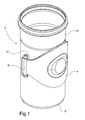
- Fig. 1
- shows a cleaning tube according to the invention, viewed isometrically from the hinge side and with a closed cleanout door,
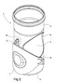
- Fig. 2
- shows the cleaning tube as in Fig. 1, but here with open cleanout door,
- Fig. 3
- shows the cleaning tube viewed from the other side, and
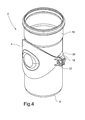
- Fig. 4
- shows the collar part of the cleaning tube in detail.
- In Fig. 1 is seen a
cleaning tube 2 isometrically from the hinge side and with acleanout door 4 closed. The upwardly directed end of thecleaning tube 2 is made with asocket end 10, and at the other end the tube is made with aspigot 8. Thespigot end 8 and thesocket end 10 are made exactly as on common drain pipes. At the front is seen the closedcleanout door 4 which is fastened to thecleaning tube 2 with ahinge 16 about which thecleanout door 4 may be turned away in order thereby to ensure optimal access to the interior of thecleaning tube 2. - On the
cleanout door 4 there is fitted anelastic sheet packing 12 made of a material which can stand/is approved for the environment concerned. In Fig. 1, theelastic sheet packing 12 may be seen faintly between thecleanout door 4 and thecleaning tube 2. - Fig. 2 shows the
same cleaning tube 2 as Fig. 1, but here it is seen with thecleanout door 4 open. Thecleanout door 4 is here shown only partly open, and it is to be noted that thecleanout door 4 may be opened significantly more, whereby is ensured optimal access to the interior of the pipe. In Fig. 2 is also seen that thecleaning tube 2 around the cleanout opening has acollar part 14 which, together with theelastic sheet packing 12, provide optimal sealing between thecleaning tube 2 and thecleanout door 4. - Fig. 3 shows the
cleaning tube 2 withopen cleanout door 4 as seen from the side and a detail showing thecollar part 14 on thecleaning tube 2. - In Fig. 4, the
cleaning tube 2 is shown from the other side, where a closing means 18 on thecleanout door 4 is clearly seen. The closing means 18 interacts with fastening means 22, preferably ascrew 22, which is adapted for fastening in acounterpart 20 adapted therefor on the cleaning tube. - The example shown here is a commonly known method and may without any problems be substituted by other known methods for joining parts or closing cleanout doors.
Claims (5)
- A cleaning tube of the type adapted for mounting in pipe systems and preferably in drainage systems made of stainless steel, where the cleaning tube is provided with a cleanout door (4), which by opening provides access to the interior of the tube through a cleanout opening (6), the cleaning tube (2) being adapted for mounting in pipe sections where the orientation of the tube between vertical and horizontal planes is without significance for the function of the cleaning tube, and where the cleaning tube (2) is made with a cleanout opening (6) having a dimension in transverse and/or longitudinal direction substantially corresponding to the internal diameter of the cleaning tube, characterised in that it includes means (12,14) ensuring unhindered flow through the cleaning tube (2), and which includes a collar part (14) on the cleaning tube (2) and an elastic sheet packing (12) mounted on the cleanout door (4), and which by closed cleanout opening (6) abuts on the collar part (14) on the cleaning tube (2), whereby the sheet packing (12) is compressed at contact with the collar part (14) so that inside the cleaning tube (2) there are no projections/recesses which are larger than at the joint of two smooth pipes.
- A cleaning tube according to claim 1, characterised in that the cleaning tube (2) is designed for an internal overpressure, preferably in the order of magnitude 3 bars.
- A cleaning tube according to claim 1 or 2, characterised in that the cleanout door (4) is provided with a hinge (16) and with a closing means (18), and that the cleanout door (4) is fastened with fastening means (22), preferably with a screw (22), which is adapted for fastening in a counterpart (20) adapted therefore on the cleaning tube.
- A cleaning tube according to any preceding claim, characterised in that closing means (18) of the cleanout door, the counter part (20) of the cleaning tube and the fastening means (22) are all mounted so that there are no loose parts such as screws or the like, when the cleanout door (4) is opened.
- A cleaning tube according to any preceding claim, characterised in that the closing means of the cleanout door and the fastening means (18, 20, 22) may be operated without using tools.
Applications Claiming Priority (2)
| Application Number | Priority Date | Filing Date | Title |
|---|---|---|---|
| DK200200085 | 2002-01-18 | ||
| DK200200085A DK174924B1 (en) | 2002-01-18 | 2002-01-18 | Purifier for mounting in piping system, preferably drainage system |
Publications (3)
| Publication Number | Publication Date |
|---|---|
| EP1329661A2 true EP1329661A2 (en) | 2003-07-23 |
| EP1329661A3 EP1329661A3 (en) | 2003-10-22 |
| EP1329661B1 EP1329661B1 (en) | 2006-11-15 |
Family
ID=8161024
Family Applications (1)
| Application Number | Title | Priority Date | Filing Date |
|---|---|---|---|
| EP03001019A Expired - Lifetime EP1329661B1 (en) | 2002-01-18 | 2003-01-17 | Cleanable pipe for discharge system |
Country Status (4)
| Country | Link |
|---|---|
| EP (1) | EP1329661B1 (en) |
| AT (1) | ATE345464T1 (en) |
| DE (1) | DE60309607T2 (en) |
| DK (2) | DK174924B1 (en) |
Cited By (4)
| Publication number | Priority date | Publication date | Assignee | Title |
|---|---|---|---|---|
| RU2479783C2 (en) * | 2011-08-09 | 2013-04-20 | Вячеслав Петрович Рябинин | Telescopic manhole |
| WO2015008038A1 (en) * | 2013-07-16 | 2015-01-22 | Specialist Ventilation Services | A duct member and closure assembly for a duct member |
| EP3214353A1 (en) * | 2016-03-02 | 2017-09-06 | Dieter Bächle | Tube unit for the air supply as well as for the discharge of exaust fumes of compustion equipments |
| CN107575695A (en) * | 2017-09-26 | 2018-01-12 | 刘海强 | Compound pipeline complex pipeline |
Families Citing this family (5)
| Publication number | Priority date | Publication date | Assignee | Title |
|---|---|---|---|---|
| RU2321793C1 (en) * | 2006-06-21 | 2008-04-10 | Вячеслав Петрович Рябинин | Service hatch for pipeline |
| RU2338953C2 (en) * | 2007-03-07 | 2008-11-20 | Вячеслав Петрович Рябинин | Pipeline shut-off device |
| RU2349828C2 (en) * | 2007-05-28 | 2009-03-20 | Вячеслав Петрович Рябинин | Device to block pipeline |
| RU2424462C2 (en) * | 2009-12-15 | 2011-07-20 | Вячеслав Петрович Рябинин | Pipeline latch-manhole |
| EP4527189A1 (en) | 2023-09-21 | 2025-03-26 | Husqvarna AB | An irrigation system |
Citations (1)
| Publication number | Priority date | Publication date | Assignee | Title |
|---|---|---|---|---|
| WO1989005418A1 (en) | 1987-12-07 | 1989-06-15 | Vilho Hinkkanen | A form part for a ventilation ductwork system |
Family Cites Families (2)
| Publication number | Priority date | Publication date | Assignee | Title |
|---|---|---|---|---|
| US3624794A (en) * | 1968-12-17 | 1971-11-30 | Irl Daffin Associates | Inspection means for concrete-handling system |
| US3724505A (en) * | 1971-05-11 | 1973-04-03 | G Jahn | Pipe or conduit clean out trap assembly |
-
2002
- 2002-01-18 DK DK200200085A patent/DK174924B1/en not_active IP Right Cessation
-
2003
- 2003-01-17 EP EP03001019A patent/EP1329661B1/en not_active Expired - Lifetime
- 2003-01-17 DK DK03001019T patent/DK1329661T3/en active
- 2003-01-17 AT AT03001019T patent/ATE345464T1/en not_active IP Right Cessation
- 2003-01-17 DE DE60309607T patent/DE60309607T2/en not_active Expired - Lifetime
Patent Citations (1)
| Publication number | Priority date | Publication date | Assignee | Title |
|---|---|---|---|---|
| WO1989005418A1 (en) | 1987-12-07 | 1989-06-15 | Vilho Hinkkanen | A form part for a ventilation ductwork system |
Cited By (5)
| Publication number | Priority date | Publication date | Assignee | Title |
|---|---|---|---|---|
| RU2479783C2 (en) * | 2011-08-09 | 2013-04-20 | Вячеслав Петрович Рябинин | Telescopic manhole |
| WO2015008038A1 (en) * | 2013-07-16 | 2015-01-22 | Specialist Ventilation Services | A duct member and closure assembly for a duct member |
| GB2516246B (en) * | 2013-07-16 | 2019-05-29 | Specialist Ventilation Services Ltd | A duct member |
| EP3214353A1 (en) * | 2016-03-02 | 2017-09-06 | Dieter Bächle | Tube unit for the air supply as well as for the discharge of exaust fumes of compustion equipments |
| CN107575695A (en) * | 2017-09-26 | 2018-01-12 | 刘海强 | Compound pipeline complex pipeline |
Also Published As
| Publication number | Publication date |
|---|---|
| ATE345464T1 (en) | 2006-12-15 |
| EP1329661A3 (en) | 2003-10-22 |
| EP1329661B1 (en) | 2006-11-15 |
| DK200200085A (en) | 2003-07-19 |
| DE60309607D1 (en) | 2006-12-28 |
| DK174924B1 (en) | 2004-02-23 |
| DK1329661T3 (en) | 2007-04-02 |
| DE60309607T2 (en) | 2007-10-11 |
Similar Documents
| Publication | Publication Date | Title |
|---|---|---|
| EP1329661B1 (en) | Cleanable pipe for discharge system | |
| US8869823B2 (en) | Non-return valve | |
| US8033486B2 (en) | Waste line connector assembly | |
| US20150275490A1 (en) | Plumbing waste arm with clean out | |
| US10364558B2 (en) | Bottle trap | |
| US20050178438A1 (en) | Flexible and extendable plumbing trap device | |
| US7350824B2 (en) | Drain fitting | |
| US8444184B2 (en) | Conduit structure for a hot water tap, as well as such tap | |
| US20050274415A1 (en) | Multiple valve drain and pipe-cleaning device | |
| CN211624539U (en) | Prevent blockking up return bend convenient to it is clean | |
| KR101345712B1 (en) | Blind board apparatus of blocking sewage smell | |
| FI3358093T3 (en) | Overflow or drain assembly and method for mounting an overflow or drain assembly on a tub | |
| JP2007100410A (en) | Joint for inner sub-pipe | |
| AU2022200053A1 (en) | Strainer | |
| KR200188214Y1 (en) | Trap | |
| JP4630996B2 (en) | Drainage equipment | |
| EP0329647A1 (en) | A pipe component containing a cleaning hatch | |
| KR100961750B1 (en) | Backflow prevention connecting valve | |
| CN222044359U (en) | Under counter basin drainage | |
| JP2023141741A (en) | Drainage equipment and drainage equipment construction method | |
| EP3880994B1 (en) | Valve unit | |
| KR102547993B1 (en) | Inspection port and piping connection structure | |
| KR200432272Y1 (en) | Drainage pipe | |
| JP4558605B2 (en) | Inner / sub pipe fittings | |
| KR930004992Y1 (en) | Flexible joint device for sprinkler piping |
Legal Events
| Date | Code | Title | Description |
|---|---|---|---|
| PUAI | Public reference made under article 153(3) epc to a published international application that has entered the european phase |
Free format text: ORIGINAL CODE: 0009012 |
|
| AK | Designated contracting states |
Designated state(s): AT BE BG CH CY CZ DE DK EE ES FI FR GB GR HU IE IT LI LU MC NL PT SE SI SK TR |
|
| AX | Request for extension of the european patent |
Extension state: AL LT LV MK RO |
|
| PUAL | Search report despatched |
Free format text: ORIGINAL CODE: 0009013 |
|
| AK | Designated contracting states |
Kind code of ref document: A3 Designated state(s): AT BE BG CH CY CZ DE DK EE ES FI FR GB GR HU IE IT LI LU MC NL PT SE SI SK TR |
|
| AX | Request for extension of the european patent |
Extension state: AL LT LV MK RO |
|
| 17P | Request for examination filed |
Effective date: 20040410 |
|
| AKX | Designation fees paid |
Designated state(s): AT BE BG CH CY CZ DE DK EE ES FI FR GB GR HU IE IT LI LU MC NL PT SE SI SK TR |
|
| 17Q | First examination report despatched |
Effective date: 20040803 |
|
| GRAP | Despatch of communication of intention to grant a patent |
Free format text: ORIGINAL CODE: EPIDOSNIGR1 |
|
| GRAS | Grant fee paid |
Free format text: ORIGINAL CODE: EPIDOSNIGR3 |
|
| GRAA | (expected) grant |
Free format text: ORIGINAL CODE: 0009210 |
|
| RAP1 | Party data changed (applicant data changed or rights of an application transferred) |
Owner name: BLUECHER METAL A/S |
|
| AK | Designated contracting states |
Kind code of ref document: B1 Designated state(s): AT BE BG CH CY CZ DE DK EE ES FI FR GB GR HU IE IT LI LU MC NL PT SE SI SK TR |
|
| PG25 | Lapsed in a contracting state [announced via postgrant information from national office to epo] |
Ref country code: CH Free format text: LAPSE BECAUSE OF FAILURE TO SUBMIT A TRANSLATION OF THE DESCRIPTION OR TO PAY THE FEE WITHIN THE PRESCRIBED TIME-LIMIT Effective date: 20061115 Ref country code: IT Free format text: LAPSE BECAUSE OF FAILURE TO SUBMIT A TRANSLATION OF THE DESCRIPTION OR TO PAY THE FEE WITHIN THE PRESCRIBED TIME-LIMIT;WARNING: LAPSES OF ITALIAN PATENTS WITH EFFECTIVE DATE BEFORE 2007 MAY HAVE OCCURRED AT ANY TIME BEFORE 2007. THE CORRECT EFFECTIVE DATE MAY BE DIFFERENT FROM THE ONE RECORDED. Effective date: 20061115 Ref country code: AT Free format text: LAPSE BECAUSE OF FAILURE TO SUBMIT A TRANSLATION OF THE DESCRIPTION OR TO PAY THE FEE WITHIN THE PRESCRIBED TIME-LIMIT Effective date: 20061115 Ref country code: BE Free format text: LAPSE BECAUSE OF FAILURE TO SUBMIT A TRANSLATION OF THE DESCRIPTION OR TO PAY THE FEE WITHIN THE PRESCRIBED TIME-LIMIT Effective date: 20061115 Ref country code: LI Free format text: LAPSE BECAUSE OF FAILURE TO SUBMIT A TRANSLATION OF THE DESCRIPTION OR TO PAY THE FEE WITHIN THE PRESCRIBED TIME-LIMIT Effective date: 20061115 Ref country code: SK Free format text: LAPSE BECAUSE OF FAILURE TO SUBMIT A TRANSLATION OF THE DESCRIPTION OR TO PAY THE FEE WITHIN THE PRESCRIBED TIME-LIMIT Effective date: 20061115 Ref country code: SI Free format text: LAPSE BECAUSE OF FAILURE TO SUBMIT A TRANSLATION OF THE DESCRIPTION OR TO PAY THE FEE WITHIN THE PRESCRIBED TIME-LIMIT Effective date: 20061115 |
|
| REG | Reference to a national code |
Ref country code: GB Ref legal event code: FG4D |
|
| REG | Reference to a national code |
Ref country code: CH Ref legal event code: EP |
|
| REF | Corresponds to: |
Ref document number: 60309607 Country of ref document: DE Date of ref document: 20061228 Kind code of ref document: P |
|
| REG | Reference to a national code |
Ref country code: IE Ref legal event code: FG4D |
|
| PG25 | Lapsed in a contracting state [announced via postgrant information from national office to epo] |
Ref country code: IE Free format text: LAPSE BECAUSE OF NON-PAYMENT OF DUE FEES Effective date: 20070117 |
|
| PG25 | Lapsed in a contracting state [announced via postgrant information from national office to epo] |
Ref country code: MC Free format text: LAPSE BECAUSE OF NON-PAYMENT OF DUE FEES Effective date: 20070131 |
|
| PG25 | Lapsed in a contracting state [announced via postgrant information from national office to epo] |
Ref country code: BG Free format text: LAPSE BECAUSE OF FAILURE TO SUBMIT A TRANSLATION OF THE DESCRIPTION OR TO PAY THE FEE WITHIN THE PRESCRIBED TIME-LIMIT Effective date: 20070215 |
|
| PG25 | Lapsed in a contracting state [announced via postgrant information from national office to epo] |
Ref country code: ES Free format text: LAPSE BECAUSE OF FAILURE TO SUBMIT A TRANSLATION OF THE DESCRIPTION OR TO PAY THE FEE WITHIN THE PRESCRIBED TIME-LIMIT Effective date: 20070226 |
|
| REG | Reference to a national code |
Ref country code: SE Ref legal event code: TRGR |
|
| REG | Reference to a national code |
Ref country code: DK Ref legal event code: T3 |
|
| PG25 | Lapsed in a contracting state [announced via postgrant information from national office to epo] |
Ref country code: PT Free format text: LAPSE BECAUSE OF FAILURE TO SUBMIT A TRANSLATION OF THE DESCRIPTION OR TO PAY THE FEE WITHIN THE PRESCRIBED TIME-LIMIT Effective date: 20070416 |
|
| ET | Fr: translation filed | ||
| REG | Reference to a national code |
Ref country code: CH Ref legal event code: PL |
|
| PLBE | No opposition filed within time limit |
Free format text: ORIGINAL CODE: 0009261 |
|
| STAA | Information on the status of an ep patent application or granted ep patent |
Free format text: STATUS: NO OPPOSITION FILED WITHIN TIME LIMIT |
|
| 26N | No opposition filed |
Effective date: 20070817 |
|
| PGFP | Annual fee paid to national office [announced via postgrant information from national office to epo] |
Ref country code: TR Payment date: 20070122 Year of fee payment: 5 |
|
| PG25 | Lapsed in a contracting state [announced via postgrant information from national office to epo] |
Ref country code: GR Free format text: LAPSE BECAUSE OF FAILURE TO SUBMIT A TRANSLATION OF THE DESCRIPTION OR TO PAY THE FEE WITHIN THE PRESCRIBED TIME-LIMIT Effective date: 20070216 |
|
| PG25 | Lapsed in a contracting state [announced via postgrant information from national office to epo] |
Ref country code: EE Free format text: LAPSE BECAUSE OF FAILURE TO SUBMIT A TRANSLATION OF THE DESCRIPTION OR TO PAY THE FEE WITHIN THE PRESCRIBED TIME-LIMIT Effective date: 20061115 |
|
| PG25 | Lapsed in a contracting state [announced via postgrant information from national office to epo] |
Ref country code: CY Free format text: LAPSE BECAUSE OF FAILURE TO SUBMIT A TRANSLATION OF THE DESCRIPTION OR TO PAY THE FEE WITHIN THE PRESCRIBED TIME-LIMIT Effective date: 20061115 Ref country code: LU Free format text: LAPSE BECAUSE OF NON-PAYMENT OF DUE FEES Effective date: 20070117 |
|
| PG25 | Lapsed in a contracting state [announced via postgrant information from national office to epo] |
Ref country code: HU Free format text: LAPSE BECAUSE OF FAILURE TO SUBMIT A TRANSLATION OF THE DESCRIPTION OR TO PAY THE FEE WITHIN THE PRESCRIBED TIME-LIMIT Effective date: 20070516 |
|
| PG25 | Lapsed in a contracting state [announced via postgrant information from national office to epo] |
Ref country code: TR Free format text: LAPSE BECAUSE OF NON-PAYMENT OF DUE FEES Effective date: 20100928 |
|
| PG25 | Lapsed in a contracting state [announced via postgrant information from national office to epo] |
Ref country code: TR Free format text: LAPSE BECAUSE OF NON-PAYMENT OF DUE FEES Effective date: 20080117 |
|
| REG | Reference to a national code |
Ref country code: DE Ref legal event code: R082 Ref document number: 60309607 Country of ref document: DE Representative=s name: BARDEHLE PAGENBERG PARTNERSCHAFT MBB PATENTANW, DE |
|
| REG | Reference to a national code |
Ref country code: FR Ref legal event code: PLFP Year of fee payment: 14 |
|
| REG | Reference to a national code |
Ref country code: FR Ref legal event code: PLFP Year of fee payment: 15 |
|
| REG | Reference to a national code |
Ref country code: FR Ref legal event code: PLFP Year of fee payment: 16 |
|
| PGFP | Annual fee paid to national office [announced via postgrant information from national office to epo] |
Ref country code: NL Payment date: 20200126 Year of fee payment: 18 Ref country code: SE Payment date: 20200129 Year of fee payment: 18 Ref country code: FI Payment date: 20200130 Year of fee payment: 18 |
|
| PGFP | Annual fee paid to national office [announced via postgrant information from national office to epo] |
Ref country code: CZ Payment date: 20200114 Year of fee payment: 18 |
|
| REG | Reference to a national code |
Ref country code: FI Ref legal event code: MAE |
|
| REG | Reference to a national code |
Ref country code: SE Ref legal event code: EUG |
|
| REG | Reference to a national code |
Ref country code: NL Ref legal event code: MM Effective date: 20210201 |
|
| PG25 | Lapsed in a contracting state [announced via postgrant information from national office to epo] |
Ref country code: CZ Free format text: LAPSE BECAUSE OF NON-PAYMENT OF DUE FEES Effective date: 20210117 Ref country code: FI Free format text: LAPSE BECAUSE OF NON-PAYMENT OF DUE FEES Effective date: 20210117 Ref country code: NL Free format text: LAPSE BECAUSE OF NON-PAYMENT OF DUE FEES Effective date: 20210201 |
|
| PG25 | Lapsed in a contracting state [announced via postgrant information from national office to epo] |
Ref country code: SE Free format text: LAPSE BECAUSE OF NON-PAYMENT OF DUE FEES Effective date: 20210118 |
|
| PGFP | Annual fee paid to national office [announced via postgrant information from national office to epo] |
Ref country code: GB Payment date: 20220127 Year of fee payment: 20 Ref country code: DK Payment date: 20220127 Year of fee payment: 20 Ref country code: DE Payment date: 20220127 Year of fee payment: 20 |
|
| PGFP | Annual fee paid to national office [announced via postgrant information from national office to epo] |
Ref country code: FR Payment date: 20220125 Year of fee payment: 20 |
|
| REG | Reference to a national code |
Ref country code: DE Ref legal event code: R071 Ref document number: 60309607 Country of ref document: DE |
|
| REG | Reference to a national code |
Ref country code: DK Ref legal event code: EUP Expiry date: 20230117 |
|
| REG | Reference to a national code |
Ref country code: GB Ref legal event code: PE20 Expiry date: 20230116 |
|
| PG25 | Lapsed in a contracting state [announced via postgrant information from national office to epo] |
Ref country code: GB Free format text: LAPSE BECAUSE OF EXPIRATION OF PROTECTION Effective date: 20230116 |