EP1329350A2 - Vehicle door assembly with latch mechanism - Google Patents
Vehicle door assembly with latch mechanism Download PDFInfo
- Publication number
- EP1329350A2 EP1329350A2 EP02258630A EP02258630A EP1329350A2 EP 1329350 A2 EP1329350 A2 EP 1329350A2 EP 02258630 A EP02258630 A EP 02258630A EP 02258630 A EP02258630 A EP 02258630A EP 1329350 A2 EP1329350 A2 EP 1329350A2
- Authority
- EP
- European Patent Office
- Prior art keywords
- strengthening structure
- latch mechanism
- skin
- vehicle door
- door
- Prior art date
- Legal status (The legal status is an assumption and is not a legal conclusion. Google has not performed a legal analysis and makes no representation as to the accuracy of the status listed.)
- Withdrawn
Links
- 230000007246 mechanism Effects 0.000 title claims abstract description 55
- 238000005728 strengthening Methods 0.000 claims abstract description 56
- 238000000034 method Methods 0.000 claims description 4
- 239000011521 glass Substances 0.000 description 2
- 239000000463 material Substances 0.000 description 1
- 229920003023 plastic Polymers 0.000 description 1
- 239000004033 plastic Substances 0.000 description 1
- 238000003466 welding Methods 0.000 description 1
Images
Classifications
-
- B—PERFORMING OPERATIONS; TRANSPORTING
- B60—VEHICLES IN GENERAL
- B60J—WINDOWS, WINDSCREENS, NON-FIXED ROOFS, DOORS, OR SIMILAR DEVICES FOR VEHICLES; REMOVABLE EXTERNAL PROTECTIVE COVERINGS SPECIALLY ADAPTED FOR VEHICLES
- B60J5/00—Doors
- B60J5/04—Doors arranged at the vehicle sides
- B60J5/042—Reinforcement elements
- B60J5/0422—Elongated type elements, e.g. beams, cables, belts or wires
- B60J5/0437—Elongated type elements, e.g. beams, cables, belts or wires characterised by the attachment means to the door, e.g. releasable attachment means
Definitions
- the present invention relates to a vehicle door, and in particular to an apparatus and method for locating and fastening a door latch within such a door.
- a typical vehicle door comprises an inner skin having an aperture and an outer skin.
- the aperture is provided to allow a door latch mechanism to be mounted directly onto a locally reinforced fixing area on the inner skin.
- a strengthening structure such as side impact bar may be fixed to the inner skin.
- the outer skin has little impact strength compared with the inner skin.
- An object of the present invention is to provide improved door latch mounting means for vehicle doors. Another object is to provide a latch system for a vehicle door that has improved resistance to forced opening as a result of a vehicle collision. A further object is to provide an apparatus that assists the assembly of latches and like mechanisms to a vehicle door having an inner and outer door skin mounted on a strengthening structure. Another object of the invention is to provide a method of fixing door latches to such doors.
- the invention comprises a vehicle door comprising a strengthening structure, an inner door skin and a latch mechanism to be housed within the door, said mechanism having engagement means that co-operate with the strengthening structure to allow the mechanism to be presented for rigid fixing within the door after the inner skin has been positioned relative to the strengthening structure; wherein at least one fixing means rigidly holds both the inner door skin and the latch mechanism to the strengthening structure.
- the invention comprises a latch mechanism, adapted to be fixed to both a door strengthening structure and an inner door skin, having engagement means that co-operate with a strengthening structure to allow the mechanism to be presented for rigid fixing within a vehicle door after the inner skin has been positioned relative to the strengthening structure; and wherein a single fixing means may rigidly hold both the latch mechanism and an inner door skin to a strengthening structure.
- the invention comprises a method of fixing a latch mechanism to a vehicle door comprising the steps of :-
- FIG. 1 schematically shows in plan view that part of a vehicle door 10 near to the door latch mechanism 22.
- the door comprises a strengthening structure 12 housed within an outer door skin 16 and an inner door skin 18.
- the strengthening structure 12 is generally elongate and tubular, of hollow cross section and has a plate 14 attached to or formed at one end. Plate 14 may be attached to the strengthening structure 12 by various means, such as by welding or by screws (not shown).
- Plate 14 has -a " V-shaped" notch 34, provided to allow passage of a body mounted latch striker so that a latch mechanism 22 can function and engage the striker.
- Plate 14 has three holes 26 to allow rigid attachment of the latch mechanism 22 to plate 14 of strengthening structure 12.
- Latch mechanism 22 may take many forms but will always be housed within the door between the door skins near the rim portion 20 of inner door skin 18, in this case a rear edge of a side opening door hinged at its front edge.
- the rim of door skin 20 also has three holes (not shown) configured to align with holes 26 in plate 14 when latch mechanism 22 is rigidly fixed to the door.
- Latch mechanism 22 has an engagement means comprising a protrusion 28 that co-operates with a hole 32 in strengthening structure 12 to allow fixing of the latch (see below).
- protrusion 28 takes the form of a flexible spigot with deformable teeth 30, made of plastics material and attached to the latch mechanism by conventional means: This is a preferable feature that allows sufficient flexibility or toleranced play in the fit between three fixing means 24 and holes 26 etc., to insure that the fixing means 24 when fitted cause the latch to be positioned correctly relative to the strengthening structure 12, optionally in conjunction with other elements such as a tongue and change slot or hook (not shown).
- the fixing means of the present embodiment are threaded fasteners in the form of screws.
- the latch mechanism 22 is non-rigidly attached to the strengthening structure 12 by means of engagement means 28 (spigot) and then the inner door skin 22 is positioned against the inside of the strengthening structure 12 for fixing.
- the inner skin 18 is fixed in part to the strengthening structure 12 by three screws 24 that pass through the holes in the rim 20 of the inner skin, through the holes 26 in plate 14 and thereby into threaded bores in the latch mechanism (not shown).
- latch mechanism 22 is rigidly fixed to stengthening structure 12 in the correct position relative to the rest of the door.
- the door will also typically have a glass window 36 retractably mounted on guide channels 38 (only one shown).
- Guide channels 38 may be formed part of a frame strengthening structure, for example using a frame with a "U-shaped" cross section.
- the strengthening structure may take a variety of forms, for example it may comprise a frame located between the inner and outer door skin near the edge of the door. It may comprise such a frame with one or more side impact bars.
- the cross section of the frame members/bars can be other than tubular, for example "L" or "U” shaped.
- plate 14 may be formed as an integral part of strengthening structure 12 and/or strengthening structure 12 may itself be formed by joining more than one elongated component.
- the protrusion 28 may be formed or attached to either the latch mechanism or the strengthening structure.
- the protrusion may take the form of a tongue or a hook.
- the generally cylindrically shaped spigot 28 is described above by way of example only.
- the spigot can have various cross section shapes and may be tubular or non tubular in form.
- the deformable teeth 30 may be replaced by other fixing means such as deformable prongs that engage the inside rim of fixing hole 32.
- the latch mechanism may be non-rigidly held in place to the strengthening structure by a clipping arrangement between the latch mechanism and the strengthening structure, such an arrangement not requiring a slot, aperture or a recess that cooperate with a protrusion.
- the invention conveniently allows a latch mechanism to be loosely and temporarily held in position ready for rigid fixing at the time of fixing the inner door skin.
- the door of the invention has enhanced resistance to forced opening of the lock during a collision as the lock mechanism is directly fixed to a strengthening structure designed to resist impact, especially side impact. It is important to prevent doors opening during a collision as the structure is significantly more rigid if the door remains in place and is therefore able to stiffen the side structure of the vehicle.
Landscapes
- Engineering & Computer Science (AREA)
- Mechanical Engineering (AREA)
- Lock And Its Accessories (AREA)
Abstract
Description
- The present invention relates to a vehicle door, and in particular to an apparatus and method for locating and fastening a door latch within such a door.
- A typical vehicle door comprises an inner skin having an aperture and an outer skin. The aperture is provided to allow a door latch mechanism to be mounted directly onto a locally reinforced fixing area on the inner skin. A strengthening structure such as side impact bar may be fixed to the inner skin. The outer skin has little impact strength compared with the inner skin. During assembly of the door, the aperture allows the latch mechanism too be appropriately positioned within the door by an assembly worker or machine, prior to rigid fixing of the latch mechanism to the inner door skin, usually by three or so screws.
- The impact strength of vehicle doors during both head on and side collisions is of paramount importance. While, traditional doors with impact bars fixed to an inner door skin provide improved protection for vehicle passengers their performance is limited by the strength of the inner door skin. A new type of vehicle door has been proposed, such as in PCT Application WO 01/23201 A1, where the strength of the door is principally provided by an inner structural member typically comprising a bar type frame with one or more cross members. Part of the frame may have a generally "U-shaped" cross section to provide runner means for mounting a retractable glass window. Such doors preferably have a thin continuous inner skin to provide a seal, but this is insufficiently strong or stiff to support the loads required for a latch mounting. Hence, in such doors it is necessary to attach the door latch directly to the structural member.
- During assembly it is necessary to position the latch mechanism, albeit non rigidly, such that when the inner door skin has been fixed to the structural member and outer door skin have been positioned ready for fixing to the structural member the latch mechanism is maintained in a position which allows a fixing member to be inserted through holes in the outer door skin and strengthening structure and engage a thread in the lock mechanism, but equally allows the latch position to be controlled by the fixing member when it is tightened. This presents a problem as the latch mechanism cannot be held in position by an assembly worker or machine during assembly, unless the inner skin is fitted after the latch mechanism. This is disadvantageous as it requires extra fixing means and in particular as it is often necessary to verify the fixing torque of the latch after assembly of other components since this is a safety critical item.
- An object of the present invention is to provide improved door latch mounting means for vehicle doors. Another object is to provide a latch system for a vehicle door that has improved resistance to forced opening as a result of a vehicle collision. A further object is to provide an apparatus that assists the assembly of latches and like mechanisms to a vehicle door having an inner and outer door skin mounted on a strengthening structure. Another object of the invention is to provide a method of fixing door latches to such doors.
- According to one aspect the invention comprises a vehicle door comprising a strengthening structure, an inner door skin and a latch mechanism to be housed within the door, said mechanism having engagement means that co-operate with the strengthening structure to allow the mechanism to be presented for rigid fixing within the door after the inner skin has been positioned relative to the strengthening structure; wherein at least one fixing means rigidly holds both the inner door skin and the latch mechanism to the strengthening structure.
- According to another aspect the invention comprises a latch mechanism, adapted to be fixed to both a door strengthening structure and an inner door skin, having engagement means that co-operate with a strengthening structure to allow the mechanism to be presented for rigid fixing within a vehicle door after the inner skin has been positioned relative to the strengthening structure; and wherein a single fixing means may rigidly hold both the latch mechanism and an inner door skin to a strengthening structure.
- In a further aspect the invention comprises a method of fixing a latch mechanism to a vehicle door comprising the steps of :-
- (a) non rigidly attaching a latch mechanism, so that it is positioned for subsequent rigid fixing, to a strengthening structure using engagement means fixed to the latch mechanism. that co-operate with the strengthening structure;
- (b) positioning an inner door skin relative to the strengthening structure; and
- (c) rigidly fixing both the inner door skin and the latch mechanism to the strengthening structure by at least one fixing means.
-
- An embodiment of the invention will now be described by reference to the following diagrammatic illustrations in which :-
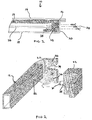
- Figure 1 shows a section of part of a vehicle door in plan view, and
- Figure 2 shows a perspective view of a strengthening structure and a latch mechanism according to the invention.
-
- Figure 1 schematically shows in plan view that part of a
vehicle door 10 near to thedoor latch mechanism 22. The door comprises a strengtheningstructure 12 housed within anouter door skin 16 and aninner door skin 18. The strengtheningstructure 12 is generally elongate and tubular, of hollow cross section and has aplate 14 attached to or formed at one end.Plate 14 may be attached to the strengtheningstructure 12 by various means, such as by welding or by screws (not shown).Plate 14 has -a " V-shaped" notch 34, provided to allow passage of a body mounted latch striker so that alatch mechanism 22 can function and engage the striker.Plate 14 has threeholes 26 to allow rigid attachment of thelatch mechanism 22 toplate 14 of strengtheningstructure 12.Latch mechanism 22 may take many forms but will always be housed within the door between the door skins near therim portion 20 ofinner door skin 18, in this case a rear edge of a side opening door hinged at its front edge. The rim ofdoor skin 20 also has three holes (not shown) configured to align withholes 26 inplate 14 whenlatch mechanism 22 is rigidly fixed to the door. -
Latch mechanism 22 has an engagement means comprising a protrusion 28 that co-operates with ahole 32 in strengtheningstructure 12 to allow fixing of the latch (see below). In the present embodiment protrusion 28 takes the form of a flexible spigot with deformable teeth 30, made of plastics material and attached to the latch mechanism by conventional means: This is a preferable feature that allows sufficient flexibility or toleranced play in the fit between three fixing means 24 andholes 26 etc., to insure that the fixing means 24 when fitted cause the latch to be positioned correctly relative to the strengtheningstructure 12, optionally in conjunction with other elements such as a tongue and change slot or hook (not shown). The fixing means of the present embodiment are threaded fasteners in the form of screws. - Thus, during assembly of the door the
outer door skin 16 is attached to the strengtheningstructure 12, thelatch mechanism 22 is non-rigidly attached to the strengtheningstructure 12 by means of engagement means 28 (spigot) and then theinner door skin 22 is positioned against the inside of the strengtheningstructure 12 for fixing. Theinner skin 18 is fixed in part to the strengtheningstructure 12 by threescrews 24 that pass through the holes in therim 20 of the inner skin, through theholes 26 inplate 14 and thereby into threaded bores in the latch mechanism (not shown). On tighteningscrews 24latch mechanism 22 is rigidly fixed to stengtheningstructure 12 in the correct position relative to the rest of the door. - The door will also typically have a
glass window 36 retractably mounted on guide channels 38 (only one shown).Guide channels 38 may be formed part of a frame strengthening structure, for example using a frame with a "U-shaped" cross section. - The strengthening structure may take a variety of forms, for example it may comprise a frame located between the inner and outer door skin near the edge of the door. It may comprise such a frame with one or more side impact bars. The cross section of the frame members/bars can be other than tubular, for example "L" or "U" shaped. In another aspect,
plate 14 may be formed as an integral part of strengtheningstructure 12 and/or strengtheningstructure 12 may itself be formed by joining more than one elongated component. - The protrusion 28 may be formed or attached to either the latch mechanism or the strengthening structure. The protrusion may take the form of a tongue or a hook. The generally cylindrically shaped spigot 28 is described above by way of example only. The spigot can have various cross section shapes and may be tubular or non tubular in form. The deformable teeth 30 may be replaced by other fixing means such as deformable prongs that engage the inside rim of
fixing hole 32. - Alternatively, but less preferably, the latch mechanism may be non-rigidly held in place to the strengthening structure by a clipping arrangement between the latch mechanism and the strengthening structure, such an arrangement not requiring a slot, aperture or a recess that cooperate with a protrusion.
- The invention conveniently allows a latch mechanism to be loosely and temporarily held in position ready for rigid fixing at the time of fixing the inner door skin. The door of the invention has enhanced resistance to forced opening of the lock during a collision as the lock mechanism is directly fixed to a strengthening structure designed to resist impact, especially side impact. It is important to prevent doors opening during a collision as the structure is significantly more rigid if the door remains in place and is therefore able to stiffen the side structure of the vehicle.
Claims (13)
- A vehicle door (10) comprising a strengthening structure (12), an inner door skin (18) and a latch mechanism (22) to be housed within the door, said mechanism having engagement means (28) that co-operate with the strengthening structure to allow the mechanism to be presented for rigid fixing within the door after the inner skin has been positioned relative to the strengthening structure; wherein at least one fixing means (24) rigidly holds both the inner door skin and the latch mechanism to the strengthening structure.
- A vehicle door according to Claim 1 wherein the strengthening structure is rigidly held between the latch mechanism and the inner door skin.
- A vehicle door according to Claim 2 wherein the strengthening structure comprises an elongated section and a plate section (14) formed in a plane generally orthogonal to the longitudinal axis of the elongate section.
- A vehicle door according to Claim 3 wherein the plate is attached to the strengthening structure.
- A vehicle door according to Claim 1 or 2 wherein the fixing means engages a rim portion (20) of the inner door skin.
- A vehicle door according to any preceding claim wherein the engagement means comprises a protrusion on the latch mechanism with a corresponding slot, aperture (32) or recess in the strengthening structure.
- A vehicle door according to any of Claims 1 to 5 wherein the engagement means comprises a protrusion on the strengthening structure with a corresponding slot, aperture or recess in the latch mechanism.
- A vehicle door according to Claim 6 or 7 wherein the protrusion comprises a tongue or a hook, or a screw or a spigot.
- A vehicle door according to Claim 8 wherein the protrusion may be flexed to assist engagement in the slot, aperture or recess.
- A vehicle door according to Claim 6 or 7 wherein the protrusion is a flexible screw or spigot with ratchet teeth.
- A vehicle door according to any preceding claim having an outer skin (16) adjacent to the strengthening structure.
- A latch mechanism (22), adapted to be fixed to both a door strengthening structure (12) and an inner door skin (18), having engagement means (28) that co-operate with the strengthening structure to allow the mechanism to be presented for rigid fixing within a vehicle door (10) after the inner skin has been positioned relative to the strengthening structure; and wherein a single fixing means (24) may rigidly hold both the latch mechanism and an inner door skin to the strengthening structure.
- A method of fixing a latch mechanism (22) to a vehicle door (10) comprising the steps of:(a) non rigidly attaching a latch mechanism, so that it is positioned for subsequent rigid fixing, to a strengthening structure (12) using engagement means (28) fixed to the latch mechanism that co-operate with the strengthening structure;(b) positioning an inner door skin (18) relative to the strengthening structure; and(c) rigidly fixing both the inner door skin and the latch mechanism to the strengthening structure by at least one fixing means (24).
Applications Claiming Priority (2)
| Application Number | Priority Date | Filing Date | Title |
|---|---|---|---|
| GBGB0201215.1A GB0201215D0 (en) | 2002-01-21 | 2002-01-21 | Vehicle door assembly |
| GB0201215 | 2002-01-21 |
Publications (2)
| Publication Number | Publication Date |
|---|---|
| EP1329350A2 true EP1329350A2 (en) | 2003-07-23 |
| EP1329350A3 EP1329350A3 (en) | 2005-06-15 |
Family
ID=9929383
Family Applications (1)
| Application Number | Title | Priority Date | Filing Date |
|---|---|---|---|
| EP02258630A Withdrawn EP1329350A3 (en) | 2002-01-21 | 2002-12-13 | Vehicle door assembly with latch mechanism |
Country Status (3)
| Country | Link |
|---|---|
| US (1) | US6925759B2 (en) |
| EP (1) | EP1329350A3 (en) |
| GB (1) | GB0201215D0 (en) |
Cited By (3)
| Publication number | Priority date | Publication date | Assignee | Title |
|---|---|---|---|---|
| GB2405618A (en) * | 2003-09-05 | 2005-03-09 | Ford Global Tech Llc | Side impact assembly for a motor vehicle door |
| FR2946285A1 (en) * | 2009-06-05 | 2010-12-10 | Peugeot Citroen Automobiles Sa | DOOR FOR VEHICLE COMPRISING A RIGIDIFICATION REINFORCEMENT AND ASSOCIATED MOUNTING METHOD. |
| US20180073281A1 (en) * | 2015-04-08 | 2018-03-15 | Kiekert Ag | Motor vehicle door lock |
Families Citing this family (2)
| Publication number | Priority date | Publication date | Assignee | Title |
|---|---|---|---|---|
| WO2014162900A1 (en) * | 2013-04-03 | 2014-10-09 | 本田技研工業株式会社 | Vehicle door |
| DE202015105205U1 (en) * | 2015-10-02 | 2017-01-09 | BROSE SCHLIEßSYSTEME GMBH & CO. KG | Door module for installation in a motor vehicle door |
Citations (1)
| Publication number | Priority date | Publication date | Assignee | Title |
|---|---|---|---|---|
| WO2001023201A1 (en) | 1999-09-28 | 2001-04-05 | Meritor Automotive Gmbh | Vehicle door |
Family Cites Families (11)
| Publication number | Priority date | Publication date | Assignee | Title |
|---|---|---|---|---|
| JPS60980Y2 (en) | 1978-08-29 | 1985-01-12 | 日産自動車株式会社 | Door structure with sash |
| JPS56154321A (en) * | 1980-05-01 | 1981-11-28 | Nissan Motor Co Ltd | Guard bar for automobile door |
| JPH04100730A (en) * | 1990-08-20 | 1992-04-02 | Mazda Motor Corp | Door structure of vehicle |
| US5308129A (en) * | 1990-10-24 | 1994-05-03 | General Motors Corporation | Door hardware module with latch |
| JPH05238261A (en) * | 1992-03-02 | 1993-09-17 | Johnan Seisakusho Co Ltd | Door of automobile |
| JPH06183258A (en) * | 1992-12-18 | 1994-07-05 | Johnan Seisakusho Co Ltd | Automobile door |
| US5505024A (en) * | 1993-11-22 | 1996-04-09 | Chrysler Corporation | Vehicle door assembly |
| US5364157A (en) | 1993-12-27 | 1994-11-15 | Ford Motor Company | Reinforced cargo door assembly |
| DE19654956B4 (en) * | 1996-06-04 | 2005-06-23 | Brose Fahrzeugteile Gmbh & Co. Kommanditgesellschaft, Coburg | Motor vehicle door |
| JP3410372B2 (en) * | 1998-08-31 | 2003-05-26 | アイシン精機株式会社 | Vehicle door lock operation system and vehicle door provided with the door lock operation system |
| US6205714B1 (en) | 1998-12-16 | 2001-03-27 | Delphi Technologies, Inc. | Modular vehicle door |
-
2002
- 2002-01-21 GB GBGB0201215.1A patent/GB0201215D0/en not_active Ceased
- 2002-12-13 EP EP02258630A patent/EP1329350A3/en not_active Withdrawn
-
2003
- 2003-01-21 US US10/347,817 patent/US6925759B2/en not_active Expired - Fee Related
Patent Citations (1)
| Publication number | Priority date | Publication date | Assignee | Title |
|---|---|---|---|---|
| WO2001023201A1 (en) | 1999-09-28 | 2001-04-05 | Meritor Automotive Gmbh | Vehicle door |
Cited By (5)
| Publication number | Priority date | Publication date | Assignee | Title |
|---|---|---|---|---|
| GB2405618A (en) * | 2003-09-05 | 2005-03-09 | Ford Global Tech Llc | Side impact assembly for a motor vehicle door |
| GB2405618B (en) * | 2003-09-05 | 2006-08-23 | Ford Global Tech Llc | A pusher assembly for a motor vehicle door |
| FR2946285A1 (en) * | 2009-06-05 | 2010-12-10 | Peugeot Citroen Automobiles Sa | DOOR FOR VEHICLE COMPRISING A RIGIDIFICATION REINFORCEMENT AND ASSOCIATED MOUNTING METHOD. |
| US20180073281A1 (en) * | 2015-04-08 | 2018-03-15 | Kiekert Ag | Motor vehicle door lock |
| US11131125B2 (en) * | 2015-04-08 | 2021-09-28 | Kiekert Ag | Motor vehicle door lock |
Also Published As
| Publication number | Publication date |
|---|---|
| US6925759B2 (en) | 2005-08-09 |
| GB0201215D0 (en) | 2002-03-06 |
| US20030140567A1 (en) | 2003-07-31 |
| EP1329350A3 (en) | 2005-06-15 |
Similar Documents
| Publication | Publication Date | Title |
|---|---|---|
| EP1243471B1 (en) | Vehicle mirror device assembly | |
| DE69020071T2 (en) | Airbag device for a motor vehicle. | |
| EP1415851B1 (en) | Vehicle seat | |
| EP0691230A1 (en) | Visor clip assembly and releasable fastener | |
| US6176660B1 (en) | Releasable fastener with lateral stabilizing brace members and latch legs carrying fastener insertion guide | |
| EP1060090B1 (en) | Door module with outside door handle | |
| EP1329350A2 (en) | Vehicle door assembly with latch mechanism | |
| DE10144166B4 (en) | Lock for a motor vehicle door | |
| DE102004023396A1 (en) | Device for fixing cladding part, especially interior cladding part, to semifinished component, especially motor vehicle door, has clamping element with which cladding part is held at fixed distance from semifinished component | |
| US10350975B2 (en) | Vehicle component | |
| US20180072243A1 (en) | Door frame of a motor vehicle | |
| US20070126259A1 (en) | Unit carrier comprising an integrated lock fixing system for a motor vehicle door | |
| US20170305363A1 (en) | Sliding joint applique | |
| US20250137299A1 (en) | Door structure for a motor vehicle | |
| DE19717906B4 (en) | Device for mounting a motor vehicle door lock | |
| JP5427230B2 (en) | Door lock mechanism mounting jig | |
| JP3712283B2 (en) | Instrument panel assembly | |
| KR20010098717A (en) | Locking device for a vehicle door | |
| JPH081158Y2 (en) | Seat belt support structure | |
| US20080211258A1 (en) | Door handle reinforcement plate | |
| KR101764089B1 (en) | A Door Lock Latch Back with Solid Coupling Structure | |
| JP4592951B2 (en) | Roof molding equipment | |
| JP3506110B2 (en) | Mounting structure for vehicle exterior parts | |
| US10179551B2 (en) | Sliding joint applique | |
| US20180272844A1 (en) | Vehicle door latch reinforcement assembly |
Legal Events
| Date | Code | Title | Description |
|---|---|---|---|
| PUAI | Public reference made under article 153(3) epc to a published international application that has entered the european phase |
Free format text: ORIGINAL CODE: 0009012 |
|
| AK | Designated contracting states |
Designated state(s): AT BE BG CH CY CZ DE DK EE ES FI FR GB GR IE IT LI LU MC NL PT SE SI SK TR |
|
| AX | Request for extension of the european patent |
Extension state: AL LT LV MK RO |
|
| PUAL | Search report despatched |
Free format text: ORIGINAL CODE: 0009013 |
|
| AK | Designated contracting states |
Kind code of ref document: A3 Designated state(s): AT BE BG CH CY CZ DE DK EE ES FI FR GB GR IE IT LI LU MC NL PT SE SI SK TR |
|
| AX | Request for extension of the european patent |
Extension state: AL LT LV MK RO |
|
| AKX | Designation fees paid | ||
| REG | Reference to a national code |
Ref country code: DE Ref legal event code: 8566 |
|
| STAA | Information on the status of an ep patent application or granted ep patent |
Free format text: STATUS: THE APPLICATION IS DEEMED TO BE WITHDRAWN |
|
| 18D | Application deemed to be withdrawn |
Effective date: 20051216 |