EP1329278A2 - Drawn arc welding method and drawn-arc-weld ferrule - Google Patents
Drawn arc welding method and drawn-arc-weld ferrule Download PDFInfo
- Publication number
- EP1329278A2 EP1329278A2 EP03075030A EP03075030A EP1329278A2 EP 1329278 A2 EP1329278 A2 EP 1329278A2 EP 03075030 A EP03075030 A EP 03075030A EP 03075030 A EP03075030 A EP 03075030A EP 1329278 A2 EP1329278 A2 EP 1329278A2
- Authority
- EP
- European Patent Office
- Prior art keywords
- drawn
- arc
- ferrule
- weld
- parts
- Prior art date
- Legal status (The legal status is an assumption and is not a legal conclusion. Google has not performed a legal analysis and makes no representation as to the accuracy of the status listed.)
- Granted
Links
Images

Classifications
-
- B—PERFORMING OPERATIONS; TRANSPORTING
- B23—MACHINE TOOLS; METAL-WORKING NOT OTHERWISE PROVIDED FOR
- B23K—SOLDERING OR UNSOLDERING; WELDING; CLADDING OR PLATING BY SOLDERING OR WELDING; CUTTING BY APPLYING HEAT LOCALLY, e.g. FLAME CUTTING; WORKING BY LASER BEAM
- B23K9/00—Arc welding or cutting
- B23K9/20—Stud welding
- B23K9/207—Features related to studs
- B23K9/208—Ferrules, e.g. for confining molten material
Definitions
- the present invention relates generally to welding methods and apparatus, and more particularly to a drawn arc welding method and a drawn-arc-weld ferrule.
- first and second parts together such as a steel attachment ring and a steel rod of a vehicle shock absorber
- welding such as drawn arc welding.
- the attachment ring is connected to a grounded drawn-arc-weld electrode
- the rod is connected to a positive drawn-arc-weld electrode.
- a tenon on the rod is brought in contact with the ring and is then withdrawn to create a welding arc which melts portions of the rod and the ring creating a weld puddle which leads to the welding together of the parts.
- a conventional ceramic ferrule is used to contain the weld puddle when the diameter of the tenon is larger than about six to eight millimeters or when a weldment dimension is larger than about ten millimeters when drawn arc welding is performed with or without one or both of the parts having a tenon.
- Conventional grooves in the ceramic ferrule allow gases created during welding to escape. Ceramic drawn arc weld ferrules are designed not to melt during welding.
- a conventional one-piece ceramic drawn-arc weld ferrule is broken up to be removed from the welded parts, and the broken ferrule pieces are then discarded.
- Conventional ceramic drawn-arc-weld ferrules are known which have been split in half creating two separate segments, wherein each segment is mounted to a ferrule holder.
- the ferrule holders are moved toward each other to bring the segments together to create the ferrule for surrounding the weld zone for drawn arc welding.
- the ferrule holders are moved away from each other after the parts have been welded together allowing removal of the welded parts from the welding machine.
- Such two-piece ceramic drawn-arc-weld ferrules are reusable for only a few hundred welds and are very expensive to machine or sinter to the necessary shapes.
- Conventional ferrule holders are known which contain passages for directing gases (such as a mixture of argon and carbon dioxide) to shield the weld zone and stabilize the welding arc.
- a first method of the invention is for attaching first and second parts together and includes steps a) through e).
- Step a) includes positioning the first and second parts for drawn arc welding the first and second parts together.
- Step b) includes obtaining a drawn-arc-weld ferrule comprising metal.
- the terminology "comprising metal” includes comprising a metal or comprising a plurality of metals.
- Step c) includes positioning the drawn-arc-weld ferrule for use in drawn-arc-welding together the positioned first and second parts.
- Step d) includes cooling the drawn-arc-weld ferrule.
- Step e) includes drawn arc welding the positioned first and second parts together using the positioned drawn-arc-weld ferrule.
- a second method of the invention is for attaching first and second parts together and includes steps a) through e).
- Step a) includes positioning the first and second parts for drawn arc welding the first and second parts together.
- Step b) includes obtaining a drawn-arc-weld ferrule including separate segments each consisting essentially of metal or metal alloy or both, and each having a melting point lower than a maximum welding temperature reached during drawn arc welding together of the first and second parts.
- Step c) includes positioning together the segments to create a ferrule shape for use in drawn-arc-welding together the disposed first and second parts.
- Step d) includes cooling each of the segments.
- Step e) includes drawn arc welding the positioned first and second parts together using the positioned segments.
- a first expression of an embodiment of the invention is for a drawn-arc-weld ferrule which includes metal.
- a second expression of an embodiment of the invention is for a drawn-arc-weld ferrule including separate segments each including metal.
- a drawn-arc-weld ferrule including metal such as a copper ferrule
- a drawn-arc-weld ferrule which is inexpensive to machine to the necessary shapes.
- cooling the ferrule will prevent the ferrule from melting from the heat generated by drawn arc welding and should allow the ferrule to be reused for several thousand times to drawn arc weld together parts such as steel attachment rings and steel rods of vehicle shock absorbers.
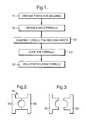
- a first method of the invention is for attaching first and second parts 10 and 12 (seen in Figure 4) together and includes steps a) through e).
- Step a) is labeled as "Dispose Parts For Welding" in block 14 of Figure 1.
- Step a) includes disposing the first and second parts 10 and 12 for drawn arc welding the first and second parts 10 and 12 together.
- Step b) is labeled as "Obtain A Weld Ferrule" in block 16 of Figure 1.
- Step b) includes obtaining a drawn-arc-weld ferrule 18 comprising metal. It is noted that a metal alloy comprises metal.
- Step c) is labeled as "Dispose Ferule For Welding Parts" in block 20 of Figure 1.
- Step c) includes disposing the drawn-arc-weld ferrule 18 for use in drawn-arc-welding together the disposed first and second parts 10 and 12.
- Step d) is labeled as "Cool The Ferrule” in block 22 of Figure 1.
- Step d) includes cooling the drawn-arc-weld ferrule 18.
- Step e) is labeled as "Weld Parts Using Ferrule” in block 24 of Figure 1.
- Step e) includes drawn arc welding the disposed first and second parts 10 and 12 together using the disposed drawn-arc-weld ferrule 18.
- steps a) through e) can be performed in any appropriate order and that appropriate steps can be performed simultaneously. In one procedure, steps d) and e) are performed simultaneously. In the same or a different procedure, step b) is performed before step a). Other step arrangements are left to the artisan.
- the drawn-arc-weld ferrule 18 would melt from the heat generated by the drawn arc welding of step e) without the cooling of step d).
- the drawn-arc-weld ferrule 18 has a thermal conductivity at least equal to the thermal conductivity of copper.
- the drawn-arc-weld ferrule 18 consists essentially of one or more metals and/or one or more metal alloys.
- the drawn-arc-weld ferrule 18 comprises copper.
- the drawn-arc-weld ferrule 18 consists essentially of copper.
- the drawn-arc-weld ferrule 18 consists of copper.
- the drawn-arc-weld ferrule 18 includes a plurality of separate segments 26 and 28, wherein the method also includes the step of attaching each of the segments 26 and 28 to a separate ferrule holder (not shown), and wherein step c) includes bringing the segments 26 and 28 together through movement of at least one of the ferrule holders.
- the drawn-arc-weld ferrule 18 consists of two segments 26 and 28. The shape of the drawn-arc-weld ferrule 18 is left to the artisan to meet the needs of a particular weldment.
- each of the ferrule holders has a coolant passageway, wherein step d) includes passing coolant through the coolant passageway of each ferrule holder.
- heat transfer is from the segment to the corresponding ferrule holder (which typically is made of the same material as the segment) to the coolant.
- the coolant consists essentially of water.
- Other types of liquid coolant can be used.
- each of the segments 26 and 28 has a coolant passageway (not shown), and step d) includes passing coolant through the coolant passageway of each segment.
- the coolant consists essentially of water.
- the first and second parts 10 and 12 consist essentially of steel.
- the first part 10 is a rod 30 of a vehicle shock absorber
- the second part 12 is an attachment ring 32.
- a top cover plate 34 surrounds the tenon 36 of the rod 30 as shown in Figure 4. It is noted that the tenon 36 is not required for drawn arc welding.
- Other examples of first and second parts 10 and 12 are left to the artisan.
- step a) includes moving the first part 10 (e.g., the rod 30) along a first direction 38 toward the second part 12 (e.g., the attachment ring 32), wherein step e) creates a weldment extending at least ten millimeters in a direction substantially transverse to the first direction 38.
- the weldment has a substantially circular shape having a diameter of at least ten millimeters. It is noted that Figure 4 is a pre-weld figure and does not show the weldment, but that such weldment would substantially fill the weld-puddle containment cavity 40 shown in Figure 4.
- gas-outlet grooves in the segments 26 and 28 of the drawn-arc-weld ferrule 18 have been omitted from the figures for clarity, such grooves being well known to the artisan.
- ferrule holders can contain passages for directing gases (such as a mixture of argon and carbon dioxide) to shield the weld zone and stabilize the welding arc, as also is known to the artisan.
- a second method of the invention (which can be described from the same Figure 1 block diagram as the first method) is for attaching first and second parts 10 and 12 (seen in Figure 4) together and includes steps a) through e).
- Step a) is labeled as "Dispose Parts For Welding" in block 14 of Figure 1.
- Step a) includes disposing the first and second parts 10 and 12 for drawn arc welding the first and second parts 10 and 12 together.
- Step b) is labeled as "Obtain A Weld Ferrule" in block 16 of Figure 1.
- Step b) includes obtaining a drawn-arc-weld ferrule 18 including a plurality of separate segments 26 and 28 each consisting essentially of metal or metal alloy or both, and each having a melting point lower than a maximum welding temperature reached during drawn arc welding together of the first and second parts 10 and 12.
- the terminology “consisting essentially of metal” includes consisting essentially of a metal or a plurality of metals.
- the terminology “consisting essentially of metal alloy” includes consisting essentially of a metal alloy or a plurality of metal alloys.
- Step c) is labeled as "Dispose Ferule For Welding Parts" in block 20 of Figure 1.
- Step c) includes disposing together the segments 26 and 28 to create a ferrule shape for use in drawn-arc-welding together the disposed first and second parts 10 and 12.
- Step d) is labeled as "Cool The Ferrule” in block 22 of Figure 1.
- Step d) includes cooling each of the segments 26 and 28.
- Step e) is labeled as "Weld Parts Using Ferrule” in block 24 of Figure 1.
- Step e) includes drawn arc welding the disposed first and second parts 10 and 12 together using the disposed segments 26 and 28.
- each segment 26 and 28 consists essentially of copper. It is noted that the previous discussion of the first method is applicable to the second method.
- a first expression of an embodiment of the invention is for a drawn-arc-weld ferrule 18 comprising metal. It is noted that a metal alloy comprises metal.
- a second expression of an embodiment of the invention is for a drawn-arc-weld ferrule 18 comprising a plurality of separate segments 26 and 28 each comprising metal.
- the drawn-arc-weld ferrule 18 has a thermal conductivity at least equal to the thermal conductivity of copper.
- each segment 26 and 28 consists essentially of copper.
- a drawn-arc-weld ferrule including metal such as a copper ferrule
- a drawn-arc-weld ferrule which is inexpensive to machine to the necessary shapes.
- cooling the ferrule will prevent the ferrule from melting from the heat generated by drawn arc welding and should allow the ferrule to be reused for several thousand times to drawn arc weld together parts such as steel attachment rings and steel rods of vehicle shock absorbers.
- a copper ferrule has a much higher thermal shock resistance than a conventional ceramic ferrule.
Landscapes
- Engineering & Computer Science (AREA)
- Physics & Mathematics (AREA)
- Plasma & Fusion (AREA)
- Mechanical Engineering (AREA)
- Arc Welding In General (AREA)
- Butt Welding And Welding Of Specific Article (AREA)
Abstract
Description
Conventional grooves in the ceramic ferrule allow gases created during welding to escape. Ceramic drawn arc weld ferrules are designed not to melt during welding.
Claims (20)
- A method for attaching first and second parts (10 and 12) together comprising the steps of:a) disposing the first and second parts for drawn arc welding the first and second parts together;b) obtaining a drawn-arc-weld ferrule (18) comprising metal;c) disposing the drawn-arc-weld ferrule for use in drawn-arc-welding together the disposed first and second parts;d) cooling the drawn-arc-weld ferrule; ande) drawn arc welding the disposed first and second parts together using the disposed drawn-arc-weld ferrule.
- The method of claim 1, wherein the drawn-arc-weld ferrule would melt from the heat generated by the drawn arc welding of step e) without the cooling of step d).
- The method of claim 1, wherein the drawn-arc-weld ferrule has a thermal conductivity at least equal to the thermal conductivity of copper.
- The method of claim 1, wherein the drawn-arc-weld ferrule comprises copper.
- The method of claim 4, wherein the drawn-arc-weld ferrule consists essentially of copper.
- The method of claim 5, wherein the drawn-arc-weld ferrule consists of copper.
- The method of claim 1, wherein the drawn-arc-weld ferrule includes a plurality of separate segments (26 and 28), wherein the method also includes the step of attaching each of the segments to a separate ferrule holder, and wherein step c) includes bringing the segments together through movement of at least one of the ferrule holders.
- The method of claim 7, wherein the drawn-arc-weld ferrule consists of two segments.
- The method of claim 7, wherein each of the ferrule holders has a coolant passageway, and wherein step d) includes passing coolant through the coolant passageway of each ferrule holder.
- The method of claim 9, wherein the coolant consists essentially of water.
- The method of claim 7, wherein each of the segments has a coolant passageway, and wherein step d) includes passing coolant through the coolant passageway of each segment.
- The method of claim 11, wherein the coolant consists essentially of water.
- The method of claim 1, wherein the first and second parts consist essentially of steel.
- The method of claim 1, wherein step a) includes moving the first part along a first direction (38) toward the second part, and wherein step e) creates a weldment extending at least ten millimeters in a direction substantially transverse to the first direction.
- The method of claim 1, wherein the weldment has a substantially circular shape having a diameter of at least ten millimeters.
- A method for attaching first and second parts (10 and 12) together comprising the steps of:a) disposing the first and second parts for drawn arc welding the first and second parts together;b) obtaining a drawn-arc-weld ferrule (18) including a plurality of separate segments (26 and 28) each consisting essentially of metal or metal alloy or both, and each having a melting point lower than a maximum welding temperature reached during drawn arc welding together of the first and second parts;c) disposing together the segments to create a ferrule shape for use in drawn-arc-welding together the disposed first and second parts;d) cooling each of the segments; ande) drawn arc welding the disposed first and second parts together using the disposed segments.
- The method of claim 16, wherein each segment consists essentially of copper.
- A drawn-arc-weld ferrule (18) comprising metal.
- A drawn-arc-weld ferrule (18) comprising a plurality of separate segments (26 and 28) each comprising metal.
- The drawn-arc-weld ferrule of claim 19, wherein each segment consists essentially of copper.
Applications Claiming Priority (2)
| Application Number | Priority Date | Filing Date | Title |
|---|---|---|---|
| US10/050,505 US6667455B2 (en) | 2002-01-16 | 2002-01-16 | Drawn arc welding method and drawn-arc-weld ferrule |
| US50505 | 2002-01-16 |
Publications (3)
| Publication Number | Publication Date |
|---|---|
| EP1329278A2 true EP1329278A2 (en) | 2003-07-23 |
| EP1329278A3 EP1329278A3 (en) | 2005-11-02 |
| EP1329278B1 EP1329278B1 (en) | 2008-01-02 |
Family
ID=21965611
Family Applications (1)
| Application Number | Title | Priority Date | Filing Date |
|---|---|---|---|
| EP03075030A Expired - Lifetime EP1329278B1 (en) | 2002-01-16 | 2003-01-07 | Drawn arc welding method and drawn-arc-weld ferrule |
Country Status (3)
| Country | Link |
|---|---|
| US (1) | US6667455B2 (en) |
| EP (1) | EP1329278B1 (en) |
| DE (1) | DE60318338T2 (en) |
Family Cites Families (14)
| Publication number | Priority date | Publication date | Assignee | Title |
|---|---|---|---|---|
| FR1229756A (en) * | 1958-09-08 | 1960-09-09 | ||
| US3182173A (en) * | 1962-05-21 | 1965-05-04 | Dash Edward | Welding stud and ferrule construction for arc welding |
| US3555238A (en) * | 1967-04-26 | 1971-01-12 | Omark Industries Inc | Permanent arc shield |
| US3557339A (en) * | 1969-04-03 | 1971-01-19 | Warren Fastener Corp | Nonconsumable, reusable stud welding ferrule |
| US3597573A (en) * | 1970-01-02 | 1971-08-03 | Warren Fastener Corp | Welding stud and ferrule-stud assemblies |
| US4117297A (en) * | 1975-06-26 | 1978-09-26 | Trw Inc. | Ferrule for stud welding |
| US4306137A (en) * | 1978-05-16 | 1981-12-15 | Trw Inc. | Method and apparatus for conducting smut-free stud welding |
| US4201904A (en) * | 1978-05-22 | 1980-05-06 | Geo. P. Reintjes Co., Inc. | Air cooled head for stud welding gun |
| US4317020A (en) * | 1979-09-14 | 1982-02-23 | Trw Inc. | Apparatus for conducting smut-free welding |
| KR930006434B1 (en) * | 1989-11-13 | 1993-07-16 | 오까베 가부시끼가이샤 | Arc stud welding machine |
| JPH03155494A (en) * | 1989-11-13 | 1991-07-03 | Okabe Co Ltd | Welding assisting material |
| GB2277047A (en) * | 1993-04-14 | 1994-10-19 | Chun Yu Works & Co Limited | Arc shields |
| JP3032686B2 (en) * | 1994-10-17 | 2000-04-17 | 新日本製鐵株式会社 | Reinforced splice composite backing material |
| US5896960A (en) * | 1997-08-25 | 1999-04-27 | General Motors Corporation | Welded rod fitting damper manufacture |
-
2002
- 2002-01-16 US US10/050,505 patent/US6667455B2/en not_active Expired - Lifetime
-
2003
- 2003-01-07 DE DE60318338T patent/DE60318338T2/en not_active Expired - Lifetime
- 2003-01-07 EP EP03075030A patent/EP1329278B1/en not_active Expired - Lifetime
Also Published As
| Publication number | Publication date |
|---|---|
| EP1329278A3 (en) | 2005-11-02 |
| US20030132203A1 (en) | 2003-07-17 |
| DE60318338T2 (en) | 2008-12-11 |
| DE60318338D1 (en) | 2008-02-14 |
| US6667455B2 (en) | 2003-12-23 |
| EP1329278B1 (en) | 2008-01-02 |
Similar Documents
| Publication | Publication Date | Title |
|---|---|---|
| US5719369A (en) | Stress corrosion crack repair by plasma arc welding underwater welding | |
| US5710405A (en) | Method for developing residual compressive stress in stainless steel and nickel base superalloys | |
| JP5602458B2 (en) | Method for joining two metal parts by a tungsten-inert gas welding method and apparatus for carrying out the method | |
| US6984801B2 (en) | Method of closing a hole in a gas turbine blade top by laser welding | |
| JP6082740B2 (en) | Casing flange hole resistance welding repair method | |
| US5393948A (en) | Open faced trailing welding shield | |
| KR20070052766A (en) | How to join the exhaust system and exhaust system components | |
| US6667455B2 (en) | Drawn arc welding method and drawn-arc-weld ferrule | |
| KR20180037615A (en) | Support Device of Ends for Butt Joint Welding | |
| US5329089A (en) | Plasma arc welding weld imaging | |
| KR20170096643A (en) | Support Device of Ends for Butt Joint Welding | |
| US4264801A (en) | Method of welding tube to header of heat exchanger | |
| US20050230379A1 (en) | System and method for heating a workpiece during a welding operation | |
| CN217044959U (en) | Probe anchor clamps of brazing | |
| JPH0347952B2 (en) | ||
| JP4317598B2 (en) | Method of generating residual compressive stress in stainless steel and nickel-base superalloy and stress corrosion crack repair by underwater welding | |
| EP0418392A1 (en) | Method and consumable electrode for electric arc welding of metal parts | |
| CN213437735U (en) | Welding rod clamping device | |
| CN212823624U (en) | Be used for welded revolving stage | |
| US20240286231A1 (en) | Continuously cooled weld head | |
| Drimal et al. | The quality improvement of welded joints of die-cast Al alloys using oscillation and current modulation of the electron beam | |
| CN210848920U (en) | Adjustable welding gun | |
| Chen et al. | Robotic Welding Processes | |
| JP2000024780A (en) | TIG welding torch for narrow part and welding method using the torch | |
| JPH08118042A (en) | Double pipe diffusion bonding method |
Legal Events
| Date | Code | Title | Description |
|---|---|---|---|
| PUAI | Public reference made under article 153(3) epc to a published international application that has entered the european phase |
Free format text: ORIGINAL CODE: 0009012 |
|
| AK | Designated contracting states |
Designated state(s): AT BE BG CH CY CZ DE DK EE ES FI FR GB GR HU IE IT LI LU MC NL PT SE SI SK TR |
|
| AX | Request for extension of the european patent |
Extension state: AL LT LV MK RO |
|
| PUAL | Search report despatched |
Free format text: ORIGINAL CODE: 0009013 |
|
| AK | Designated contracting states |
Kind code of ref document: A3 Designated state(s): AT BE BG CH CY CZ DE DK EE ES FI FR GB GR HU IE IT LI LU MC NL PT SE SI SK TR |
|
| AX | Request for extension of the european patent |
Extension state: AL LT LV MK RO |
|
| RIC1 | Information provided on ipc code assigned before grant |
Ipc: 7B 23K 9/00 A Ipc: 7B 23K 9/20 B Ipc: 7B 23K 37/06 B |
|
| 17P | Request for examination filed |
Effective date: 20060502 |
|
| AKX | Designation fees paid |
Designated state(s): DE FR GB IT |
|
| GRAP | Despatch of communication of intention to grant a patent |
Free format text: ORIGINAL CODE: EPIDOSNIGR1 |
|
| GRAS | Grant fee paid |
Free format text: ORIGINAL CODE: EPIDOSNIGR3 |
|
| GRAA | (expected) grant |
Free format text: ORIGINAL CODE: 0009210 |
|
| AK | Designated contracting states |
Kind code of ref document: B1 Designated state(s): DE FR GB IT |
|
| REG | Reference to a national code |
Ref country code: GB Ref legal event code: FG4D |
|
| REF | Corresponds to: |
Ref document number: 60318338 Country of ref document: DE Date of ref document: 20080214 Kind code of ref document: P |
|
| ET | Fr: translation filed | ||
| PLBE | No opposition filed within time limit |
Free format text: ORIGINAL CODE: 0009261 |
|
| STAA | Information on the status of an ep patent application or granted ep patent |
Free format text: STATUS: NO OPPOSITION FILED WITHIN TIME LIMIT |
|
| 26N | No opposition filed |
Effective date: 20081003 |
|
| PG25 | Lapsed in a contracting state [announced via postgrant information from national office to epo] |
Ref country code: IT Free format text: LAPSE BECAUSE OF FAILURE TO SUBMIT A TRANSLATION OF THE DESCRIPTION OR TO PAY THE FEE WITHIN THE PRESCRIBED TIME-LIMIT Effective date: 20080102 |
|
| REG | Reference to a national code |
Ref country code: FR Ref legal event code: PLFP Year of fee payment: 14 |
|
| REG | Reference to a national code |
Ref country code: FR Ref legal event code: PLFP Year of fee payment: 15 |
|
| REG | Reference to a national code |
Ref country code: GB Ref legal event code: 732E Free format text: REGISTERED BETWEEN 20170727 AND 20170802 |
|
| REG | Reference to a national code |
Ref country code: FR Ref legal event code: PLFP Year of fee payment: 16 |
|
| REG | Reference to a national code |
Ref country code: FR Ref legal event code: CA Effective date: 20171124 Ref country code: FR Ref legal event code: TP Owner name: BWI COMPANY LIMITED S.A., LU Effective date: 20171124 |
|
| REG | Reference to a national code |
Ref country code: DE Ref legal event code: R081 Ref document number: 60318338 Country of ref document: DE Owner name: BWI COMPANY LIMITED S.A., LU Free format text: FORMER OWNER: DELPHI TECHNOLOGIES, INC., TROY, MICH., US Ref country code: DE Ref legal event code: R082 Ref document number: 60318338 Country of ref document: DE |
|
| PGFP | Annual fee paid to national office [announced via postgrant information from national office to epo] |
Ref country code: GB Payment date: 20211118 Year of fee payment: 20 Ref country code: FR Payment date: 20211125 Year of fee payment: 20 |
|
| PGFP | Annual fee paid to national office [announced via postgrant information from national office to epo] |
Ref country code: DE Payment date: 20211116 Year of fee payment: 20 |
|
| REG | Reference to a national code |
Ref country code: DE Ref legal event code: R071 Ref document number: 60318338 Country of ref document: DE |
|
| REG | Reference to a national code |
Ref country code: GB Ref legal event code: PE20 Expiry date: 20230106 |
|
| PG25 | Lapsed in a contracting state [announced via postgrant information from national office to epo] |
Ref country code: GB Free format text: LAPSE BECAUSE OF EXPIRATION OF PROTECTION Effective date: 20230106 |