EP1328729B1 - Engine prelubrication pump assembly - Google Patents
Engine prelubrication pump assembly Download PDFInfo
- Publication number
- EP1328729B1 EP1328729B1 EP01973587A EP01973587A EP1328729B1 EP 1328729 B1 EP1328729 B1 EP 1328729B1 EP 01973587 A EP01973587 A EP 01973587A EP 01973587 A EP01973587 A EP 01973587A EP 1328729 B1 EP1328729 B1 EP 1328729B1
- Authority
- EP
- European Patent Office
- Prior art keywords
- pump
- gear
- fluid
- prelubrication
- inlet
- Prior art date
- Legal status (The legal status is an assumption and is not a legal conclusion. Google has not performed a legal analysis and makes no representation as to the accuracy of the status listed.)
- Expired - Lifetime
Links
Images


Classifications
-
- F—MECHANICAL ENGINEERING; LIGHTING; HEATING; WEAPONS; BLASTING
- F04—POSITIVE - DISPLACEMENT MACHINES FOR LIQUIDS; PUMPS FOR LIQUIDS OR ELASTIC FLUIDS
- F04C—ROTARY-PISTON, OR OSCILLATING-PISTON, POSITIVE-DISPLACEMENT MACHINES FOR LIQUIDS; ROTARY-PISTON, OR OSCILLATING-PISTON, POSITIVE-DISPLACEMENT PUMPS
- F04C14/00—Control of, monitoring of, or safety arrangements for, machines, pumps or pumping installations
- F04C14/24—Control of, monitoring of, or safety arrangements for, machines, pumps or pumping installations characterised by using valves controlling pressure or flow rate, e.g. discharge valves or unloading valves
-
- F—MECHANICAL ENGINEERING; LIGHTING; HEATING; WEAPONS; BLASTING
- F04—POSITIVE - DISPLACEMENT MACHINES FOR LIQUIDS; PUMPS FOR LIQUIDS OR ELASTIC FLUIDS
- F04C—ROTARY-PISTON, OR OSCILLATING-PISTON, POSITIVE-DISPLACEMENT MACHINES FOR LIQUIDS; ROTARY-PISTON, OR OSCILLATING-PISTON, POSITIVE-DISPLACEMENT PUMPS
- F04C14/00—Control of, monitoring of, or safety arrangements for, machines, pumps or pumping installations
- F04C14/24—Control of, monitoring of, or safety arrangements for, machines, pumps or pumping installations characterised by using valves controlling pressure or flow rate, e.g. discharge valves or unloading valves
- F04C14/26—Control of, monitoring of, or safety arrangements for, machines, pumps or pumping installations characterised by using valves controlling pressure or flow rate, e.g. discharge valves or unloading valves using bypass channels
-
- F—MECHANICAL ENGINEERING; LIGHTING; HEATING; WEAPONS; BLASTING
- F04—POSITIVE - DISPLACEMENT MACHINES FOR LIQUIDS; PUMPS FOR LIQUIDS OR ELASTIC FLUIDS
- F04C—ROTARY-PISTON, OR OSCILLATING-PISTON, POSITIVE-DISPLACEMENT MACHINES FOR LIQUIDS; ROTARY-PISTON, OR OSCILLATING-PISTON, POSITIVE-DISPLACEMENT PUMPS
- F04C2/00—Rotary-piston machines or pumps
- F04C2/08—Rotary-piston machines or pumps of intermeshing-engagement type, i.e. with engagement of co-operating members similar to that of toothed gearing
- F04C2/12—Rotary-piston machines or pumps of intermeshing-engagement type, i.e. with engagement of co-operating members similar to that of toothed gearing of other than internal-axis type
- F04C2/14—Rotary-piston machines or pumps of intermeshing-engagement type, i.e. with engagement of co-operating members similar to that of toothed gearing of other than internal-axis type with toothed rotary pistons
- F04C2/18—Rotary-piston machines or pumps of intermeshing-engagement type, i.e. with engagement of co-operating members similar to that of toothed gearing of other than internal-axis type with toothed rotary pistons with similar tooth forms
-
- F—MECHANICAL ENGINEERING; LIGHTING; HEATING; WEAPONS; BLASTING
- F01—MACHINES OR ENGINES IN GENERAL; ENGINE PLANTS IN GENERAL; STEAM ENGINES
- F01M—LUBRICATING OF MACHINES OR ENGINES IN GENERAL; LUBRICATING INTERNAL COMBUSTION ENGINES; CRANKCASE VENTILATING
- F01M5/00—Heating, cooling, or controlling temperature of lubricant; Lubrication means facilitating engine starting
- F01M5/02—Conditioning lubricant for aiding engine starting, e.g. heating
- F01M5/025—Conditioning lubricant for aiding engine starting, e.g. heating by prelubricating, e.g. using an accumulator
- F01M2005/026—Conditioning lubricant for aiding engine starting, e.g. heating by prelubricating, e.g. using an accumulator with an auxiliary pump
Definitions
- the present invention relates to an improved engine prelubrication pump which operates with an internal combustion engine; and, in particular, to an oil pump which is driven by a starter motor armature drive shaft and which pump includes an internal vent for improved pump and motor durability.
- the invention is also applicable to stand alone or supplemental prelubrication pumps.
- the fluid pump of the present invention is an improvement over pumps shown U.S. Patent Nos. 4,553,512 , 4,875,551 and 4,502,431 .
- These pumps are used to lubricate the engine prior to the initial phase of the cranking of the starter motor to turn over an engine.
- oil is used as a lubricant to allow engine parts to slide freely and easily with reduced friction.
- lubricants having high lubricity there continues to be abrasive wear between metal parts in internal engine components such as the turbocharger, camshaft, crank shaft and rocker assembly, for example. It has been known for some time that the greatest wear on internal engine parts is at the commencement of ignition cranking and engine start-up.
- the present invention provides a similar pump assembly as that disclosed in U.S. Patent 4, 553,512 to provide a selectable means for either prelubricating the engine or pumping the oil out for a quick efficient oil change. This is particularly useful to large fleet operators of vehicles which require frequent oil changes.
- the present invention provides a gear-type pump which is integrated to the starter motor of a vehicle.
- the base portion of the pump generally comprises the back or bearing end of the starter motor and includes a sealed opening through which an extended armature shaft can be mounted to rotate or power the pump gears.
- a pump housing is integrally formed on the base plate which provides a cavity in which the pump gears are mounted and includes an inlet and outlet port.
- the present invention provides a seal bore vent to the pump inlet which uses a passageway from the pump inlet into the armature shaft or pump seal bore to minimize the oil pressure at the seal during all modes of operation. This vent relieves pressure from the seal which seals the pump cavity from the motor cavity. In this way, the pump and motor are further protected from damage and their longevity enhanced. This is especially the case when a valve selector and port are provided in the pump as set forth in one of the embodiments hereof.
- the invention may include an additional port for operation of valve mechanism to permit the oil to be pumped and bypassed to the outlet port in normal operation. By rendering the valve “ineffective,” oil can be pumped to the outlet port for either prelubrication or for changing the oil of the vehicle.
- pump 10 of the present invention comprises base plate 11 which is adapted to be bolted to the back portion of a starter motor (not shown) by means of a plurality of a circumferentially positioned bolts 12.
- base plate 11 Integrally formed in base plate 11 is pump housing 13 having an elongated pump cavity 14 and central opening through which a motor or armature shaft 16 extends therein.
- Cavity 14 also includes idler shaft 17 mounted fixably to the other portion of the cavity.
- pump gears 18 and 19 Positioned within cavity 14 are pump gears 18 and 19 which are driven by armature shaft 16.
- Pump housing 13 also includes inlet port 21 and outlet port 22. These ports are connected to inlet and outlet lines (not shown). Sealingly mounted to the pump housing 13 is sealing plate 23 which seals pump cavity 14 from the outside and shaft seal 101 which seals pump cavity 14 from the motor cavity, as shown in Figure 3.
- Pump housing 13 also includes a means to reduce pressure to the seal 101.
- the means may include, for example, a vent area, channel or hole in the pump or pump housing.
- the means includes a vent 50 from the pump seal bore 102 to the pump inlet 21 which provides a passageway or otherwise connects to and is positioned within pump housing 13 on the side of inlet port 21, as shown in Figure 4.
- the vent 50 is a grooved channel connecting with armature shaft 16 or seal bore 102 of pump housing 13 and is positioned in the pump to relieve pressure from seal 101 to prevent damage to the pump and motor. In this way, vent 50 functions to minimize the oil pressure at the seal 101, as well as at seal bore 102, during all modes of operation.
- Figure 4 also shows a diagram of an embodiment of the present invention of the oil flow path through channel 28 and pressure relief through vent 50 and out suction port 21.
- vent 50 provides a self-adjusting restriction on increases to the oil pressure. Vent 50 is also applicable to stand alone or supplemental prelubrication pumps.
- sealing plate 23 includes housing 24.
- housing 24 also has a pair of bypass ports 26 and 27 which are juxtaposed for communication between inlet and outlet ports 21 and 22 respectively.
- a valve means such as for example a selector valve 30 comprised of a plug spring 31, and plunger or valvehead, is positioned in channel 28 to provide selectable opening and closing of the channel.
- Valve means 30 is preferably a mechanically or hydraulically operated valve that is opened to permit recirculation.
- an electromechanical solenoid valve which is normally biased in the open position can be used. When the valve 30 is open, oil recirculates to the inlet port 21. In systems where rotation of the gears is normal operation oil flows through channel 28 as the pump rotates during starter motor initiation of conventional crank mode.
- Valve means 30 is shown having spring 31 which biases hydraulic valve means 30 closed.
- Oil pressure or electrical means 32 such as a solenoid opens valve 30 to permit the recirculation of oil through channel 28.
- vent 50 is useful to prevent any excess pressure in the pump seal bore 102 of a pump having restricted channel.
- valve means 30 will be closed when outlet port 22 is open to permit oil to be pumped therethrough.
- Outlet port 22 may include an oil line to the engine to provide prelubrication as well known in the prior art or to a discharge receptacle, not shown, for changing the oil in the engine.
- a switch positioned in the engine compartment can be used to simultaneously activate the turning of the starter motor (without engaging the starter solenoid) so that the closed valve means 30 permits the oil to be pumped out of the engine.
- Various other arrangements can be used to control valve means 30 with oil change and/or prelubrication flow control valves (not shown) positioned at the outlet port or line.
Landscapes
- Engineering & Computer Science (AREA)
- Mechanical Engineering (AREA)
- General Engineering & Computer Science (AREA)
- Physics & Mathematics (AREA)
- Fluid Mechanics (AREA)
- Rotary Pumps (AREA)
- Lubrication Of Internal Combustion Engines (AREA)
- Compressors, Vaccum Pumps And Other Relevant Systems (AREA)
- Details And Applications Of Rotary Liquid Pumps (AREA)
Abstract
Description
- The present invention relates to an improved engine prelubrication pump which operates with an internal combustion engine; and, in particular, to an oil pump which is driven by a starter motor armature drive shaft and which pump includes an internal vent for improved pump and motor durability. The invention is also applicable to stand alone or supplemental prelubrication pumps.
- Generally, the fluid pump of the present invention is an improvement over pumps shown
U.S. Patent Nos. 4,553,512 ,4,875,551 and4,502,431 . These pumps are used to lubricate the engine prior to the initial phase of the cranking of the starter motor to turn over an engine. Typically, oil is used as a lubricant to allow engine parts to slide freely and easily with reduced friction. Notwithstanding the use of lubricants having high lubricity there continues to be abrasive wear between metal parts in internal engine components such as the turbocharger, camshaft, crank shaft and rocker assembly, for example. It has been known for some time that the greatest wear on internal engine parts is at the commencement of ignition cranking and engine start-up. During that time, there is insufficient oil pressure in the engine to provide lubrication to the various parts throughout the engine. Accordingly, for these initial moments during start-up, there is metal rubbing against metal without a sufficient lubricant interface so that deterioration in the internal engine components takes place over time. - A particularly important solution to this problem was provided by a prelubrication system disclosed in
U.S. Patent No. 4,502,431 in which oil is introduced in the engine prior to cranking and start-up. The starter motor is utilized as the means for powering the pump to provide prelubrication. In that system, the starter motor armature shaft is connected to the pump's pumping gears which are rotated to provide the pumping action to the engine to prelubricate prior to the starter motor's solenoid engaging the starter to crank the engine for start-up. One particular embodiment of the starter motor and pump combination is disclosed inU.S. Patent No. 4,553,512 which is incorporated herein by reference. - The present invention provides a similar pump assembly as that disclosed in
U.S. Patent 4, 553,512 to provide a selectable means for either prelubricating the engine or pumping the oil out for a quick efficient oil change. This is particularly useful to large fleet operators of vehicles which require frequent oil changes. - It is the object of the invention to provide a prelubrication pump assembly with a long lifetime, minimizing the oil pressure at the seal during all modes of operation.
- This object is fulfilled by an engine prelubrication pump assembly having the features disclosed in claim 1. Preferred embodiments are defined in the dependent subclaims.
- The present invention provides a gear-type pump which is integrated to the starter motor of a vehicle. As disclosed in the aforementioned prior art, the base portion of the pump generally comprises the back or bearing end of the starter motor and includes a sealed opening through which an extended armature shaft can be mounted to rotate or power the pump gears. A pump housing is integrally formed on the base plate which provides a cavity in which the pump gears are mounted and includes an inlet and outlet port. In addition, the present invention provides a seal bore vent to the pump inlet which uses a passageway from the pump inlet into the armature shaft or pump seal bore to minimize the oil pressure at the seal during all modes of operation. This vent relieves pressure from the seal which seals the pump cavity from the motor cavity. In this way, the pump and motor are further protected from damage and their longevity enhanced. This is especially the case when a valve selector and port are provided in the pump as set forth in one of the embodiments hereof.
- Additionally, the invention may include an additional port for operation of valve mechanism to permit the oil to be pumped and bypassed to the outlet port in normal operation. By rendering the valve "ineffective," oil can be pumped to the outlet port for either prelubrication or for changing the oil of the vehicle.
- Other advantages of the present invention will become apparent from a perusal of the following description of a presently preferred embodiment taken in connection with the accompanying drawings.
-
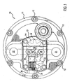
- Figure 1 is a plan view of the pump of the present invention.
- Figure 2 is a side elevation of the pump shown in Figure 1.
- Figure 3 is a sectional elevation of an embodiment of the present invention.
- Figure 4 provides a plan view diagram of a embodiment of the present invention showing oil flow path and pressure relief.
- Referring to Figures 1 and 2,
pump 10 of the present invention comprises base plate 11 which is adapted to be bolted to the back portion of a starter motor (not shown) by means of a plurality of a circumferentially positionedbolts 12. Integrally formed in base plate 11 ispump housing 13 having anelongated pump cavity 14 and central opening through which a motor orarmature shaft 16 extends therein.Cavity 14 also includesidler shaft 17 mounted fixably to the other portion of the cavity. Positioned withincavity 14 arepump gears armature shaft 16. -
Pump housing 13 also includesinlet port 21 andoutlet port 22. These ports are connected to inlet and outlet lines (not shown). Sealingly mounted to thepump housing 13 is sealingplate 23 which sealspump cavity 14 from the outside andshaft seal 101 which sealspump cavity 14 from the motor cavity, as shown in Figure 3. -
Pump housing 13 also includes a means to reduce pressure to theseal 101. The means may include, for example, a vent area, channel or hole in the pump or pump housing. In one embodiment, the means includes avent 50 from thepump seal bore 102 to thepump inlet 21 which provides a passageway or otherwise connects to and is positioned withinpump housing 13 on the side ofinlet port 21, as shown in Figure 4. In a preferred embodiment, thevent 50 is a grooved channel connecting witharmature shaft 16 orseal bore 102 ofpump housing 13 and is positioned in the pump to relieve pressure fromseal 101 to prevent damage to the pump and motor. In this way, vent 50 functions to minimize the oil pressure at theseal 101, as well as atseal bore 102, during all modes of operation. Figure 4 also shows a diagram of an embodiment of the present invention of the oil flow path throughchannel 28 and pressure relief throughvent 50 and outsuction port 21. In a preferred embodiment,vent 50 provides a self-adjusting restriction on increases to the oil pressure. Vent 50 is also applicable to stand alone or supplemental prelubrication pumps. - In a preferred
embodiment sealing plate 23 includeshousing 24. In anotherembodiment housing 24 also has a pair ofbypass ports outlet ports selector valve 30 comprised of aplug spring 31, and plunger or valvehead, is positioned inchannel 28 to provide selectable opening and closing of the channel. Valve means 30 is preferably a mechanically or hydraulically operated valve that is opened to permit recirculation. Alternatively, an electromechanical solenoid valve which is normally biased in the open position can be used. When thevalve 30 is open, oil recirculates to theinlet port 21. In systems where rotation of the gears is normal operation oil flows throughchannel 28 as the pump rotates during starter motor initiation of conventional crank mode. Valve means 30 is shown havingspring 31 which biases hydraulic valve means 30 closed. Oil pressure orelectrical means 32 such as a solenoid opensvalve 30 to permit the recirculation of oil throughchannel 28. In an embodiment,vent 50 is useful to prevent any excess pressure in the pump seal bore 102 of a pump having restricted channel. - In the presently preferred embodiment, the valve means 30 will be closed when
outlet port 22 is open to permit oil to be pumped therethrough.Outlet port 22 may include an oil line to the engine to provide prelubrication as well known in the prior art or to a discharge receptacle, not shown, for changing the oil in the engine. A switch positioned in the engine compartment can be used to simultaneously activate the turning of the starter motor (without engaging the starter solenoid) so that the closed valve means 30 permits the oil to be pumped out of the engine. Various other arrangements can be used to control valve means 30 with oil change and/or prelubrication flow control valves (not shown) positioned at the outlet port or line. - While presently preferred embodiments of the invention have been shown and described in particularity, the invention may be otherwise embodied within the scope of the appended claims.
Claims (4)
- An engine prelubrication pump assembly for use with an internal combustion engine motor, comprising:a. a pump housing (13) having a pump cavity (14);b. a first and second gear (18, 19) positioned in said cavity for pumping fluid, said first gear being operably and sealably connected to a motor shaft (16) for rotation said shaft being positioned through a bore, and said second gear (19) rotatably mounted to a second shaft (17) for geared rotation with said first gear;c. fluid inlet and outlet ports (21, 22) in communication with said cavity and adapted for connection with a source of fluid and a discharge means, respectively, andd. a shaft seal (101) which seals said pump cavity from said motor shaftcharacterized in that
an internal vent (50) is positioned between said motor shaft bore and said inlet port, wherein said vent connects said bore to said inlet port thereby decreasing the pressure in the area of said seal,
said first gear (18) being operably connected to an independent motor and in that
said prelubrication pump assembly is used as a supplemental pump or with a starter motor. - An engine prelubrication pump assembly as set forth in claim 1 wherein an armature of said starter motor comprises said means for rotating said first gear (18).
- An engine prelubrication pump assembly as set forth in claim 2 wherein said vent (50) is connected to said bore.
- An engine prelubrication pump assembly as set forth in claim 1, further including a bypass means (26, 27) positioned between said inlet and outlet ports (21, 22), said bypass means (26, 27) being selectively controllable to permit fluid pumped between the inlet and outlet ports to pass through said bypass means (26, 27), said bypass means being closed to fluid pumped by said first and second gears to flow from said inlet port (21) to said outlet port (22), during a prelubrication or a fluid change, is opened to permit the oil to cavitate in response to a selective control input during operation of the pump when said prelubrication or fluid change is not selected.
Applications Claiming Priority (3)
| Application Number | Priority Date | Filing Date | Title |
|---|---|---|---|
| US670706 | 1984-11-13 | ||
| US09/670,706 US6544008B1 (en) | 1997-07-18 | 2000-09-27 | Internal vent for reducing seal pressure in prelubrication pump assembly |
| PCT/US2001/030281 WO2002027186A1 (en) | 2000-09-27 | 2001-09-27 | Improved engine prelubrication pump assembly |
Publications (3)
| Publication Number | Publication Date |
|---|---|
| EP1328729A1 EP1328729A1 (en) | 2003-07-23 |
| EP1328729A4 EP1328729A4 (en) | 2005-01-12 |
| EP1328729B1 true EP1328729B1 (en) | 2007-06-13 |
Family
ID=24691526
Family Applications (1)
| Application Number | Title | Priority Date | Filing Date |
|---|---|---|---|
| EP01973587A Expired - Lifetime EP1328729B1 (en) | 2000-09-27 | 2001-09-27 | Engine prelubrication pump assembly |
Country Status (7)
| Country | Link |
|---|---|
| US (1) | US6544008B1 (en) |
| EP (1) | EP1328729B1 (en) |
| AT (1) | ATE364791T1 (en) |
| AU (1) | AU2001293149A1 (en) |
| DE (1) | DE60128939T2 (en) |
| ES (1) | ES2288521T3 (en) |
| WO (1) | WO2002027186A1 (en) |
Families Citing this family (12)
| Publication number | Priority date | Publication date | Assignee | Title |
|---|---|---|---|---|
| US9062575B2 (en) * | 1997-10-30 | 2015-06-23 | RPM Industries, LLC | Methods and systems for performing, monitoring and analyzing multiple machine fluid processes |
| US6988506B1 (en) | 1997-10-30 | 2006-01-24 | Rpm Industries, Inc. | Fluid transfer system |
| US7150286B2 (en) * | 1997-10-30 | 2006-12-19 | Rpm Industries, Inc. | Methods and systems for performing, monitoring and analyzing multiple machine fluid processes |
| US6708710B1 (en) * | 1997-10-30 | 2004-03-23 | Rpm Industries, Inc. | Vehicle fluid change apparatus and method |
| DE10239428A1 (en) * | 2002-08-28 | 2004-03-11 | Robert Bosch Gmbh | Gear pump |
| US6853954B2 (en) * | 2002-09-24 | 2005-02-08 | John K. Apostolides | Methods and systems for collecting and processing data in association with machine operation and maintenance |
| US20090041593A1 (en) * | 2007-08-09 | 2009-02-12 | Kabushiki Kaisha Toyota Jidoshokki | Variable displacement type gear pump |
| US8622717B1 (en) * | 2007-10-31 | 2014-01-07 | Melling Tool Company | High-performance oil pump |
| DE102010022137A1 (en) * | 2010-05-20 | 2011-11-24 | Gm Global Technology Operations Llc (N.D.Ges.D. Staates Delaware) | Pump for a lubrication system of an internal combustion engine |
| US20120258006A1 (en) * | 2011-04-11 | 2012-10-11 | Viking Pump, Inc. | External Gear Pump for Hot Cooking Oil |
| US20120269668A1 (en) * | 2011-04-19 | 2012-10-25 | Viking Pump, Inc. | Polymeric External Gear Pump for Hot Cooking Oil |
| US8984972B2 (en) | 2012-07-17 | 2015-03-24 | Cummins Ip, Inc. | Power take-off system for an internal combustion engine |
Family Cites Families (13)
| Publication number | Priority date | Publication date | Assignee | Title |
|---|---|---|---|---|
| US2887058A (en) * | 1953-05-29 | 1959-05-19 | Thompson Ramo Wooldridge Inc | Lubricated pump construction |
| US3146720A (en) * | 1961-12-06 | 1964-09-01 | Dresser Ind | Pressure relief means for pump |
| DE2810563C2 (en) * | 1978-03-10 | 1982-10-28 | Theodorus Henricus Dipl.-Ing. Delft Korse | Gear machine (pump or motor) |
| US4619588A (en) * | 1984-04-25 | 1986-10-28 | Facet Enterprises, Incorporated | Wet motor gerotor fuel pump with vapor vent valve and improved flow through the armature |
| US4553512A (en) * | 1985-01-17 | 1985-11-19 | Gerald Showman | Fluid pump assembly |
| JPH034780Y2 (en) * | 1985-02-22 | 1991-02-07 | ||
| EP0254077B1 (en) * | 1986-07-19 | 1990-11-14 | B a r m a g AG | Internal gear pump |
| DE4125128C2 (en) * | 1990-08-10 | 1994-11-24 | Barmag Barmer Maschf | Gear pump |
| US5244367A (en) * | 1990-11-30 | 1993-09-14 | Aeroquip Corporation | Gear pump with a resilient means for biasing a side wear plate |
| SE470446B (en) * | 1992-08-21 | 1994-03-28 | Electrolux Ab | Hydraulic motor provided with a by-pass line between the inlet and outlet lines, in which a by-pass line is provided with a main valve for actuating and stopping the hydraulic motor, respectively. |
| DE9217162U1 (en) * | 1992-12-16 | 1993-03-25 | Maag Pump Systems AG, Zürich | Gear pump |
| ES2110799T3 (en) * | 1995-05-24 | 1998-02-16 | Maag Pump Systems Ag | BEARING ARRANGEMENT FOR A SHAFT OF A PUMP TO IMPELLER MEDIA WITH DIFFERENT VISCOSITY. |
| DE69721092T2 (en) * | 1996-01-19 | 2003-12-11 | Aisin Seiki K.K., Kariya | Oil pumping station |
-
2000
- 2000-09-27 US US09/670,706 patent/US6544008B1/en not_active Expired - Lifetime
-
2001
- 2001-09-27 WO PCT/US2001/030281 patent/WO2002027186A1/en not_active Ceased
- 2001-09-27 AT AT01973587T patent/ATE364791T1/en not_active IP Right Cessation
- 2001-09-27 AU AU2001293149A patent/AU2001293149A1/en not_active Abandoned
- 2001-09-27 ES ES01973587T patent/ES2288521T3/en not_active Expired - Lifetime
- 2001-09-27 EP EP01973587A patent/EP1328729B1/en not_active Expired - Lifetime
- 2001-09-27 DE DE60128939T patent/DE60128939T2/en not_active Expired - Fee Related
Also Published As
| Publication number | Publication date |
|---|---|
| EP1328729A4 (en) | 2005-01-12 |
| US6544008B1 (en) | 2003-04-08 |
| DE60128939D1 (en) | 2007-07-26 |
| DE60128939T2 (en) | 2008-02-07 |
| AU2001293149A1 (en) | 2002-04-08 |
| ES2288521T3 (en) | 2008-01-16 |
| ATE364791T1 (en) | 2007-07-15 |
| WO2002027186A1 (en) | 2002-04-04 |
| EP1328729A1 (en) | 2003-07-23 |
Similar Documents
| Publication | Publication Date | Title |
|---|---|---|
| US6739305B2 (en) | Oil pump for internal combustion engine and method of operating the same | |
| US6247436B1 (en) | Engine front cover | |
| US6544008B1 (en) | Internal vent for reducing seal pressure in prelubrication pump assembly | |
| EP2005003B1 (en) | Improved vacuum pump | |
| JPH1172014A (en) | Fuel pressurization pump | |
| EP0785361B1 (en) | Oil pump apparatus | |
| CN110139987B (en) | Oil pump and oil pump integrated balancer device | |
| US7137789B2 (en) | Vent for reducing seal pressure in pump assembly | |
| US6461118B1 (en) | Oil pump by-pass valve for an internal combustion engine | |
| EP0875678B1 (en) | Oil pump control valve | |
| JP2022533946A (en) | Spool valve used in variable vane pump | |
| KR20100090852A (en) | Variable capacitance type oil pump | |
| US6045338A (en) | Compound gear pumps and engine hydraulic circuits using same | |
| EP1503051B1 (en) | Oil pump | |
| US7188601B1 (en) | Oil pump for engine using gerotors having fully filtered oil flow | |
| JP3227594B2 (en) | Lubricating oil supply device in engine | |
| JPH077648Y2 (en) | Lubrication structure of automatic transmission | |
| KR100235747B1 (en) | RELIEF VALVE OF AN OIL PUMP FOR AN AUTOMOVILE ENGING | |
| US6926501B2 (en) | Two-piece swashplate pump housing | |
| JPS6227282B2 (en) | ||
| JP2591226Y2 (en) | Internal gear pump | |
| US6854431B2 (en) | Internal combustion engine comprising a hydraulic system | |
| KR200311750Y1 (en) | Pressure relief valve structure of oil pump for cars | |
| KR970005789B1 (en) | A pre-act lubrication system for a car | |
| KR100217083B1 (en) | Oil pump |
Legal Events
| Date | Code | Title | Description |
|---|---|---|---|
| PUAI | Public reference made under article 153(3) epc to a published international application that has entered the european phase |
Free format text: ORIGINAL CODE: 0009012 |
|
| 17P | Request for examination filed |
Effective date: 20030417 |
|
| AK | Designated contracting states |
Designated state(s): AT BE CH CY DE DK ES FI FR GB GR IE IT LI LU MC NL PT SE TR |
|
| AX | Request for extension of the european patent |
Extension state: AL LT LV MK RO SI |
|
| RIC1 | Information provided on ipc code assigned before grant |
Ipc: 7F 04B 49/00 A Ipc: 7F 04C 15/00 B Ipc: 7F 04C 15/04 B Ipc: 7F 04C 2/18 B |
|
| A4 | Supplementary search report drawn up and despatched |
Effective date: 20041125 |
|
| 17Q | First examination report despatched |
Effective date: 20050518 |
|
| GRAP | Despatch of communication of intention to grant a patent |
Free format text: ORIGINAL CODE: EPIDOSNIGR1 |
|
| RIC1 | Information provided on ipc code assigned before grant |
Ipc: F04B 49/00 20060101AFI20061123BHEP Ipc: F04C 14/00 20060101ALI20061123BHEP Ipc: F04C 15/00 20060101ALI20061123BHEP Ipc: F04C 2/18 20060101ALI20061123BHEP |
|
| RTI1 | Title (correction) |
Free format text: ENGINE PRELUBRICATION PUMP ASSEMBLY |
|
| GRAS | Grant fee paid |
Free format text: ORIGINAL CODE: EPIDOSNIGR3 |
|
| GRAA | (expected) grant |
Free format text: ORIGINAL CODE: 0009210 |
|
| AK | Designated contracting states |
Kind code of ref document: B1 Designated state(s): AT BE CH CY DE DK ES FI FR GB GR IE IT LI LU MC NL PT SE TR |
|
| PG25 | Lapsed in a contracting state [announced via postgrant information from national office to epo] |
Ref country code: LI Free format text: LAPSE BECAUSE OF FAILURE TO SUBMIT A TRANSLATION OF THE DESCRIPTION OR TO PAY THE FEE WITHIN THE PRESCRIBED TIME-LIMIT Effective date: 20070613 Ref country code: CH Free format text: LAPSE BECAUSE OF FAILURE TO SUBMIT A TRANSLATION OF THE DESCRIPTION OR TO PAY THE FEE WITHIN THE PRESCRIBED TIME-LIMIT Effective date: 20070613 |
|
| REG | Reference to a national code |
Ref country code: GB Ref legal event code: FG4D |
|
| REG | Reference to a national code |
Ref country code: CH Ref legal event code: EP |
|
| REG | Reference to a national code |
Ref country code: IE Ref legal event code: FG4D |
|
| REF | Corresponds to: |
Ref document number: 60128939 Country of ref document: DE Date of ref document: 20070726 Kind code of ref document: P |
|
| REG | Reference to a national code |
Ref country code: SE Ref legal event code: TRGR |
|
| ET | Fr: translation filed | ||
| PG25 | Lapsed in a contracting state [announced via postgrant information from national office to epo] |
Ref country code: AT Free format text: LAPSE BECAUSE OF FAILURE TO SUBMIT A TRANSLATION OF THE DESCRIPTION OR TO PAY THE FEE WITHIN THE PRESCRIBED TIME-LIMIT Effective date: 20070613 |
|
| NLV1 | Nl: lapsed or annulled due to failure to fulfill the requirements of art. 29p and 29m of the patents act | ||
| REG | Reference to a national code |
Ref country code: CH Ref legal event code: PL |
|
| REG | Reference to a national code |
Ref country code: ES Ref legal event code: FG2A Ref document number: 2288521 Country of ref document: ES Kind code of ref document: T3 |
|
| PG25 | Lapsed in a contracting state [announced via postgrant information from national office to epo] |
Ref country code: NL Free format text: LAPSE BECAUSE OF FAILURE TO SUBMIT A TRANSLATION OF THE DESCRIPTION OR TO PAY THE FEE WITHIN THE PRESCRIBED TIME-LIMIT Effective date: 20070613 Ref country code: PT Free format text: LAPSE BECAUSE OF FAILURE TO SUBMIT A TRANSLATION OF THE DESCRIPTION OR TO PAY THE FEE WITHIN THE PRESCRIBED TIME-LIMIT Effective date: 20071113 |
|
| PLBE | No opposition filed within time limit |
Free format text: ORIGINAL CODE: 0009261 |
|
| STAA | Information on the status of an ep patent application or granted ep patent |
Free format text: STATUS: NO OPPOSITION FILED WITHIN TIME LIMIT |
|
| PG25 | Lapsed in a contracting state [announced via postgrant information from national office to epo] |
Ref country code: IT Free format text: LAPSE BECAUSE OF NON-PAYMENT OF DUE FEES Effective date: 20070927 Ref country code: DK Free format text: LAPSE BECAUSE OF FAILURE TO SUBMIT A TRANSLATION OF THE DESCRIPTION OR TO PAY THE FEE WITHIN THE PRESCRIBED TIME-LIMIT Effective date: 20070613 Ref country code: GR Free format text: LAPSE BECAUSE OF FAILURE TO SUBMIT A TRANSLATION OF THE DESCRIPTION OR TO PAY THE FEE WITHIN THE PRESCRIBED TIME-LIMIT Effective date: 20070914 Ref country code: MC Free format text: LAPSE BECAUSE OF NON-PAYMENT OF DUE FEES Effective date: 20070930 |
|
| 26N | No opposition filed |
Effective date: 20080314 |
|
| PG25 | Lapsed in a contracting state [announced via postgrant information from national office to epo] |
Ref country code: IE Free format text: LAPSE BECAUSE OF NON-PAYMENT OF DUE FEES Effective date: 20070927 |
|
| PGFP | Annual fee paid to national office [announced via postgrant information from national office to epo] |
Ref country code: DE Payment date: 20080929 Year of fee payment: 8 |
|
| PG25 | Lapsed in a contracting state [announced via postgrant information from national office to epo] |
Ref country code: FI Free format text: LAPSE BECAUSE OF FAILURE TO SUBMIT A TRANSLATION OF THE DESCRIPTION OR TO PAY THE FEE WITHIN THE PRESCRIBED TIME-LIMIT Effective date: 20070613 |
|
| PGFP | Annual fee paid to national office [announced via postgrant information from national office to epo] |
Ref country code: ES Payment date: 20081009 Year of fee payment: 8 |
|
| PGFP | Annual fee paid to national office [announced via postgrant information from national office to epo] |
Ref country code: SE Payment date: 20080930 Year of fee payment: 8 Ref country code: BE Payment date: 20081013 Year of fee payment: 8 |
|
| PGFP | Annual fee paid to national office [announced via postgrant information from national office to epo] |
Ref country code: FR Payment date: 20080930 Year of fee payment: 8 |
|
| PGFP | Annual fee paid to national office [announced via postgrant information from national office to epo] |
Ref country code: GB Payment date: 20081001 Year of fee payment: 8 |
|
| PG25 | Lapsed in a contracting state [announced via postgrant information from national office to epo] |
Ref country code: CY Free format text: LAPSE BECAUSE OF FAILURE TO SUBMIT A TRANSLATION OF THE DESCRIPTION OR TO PAY THE FEE WITHIN THE PRESCRIBED TIME-LIMIT Effective date: 20070613 |
|
| PG25 | Lapsed in a contracting state [announced via postgrant information from national office to epo] |
Ref country code: LU Free format text: LAPSE BECAUSE OF NON-PAYMENT OF DUE FEES Effective date: 20070927 |
|
| PG25 | Lapsed in a contracting state [announced via postgrant information from national office to epo] |
Ref country code: TR Free format text: LAPSE BECAUSE OF FAILURE TO SUBMIT A TRANSLATION OF THE DESCRIPTION OR TO PAY THE FEE WITHIN THE PRESCRIBED TIME-LIMIT Effective date: 20070613 |
|
| BERE | Be: lapsed |
Owner name: RPM INDUSTRIES, INC. Effective date: 20090930 |
|
| EUG | Se: european patent has lapsed | ||
| GBPC | Gb: european patent ceased through non-payment of renewal fee |
Effective date: 20090927 |
|
| REG | Reference to a national code |
Ref country code: FR Ref legal event code: ST Effective date: 20100531 |
|
| PG25 | Lapsed in a contracting state [announced via postgrant information from national office to epo] |
Ref country code: DE Free format text: LAPSE BECAUSE OF NON-PAYMENT OF DUE FEES Effective date: 20100401 Ref country code: FR Free format text: LAPSE BECAUSE OF NON-PAYMENT OF DUE FEES Effective date: 20090930 |
|
| PG25 | Lapsed in a contracting state [announced via postgrant information from national office to epo] |
Ref country code: BE Free format text: LAPSE BECAUSE OF NON-PAYMENT OF DUE FEES Effective date: 20090930 |
|
| PG25 | Lapsed in a contracting state [announced via postgrant information from national office to epo] |
Ref country code: GB Free format text: LAPSE BECAUSE OF NON-PAYMENT OF DUE FEES Effective date: 20090927 |
|
| PG25 | Lapsed in a contracting state [announced via postgrant information from national office to epo] |
Ref country code: SE Free format text: LAPSE BECAUSE OF NON-PAYMENT OF DUE FEES Effective date: 20090928 |
|
| REG | Reference to a national code |
Ref country code: ES Ref legal event code: FD2A Effective date: 20110714 |
|
| PG25 | Lapsed in a contracting state [announced via postgrant information from national office to epo] |
Ref country code: ES Free format text: LAPSE BECAUSE OF NON-PAYMENT OF DUE FEES Effective date: 20110704 |
|
| PGFP | Annual fee paid to national office [announced via postgrant information from national office to epo] |
Ref country code: IT Payment date: 20080930 Year of fee payment: 8 |
|
| PGRI | Patent reinstated in contracting state [announced from national office to epo] |
Ref country code: IT Effective date: 20110616 |
|
| PG25 | Lapsed in a contracting state [announced via postgrant information from national office to epo] |
Ref country code: ES Free format text: LAPSE BECAUSE OF NON-PAYMENT OF DUE FEES Effective date: 20090928 |
|
| PGRI | Patent reinstated in contracting state [announced from national office to epo] |
Ref country code: IT Effective date: 20110616 |