EP1328717B1 - Method of operating a combustion apparatus - Google Patents
Method of operating a combustion apparatus Download PDFInfo
- Publication number
- EP1328717B1 EP1328717B1 EP01976531A EP01976531A EP1328717B1 EP 1328717 B1 EP1328717 B1 EP 1328717B1 EP 01976531 A EP01976531 A EP 01976531A EP 01976531 A EP01976531 A EP 01976531A EP 1328717 B1 EP1328717 B1 EP 1328717B1
- Authority
- EP
- European Patent Office
- Prior art keywords
- combustion
- fuel
- exhaust
- engine
- air
- Prior art date
- Legal status (The legal status is an assumption and is not a legal conclusion. Google has not performed a legal analysis and makes no representation as to the accuracy of the status listed.)
- Expired - Lifetime
Links
Images

Classifications
-
- F—MECHANICAL ENGINEERING; LIGHTING; HEATING; WEAPONS; BLASTING
- F02—COMBUSTION ENGINES; HOT-GAS OR COMBUSTION-PRODUCT ENGINE PLANTS
- F02D—CONTROLLING COMBUSTION ENGINES
- F02D19/00—Controlling engines characterised by their use of non-liquid fuels, pluralities of fuels, or non-fuel substances added to the combustible mixtures
- F02D19/06—Controlling engines characterised by their use of non-liquid fuels, pluralities of fuels, or non-fuel substances added to the combustible mixtures peculiar to engines working with pluralities of fuels, e.g. alternatively with light and heavy fuel oil, other than engines indifferent to the fuel consumed
- F02D19/0663—Details on the fuel supply system, e.g. tanks, valves, pipes, pumps, rails, injectors or mixers
- F02D19/0668—Treating or cleaning means; Fuel filters
- F02D19/0671—Means to generate or modify a fuel, e.g. reformers, electrolytic cells or membranes
-
- F—MECHANICAL ENGINEERING; LIGHTING; HEATING; WEAPONS; BLASTING
- F01—MACHINES OR ENGINES IN GENERAL; ENGINE PLANTS IN GENERAL; STEAM ENGINES
- F01N—GAS-FLOW SILENCERS OR EXHAUST APPARATUS FOR MACHINES OR ENGINES IN GENERAL; GAS-FLOW SILENCERS OR EXHAUST APPARATUS FOR INTERNAL-COMBUSTION ENGINES
- F01N3/00—Exhaust or silencing apparatus having means for purifying, rendering innocuous, or otherwise treating exhaust
- F01N3/08—Exhaust or silencing apparatus having means for purifying, rendering innocuous, or otherwise treating exhaust for rendering innocuous
- F01N3/10—Exhaust or silencing apparatus having means for purifying, rendering innocuous, or otherwise treating exhaust for rendering innocuous by thermal or catalytic conversion of noxious components of exhaust
- F01N3/24—Exhaust or silencing apparatus having means for purifying, rendering innocuous, or otherwise treating exhaust for rendering innocuous by thermal or catalytic conversion of noxious components of exhaust characterised by constructional aspects of converting apparatus
- F01N3/30—Arrangements for supply of additional air
- F01N3/34—Arrangements for supply of additional air using air conduits or jet air pumps, e.g. near the engine exhaust port
-
- F—MECHANICAL ENGINEERING; LIGHTING; HEATING; WEAPONS; BLASTING
- F02—COMBUSTION ENGINES; HOT-GAS OR COMBUSTION-PRODUCT ENGINE PLANTS
- F02B—INTERNAL-COMBUSTION PISTON ENGINES; COMBUSTION ENGINES IN GENERAL
- F02B51/00—Other methods of operating engines involving pretreating of, or adding substances to, combustion air, fuel, or fuel-air mixture of the engines
- F02B51/02—Other methods of operating engines involving pretreating of, or adding substances to, combustion air, fuel, or fuel-air mixture of the engines involving catalysts
-
- F—MECHANICAL ENGINEERING; LIGHTING; HEATING; WEAPONS; BLASTING
- F02—COMBUSTION ENGINES; HOT-GAS OR COMBUSTION-PRODUCT ENGINE PLANTS
- F02D—CONTROLLING COMBUSTION ENGINES
- F02D19/00—Controlling engines characterised by their use of non-liquid fuels, pluralities of fuels, or non-fuel substances added to the combustible mixtures
- F02D19/06—Controlling engines characterised by their use of non-liquid fuels, pluralities of fuels, or non-fuel substances added to the combustible mixtures peculiar to engines working with pluralities of fuels, e.g. alternatively with light and heavy fuel oil, other than engines indifferent to the fuel consumed
- F02D19/08—Controlling engines characterised by their use of non-liquid fuels, pluralities of fuels, or non-fuel substances added to the combustible mixtures peculiar to engines working with pluralities of fuels, e.g. alternatively with light and heavy fuel oil, other than engines indifferent to the fuel consumed simultaneously using pluralities of fuels
- F02D19/081—Adjusting the fuel composition or mixing ratio; Transitioning from one fuel to the other
-
- F—MECHANICAL ENGINEERING; LIGHTING; HEATING; WEAPONS; BLASTING
- F02—COMBUSTION ENGINES; HOT-GAS OR COMBUSTION-PRODUCT ENGINE PLANTS
- F02M—SUPPLYING COMBUSTION ENGINES IN GENERAL WITH COMBUSTIBLE MIXTURES OR CONSTITUENTS THEREOF
- F02M25/00—Engine-pertinent apparatus for adding non-fuel substances or small quantities of secondary fuel to combustion-air, main fuel or fuel-air mixture
-
- F—MECHANICAL ENGINEERING; LIGHTING; HEATING; WEAPONS; BLASTING
- F02—COMBUSTION ENGINES; HOT-GAS OR COMBUSTION-PRODUCT ENGINE PLANTS
- F02M—SUPPLYING COMBUSTION ENGINES IN GENERAL WITH COMBUSTIBLE MIXTURES OR CONSTITUENTS THEREOF
- F02M27/00—Apparatus for treating combustion-air, fuel, or fuel-air mixture, by catalysts, electric means, magnetism, rays, sound waves, or the like
- F02M27/02—Apparatus for treating combustion-air, fuel, or fuel-air mixture, by catalysts, electric means, magnetism, rays, sound waves, or the like by catalysts
-
- F—MECHANICAL ENGINEERING; LIGHTING; HEATING; WEAPONS; BLASTING
- F02—COMBUSTION ENGINES; HOT-GAS OR COMBUSTION-PRODUCT ENGINE PLANTS
- F02M—SUPPLYING COMBUSTION ENGINES IN GENERAL WITH COMBUSTIBLE MIXTURES OR CONSTITUENTS THEREOF
- F02M31/00—Apparatus for thermally treating combustion-air, fuel, or fuel-air mixture
- F02M31/02—Apparatus for thermally treating combustion-air, fuel, or fuel-air mixture for heating
- F02M31/16—Other apparatus for heating fuel
- F02M31/18—Other apparatus for heating fuel to vaporise fuel
-
- F—MECHANICAL ENGINEERING; LIGHTING; HEATING; WEAPONS; BLASTING
- F02—COMBUSTION ENGINES; HOT-GAS OR COMBUSTION-PRODUCT ENGINE PLANTS
- F02D—CONTROLLING COMBUSTION ENGINES
- F02D19/00—Controlling engines characterised by their use of non-liquid fuels, pluralities of fuels, or non-fuel substances added to the combustible mixtures
- F02D19/06—Controlling engines characterised by their use of non-liquid fuels, pluralities of fuels, or non-fuel substances added to the combustible mixtures peculiar to engines working with pluralities of fuels, e.g. alternatively with light and heavy fuel oil, other than engines indifferent to the fuel consumed
- F02D19/0639—Controlling engines characterised by their use of non-liquid fuels, pluralities of fuels, or non-fuel substances added to the combustible mixtures peculiar to engines working with pluralities of fuels, e.g. alternatively with light and heavy fuel oil, other than engines indifferent to the fuel consumed characterised by the type of fuels
- F02D19/0642—Controlling engines characterised by their use of non-liquid fuels, pluralities of fuels, or non-fuel substances added to the combustible mixtures peculiar to engines working with pluralities of fuels, e.g. alternatively with light and heavy fuel oil, other than engines indifferent to the fuel consumed characterised by the type of fuels at least one fuel being gaseous, the other fuels being gaseous or liquid at standard conditions
- F02D19/0644—Controlling engines characterised by their use of non-liquid fuels, pluralities of fuels, or non-fuel substances added to the combustible mixtures peculiar to engines working with pluralities of fuels, e.g. alternatively with light and heavy fuel oil, other than engines indifferent to the fuel consumed characterised by the type of fuels at least one fuel being gaseous, the other fuels being gaseous or liquid at standard conditions the gaseous fuel being hydrogen, ammonia or carbon monoxide
-
- F—MECHANICAL ENGINEERING; LIGHTING; HEATING; WEAPONS; BLASTING
- F02—COMBUSTION ENGINES; HOT-GAS OR COMBUSTION-PRODUCT ENGINE PLANTS
- F02D—CONTROLLING COMBUSTION ENGINES
- F02D19/00—Controlling engines characterised by their use of non-liquid fuels, pluralities of fuels, or non-fuel substances added to the combustible mixtures
- F02D19/06—Controlling engines characterised by their use of non-liquid fuels, pluralities of fuels, or non-fuel substances added to the combustible mixtures peculiar to engines working with pluralities of fuels, e.g. alternatively with light and heavy fuel oil, other than engines indifferent to the fuel consumed
- F02D19/0639—Controlling engines characterised by their use of non-liquid fuels, pluralities of fuels, or non-fuel substances added to the combustible mixtures peculiar to engines working with pluralities of fuels, e.g. alternatively with light and heavy fuel oil, other than engines indifferent to the fuel consumed characterised by the type of fuels
- F02D19/0649—Liquid fuels having different boiling temperatures, volatilities, densities, viscosities, cetane or octane numbers
- F02D19/0652—Biofuels, e.g. plant oils
- F02D19/0655—Biofuels, e.g. plant oils at least one fuel being an alcohol, e.g. ethanol
-
- F—MECHANICAL ENGINEERING; LIGHTING; HEATING; WEAPONS; BLASTING
- F02—COMBUSTION ENGINES; HOT-GAS OR COMBUSTION-PRODUCT ENGINE PLANTS
- F02D—CONTROLLING COMBUSTION ENGINES
- F02D19/00—Controlling engines characterised by their use of non-liquid fuels, pluralities of fuels, or non-fuel substances added to the combustible mixtures
- F02D19/06—Controlling engines characterised by their use of non-liquid fuels, pluralities of fuels, or non-fuel substances added to the combustible mixtures peculiar to engines working with pluralities of fuels, e.g. alternatively with light and heavy fuel oil, other than engines indifferent to the fuel consumed
- F02D19/066—Retrofit of secondary fuel supply systems; Conversion of engines to operate on multiple fuels
-
- F—MECHANICAL ENGINEERING; LIGHTING; HEATING; WEAPONS; BLASTING
- F02—COMBUSTION ENGINES; HOT-GAS OR COMBUSTION-PRODUCT ENGINE PLANTS
- F02M—SUPPLYING COMBUSTION ENGINES IN GENERAL WITH COMBUSTIBLE MIXTURES OR CONSTITUENTS THEREOF
- F02M31/00—Apparatus for thermally treating combustion-air, fuel, or fuel-air mixture
- F02M31/02—Apparatus for thermally treating combustion-air, fuel, or fuel-air mixture for heating
- F02M31/04—Apparatus for thermally treating combustion-air, fuel, or fuel-air mixture for heating combustion-air or fuel-air mixture
- F02M31/06—Apparatus for thermally treating combustion-air, fuel, or fuel-air mixture for heating combustion-air or fuel-air mixture by hot gases, e.g. by mixing cold and hot air
- F02M31/08—Apparatus for thermally treating combustion-air, fuel, or fuel-air mixture for heating combustion-air or fuel-air mixture by hot gases, e.g. by mixing cold and hot air the gases being exhaust gases
-
- Y—GENERAL TAGGING OF NEW TECHNOLOGICAL DEVELOPMENTS; GENERAL TAGGING OF CROSS-SECTIONAL TECHNOLOGIES SPANNING OVER SEVERAL SECTIONS OF THE IPC; TECHNICAL SUBJECTS COVERED BY FORMER USPC CROSS-REFERENCE ART COLLECTIONS [XRACs] AND DIGESTS
- Y02—TECHNOLOGIES OR APPLICATIONS FOR MITIGATION OR ADAPTATION AGAINST CLIMATE CHANGE
- Y02T—CLIMATE CHANGE MITIGATION TECHNOLOGIES RELATED TO TRANSPORTATION
- Y02T10/00—Road transport of goods or passengers
- Y02T10/10—Internal combustion engine [ICE] based vehicles
- Y02T10/12—Improving ICE efficiencies
-
- Y—GENERAL TAGGING OF NEW TECHNOLOGICAL DEVELOPMENTS; GENERAL TAGGING OF CROSS-SECTIONAL TECHNOLOGIES SPANNING OVER SEVERAL SECTIONS OF THE IPC; TECHNICAL SUBJECTS COVERED BY FORMER USPC CROSS-REFERENCE ART COLLECTIONS [XRACs] AND DIGESTS
- Y02—TECHNOLOGIES OR APPLICATIONS FOR MITIGATION OR ADAPTATION AGAINST CLIMATE CHANGE
- Y02T—CLIMATE CHANGE MITIGATION TECHNOLOGIES RELATED TO TRANSPORTATION
- Y02T10/00—Road transport of goods or passengers
- Y02T10/10—Internal combustion engine [ICE] based vehicles
- Y02T10/30—Use of alternative fuels, e.g. biofuels
Definitions
- This invention relates to a method of operating a combustion apparatus and more particularly but not exclusively an internal combustion engine e.g. for a vehicle.
- Such an engine typically includes at least one combustion chamber with an inlet port for primary combustion air, means to introduce into the combustion chamber primary fuel for combustion with the primary air, an outlet port for combustion products, and an exhaust system for exhausting the combustion products to atmosphere.
- the primary fuel may be petrol, diesel, liquid petroleum gas, for example, or any other suitable fuel or mixture of such fuels.
- catalytic converters are problematic because such devices only tend to operate to their maximum performance once very hot, such that during short journeys for example in which engines may not attain an optimum operating temperature, such catalytic converters provide substantially no beneficial effect. Moreover, such converters are expensive and require frequent replacement, as they are easily contaminated.
- EP-A-0744006 there is proposed an apparatus for improving combustion, by introducing into the combustion chamber of the engine, a vaporised secondary hydrocarbon based high calorific value fuel, obtained by heating a mineral oil.
- a vaporised secondary hydrocarbon based high calorific value fuel obtained by heating a mineral oil.
- a method of operating a combustion apparatus which includes at least one combustion chamber with an inlet port for primary combustion air, means to introduce into the combustion chamber primary fuel for combustion with the primary air, an exhaust port for combustion products, and an exhaust system for exhausting the combustion products to atmosphere, the method including introducing into the exhaust system secondary air, mechanically acting upon the secondary air and products of combustion in the exhaust system in the presence of a catalyst, to produce a reformed fuel, introducing the reformed fuel into the combustion chamber for combustion with primary fuel and primary air.
- the reformed fuel is introduced into the combustion chamber via the exhaust port, e.g. soon after production, but it is envisaged that the reformed fuel may be collected and stored, for later use, and may be fed with the primary fuel into the combustion chamber.
- the method may include introducing the secondary air into the exhaust system via an exhaust aspirator e.g. similar to that disclosed in EP-A-0041831, which draws air into the exhaust system during low pressure or partial vacuum conditions occurring during the cycle of pressure changes which occur in the exhaust system during normal operation of the engine.
- an exhaust aspirator e.g. similar to that disclosed in EP-A-0041831, which draws air into the exhaust system during low pressure or partial vacuum conditions occurring during the cycle of pressure changes which occur in the exhaust system during normal operation of the engine.
- the primary function of the aspirator is to damp down vacuum waves occurring in the exhaust system to improve the efficiency of exhaust gas discharge
- the exhaust aspirator is tuned to draw air into the exhaust system and mechanically to act upon the secondary air and products of combustion by means of pressure pulses, in a manner to optimise reformed fuel production.
- an aspirator means suitable for the purpose of the method of the invention includes a valve with a spring biased valve member, the force of the spring acting to urge the valve member into engagement with a valve seat to close the valve, and the force of the spring being overcome when sufficiently low pressure is developed in the exhaust system, to allow the secondary air to be drawn in through the valve.
- Tuning of such an aspirator means for the performance of the invention may involve adjusting the spring pressure so that the valve responds to a desired low pressure or partial vacuum at an appropriate time during the engine cycle, and in a manner to produce strong pressure pulses in the exhaust system adequate mechanically to act upon the combustion products and secondary air present in the exhaust system to produce reformed fuel.
- the spring may be adjusted to open the valve and allow the secondary air to be drawn into the exhaust system at commencement of the piston's induction stroke, when a low pressure is developed in the exhaust system as a result of the (single) piston moving in the combustion chamber to induce air therein through an air inlet port, prior to the exhaust port being completely closed by an exhaust outlet valve or the piston.
- the valve may respond to low pressure developed in the exhaust system when one or all of the pistons are at other stroke positions.
- reference in this specification to primary air being induced into the or each combustion chambers includes air being introduced into the combustion chamber or chambers by e.g. turbo or other primary air introduction means.
- the aspirator may be tuned to produce from the secondary air and combustion products, which typically include un-burnt hydrocarbons, nitrous oxide gases (commonly known as "NOx"), carbon dioxide, carbon monoxide and water (usually in the form of steam), reformed fuel including one or both of methanol and hydrogen gas, both of which may satisfactorily provide a supplementary fuel.
- un-burnt hydrocarbons typically include un-burnt hydrocarbons, nitrous oxide gases (commonly known as "NOx"), carbon dioxide, carbon monoxide and water (usually in the form of steam), reformed fuel including one or both of methanol and hydrogen gas, both of which may satisfactorily provide a supplementary fuel.
- the catalyst is provided by materials from which the aspirator is at least partly made, such as for example copper, but if desired Cerium may be provided in the vicinity of the aspirator which is particularly good at enhancing secondary fuel production.
- the reformed fuel may be introduced into the or each combustion chamber of the engine as a result of a partial vacuum being established at the exhaust port at the end of an exhaust stroke of a piston thereof as the piston commences its next induction stroke, before the exhaust port is completely closed by an exhaust outlet valve or the piston.
- the reformed fuel will combust in the combustion chamber simultaneously with the primary air and primary fuel induced or injected into the engine during the next induction phase.
- the exhaust ports may each open to an exhaust manifold, where the aspirator or other means for introducing secondary air into the exhaust system may be located.
- the method of the invention may include introducing reformed fuel obtained by mechanically acting upon drawn in secondary air and products of combustion in the exhaust system, into an inlet manifold from where air is introduced into the combustion chamber for combustion with the primary fuel.
- the method of the invention may additionally include introducing into the combustion chamber of the apparatus, a vaporised secondary hydrocarbon based high calorific value fuel, obtained by heating a mineral oil, for example using an apparatus the subject of EP-A-0744006.
- a typical mineral oil may for example conform to British Standard 245.
- the mineral oil may be heated electrically and/or by heat exchange with hot exhaust gases produced by the engine.
- the engine may be operated at a lower temperature than otherwise, and as a result, the amount of particularly NOx produced during combustion, is minimised.
- the combustion apparatus may be an internal combustion engine e.g. an engine in which combustion of fuel in the combustion chamber is initiated by spark, or a Diesel cycle engine in which combustion is initiated by heat caused by the compression of gases in the combustion chamber, or a spark assisted Diesel engine.
- an internal combustion engine e.g. an engine in which combustion of fuel in the combustion chamber is initiated by spark, or a Diesel cycle engine in which combustion is initiated by heat caused by the compression of gases in the combustion chamber, or a spark assisted Diesel engine.
- the primary fuel may be induced and/or injected into the combustion chamber together with the vaporised secondary hydrocarbon based high calorific value fuel, although where the primary fuel is introduced by injection, the vaporised secondary hydrocarbon based high calorific value fuel may be introduced with the induced air.
- performance of the invention has been found to improve the power output of the engine, to achieve improved economy of fuel use, and the reduction of harmful emissions.
- a second aspect of the invention we provide a method of adapting a combustion apparatus having at least one combustion chamber, for operation in accordance with the first aspect of the invention, the method including providing the combustion apparatus with means to introduce into the exhaust system secondary air, providing means mechanically to act upon the secondary air and products of combustion in the exhaust system in the presence of a catalyst, to produce a reformed fuel, and means to introduce the secondary fuel into the combustion chamber of the apparatus via the exhaust port for combustion with primary fuel and primary air.
- the engine to be adapted to perform the invention includes a catalytic converter already, depending on the kind of engine control employed, steps may need to be taken to ensure satisfactory operation of the engine.
- the engine control is so called "open-loop", i.e. an engine management system of the vehicle is operated substantially independently of the performance of the catalytic converter
- the method of the second aspect of the invention may be performed without any additional steps being required.
- the engine control is so called “closed-loop" in that an input to the engine management system is provided from a sensor associated with the catalytic converter
- the method may include disabling the sensor of the catalytic converter or re-programming the engine management system so that performance of the method of the first aspect of the invention does not detrimentally affect the performance of the engine management system.
- catalytic converters operate most satisfactorily with a rich fuel/air mixture being burnt in the engine.
- the sensor associated with the catalytic converter senses the amount of un-burnt fuel and carbon monoxide, in the combustion products, and the engine management system sets the richness of the primary fuel/air mixture for optimum performance of the catalytic converter.
- an un-modified closed-loop engine management system would respond to the sensor unduly to increase the richness of the primary fuel/air mixture.
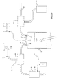
- an engine 10 has at least one combustion chamber 11.
- the engine 10 is of the reciprocating type, in which the combustion chamber 11 is a cylinder in which a piston 12 reciprocates.
- the invention is however applicable to other kinds of internal combustion engines such as for example rotary engines.
- the or each combustion chamber 11 has an inlet port 15 through which, in this example, primary combustion air is introduced, either by simple induction due to piston 12 movement, or with turbo assistance, and an exhaust outlet port 16. Both the inlet and outlet ports 15, 16 in this example are opened and closed by the operation of respective valves 17, 18 which typically are controlled to open and close in accordance with the engine cycle, e.g. by operating rods driven from a camshaft.
- the engine is a Diesel engine in which primary fuel for combustion is injected into the engine by an injector 19, and is ignited as a result of heat generated as air is compressed in the cylinder.
- ignition of the primary fuel may be achieved with spark assistance, and particularly in the case of a petrol spark ignition engine, primary fuel may be introduced into the combustion chamber 11 along with the primary air.
- the primary air may be introduced into the combustion chamber from an inlet manifold 20.
- the inlet ports 15 for each may be connected to the inlet manifold 20.
- Air is provided to the inlet manifold 20 from an air inlet 21, via air filters etc. as is well known in the art, and/or the air may be provided via a turbo device or otherwise.
- each exhaust outlet port 16 is connected to an exhaust manifold 23 of an exhaust system 24. Again in the case of a multi-combustion chamber 11 engine, the outlet ports 16 for each combustion chamber 11 may be connected to the exhaust manifold 23. Combustion gases pass, possibly via a catalytic converter 25, from the exhaust manifold, to atmosphere.
- the reformed fuel is then fed back into the combustion chamber 11 as hereinafter explained, and is subsequently burnt in the combustion chamber 11 along with primary fuel.
- a very small amount of the reformed fuel may pass through the combustion chamber 11 to the inlet port 15, and notwithstanding flow will be predominantly in an opposite direction, a very small amount of the reformed fuel may pass to the inlet manifold 20 for mixing with primary air.
- the primary air subsequently introduced into the combustion chamber 11 may contain a very small proportion of reformed fuel.
- FIG. 1 there is shown an apparatus 30 by means of which a secondary high calorific value vaporised fuel may be introduced into the inlet manifold 20, for introduction with the primary air into the combustion chamber.
- an aspirator 26 suitable for allowing secondary air to be introduced into the exhaust system 24 is shown.
- the aspirator 26 is tuned to maximise reformed fuel production from the secondary air and combustion products.
- the aspirator 26 includes a tube 32 which may be provided at one end 33, i.e. the lower end indicated in figure 2, with a male threaded boss, to enable the aspirator 26 conveniently to be attached to the outlet manifold 23, but the manifold 23 and aspirator 26 may otherwise be arranged to be connected.
- the tube is preferably made of a catalytic material, such as copper, which promotes reformed fuel production, and if desired, Cerium or another higher value but more efficient catalytic material, may be present in the exhaust system 24 further to promote the production of reformed fuel.
- a catalytic material such as copper, which promotes reformed fuel production, and if desired, Cerium or another higher value but more efficient catalytic material, may be present in the exhaust system 24 further to promote the production of reformed fuel.
- valve 35 At an opposite end 34 of the tube 32, at the top as shown in figure 2, there is provided a valve 35.
- the valve 35 includes a valve seat 36 accommodated in a housing 37 which is in the form of a mushroom shaped cap in this example.
- a valve member which in this case is a ball 40, is urged by a spring 41 into engagement with the valve seat 36 which is shaped to receive the ball 40, normally to close the valve and prevent air passing the valve 35 into the tube 32.
- the spring 41 is weak, and in the event that a low pressure or partial vacuum is experienced within the tube 32, the force of the spring 41 will be overcome and the ball 40 will be removed from the valve seat 36 so that air may be drawn in through the valve 35, and hence to tube 32 and the exhaust system 24.
- the aspirator 26 may be tuned to maximise reformed fuel production by setting the spring 41 pressure so that the valve 35 opens to maximise secondary air inflow at appropriate points in the engine cycle.
- the spring 41 and valve 35 construction generally are adapted so that the secondary air is introduced as strong pulses, with the valve opening and closing sharply. The pulses thus produced, mechanically act upon the combustion products and secondary air in the exhaust system 24 in the presence of the catalytic material, to reform fuel, typically hydrogen gas and methanol, which are introduced as described above into the combustion chamber 11.
- valve 35 construction may incorporate other than a ball shaped valve member 40, e.g. a disc shaped valve member, with the valve seat 36 being appropriately configured so that the aspirator 16 is tuned to maximise reformed fuel production.
- the tube 32 is shown to be bent, whereas in figure 2, the tube 32 is straight.
- the tube 32 may be bent as desired to fit within an engine compartment of a vehicle.
- the tube is about thirty centimetres in length, and typically the valve 35 is about 5 cm in length.
- the tube 32 diameter is typically about 0.79 cm.
- the operation of the aspirator 16 has been described with reference to particularly a single combustion chamber 11 engine 10, in which the low pressure or partial vacuum necessary to cause the valve 35 to open to allow secondary air to be drawn into the exhaust system 24, occurs when the piston 12 is at or substantially at the top of its stroke with the inlet 15 and exhaust ports 16 open.
- the valve 35 of the aspirator 26 may be arranged to open at a time which may not coincide with the piston 12 of any combustion chamber 11 being at the top of its stroke with the inlet 15 and exhaust ports 16 open.
- the pressure in the exhaust system 24 will tend to change according to a complex pattern. Nevertheless, the valve 35 of the aspirator 26 may be arranged to open against the force of spring 41 when a set low pressure or partial vacuum is experienced in the exhaust system 24.
- secondary air/reformed fuel may dwell in the exhaust system 24 but be introduced into the combustion chambers 11 when next a respective piston 12 is at the top of its stroke with the inlet 15 and exhaust ports 16 open.
- the low pressure or partial vacuum required for the introduction of secondary air into the exhaust system 24 may not coincide with the low pressure or partial vacuum experienced locally of the exhaust outlet ports 16 of the combustion chambers 11 necessary for the reformed fuel to be introduced into the combustion chambers 11.
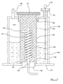
- FIG 3 there is shown an example of an apparatus 30 by means of which a secondary hydrocarbon based high calorific value vaporised fuel may be introduced into the combustion chamber 11 (or chamber) along with primary air for combustion.
- the apparatus 30 includes a reservoir 50 in which there is provided a hydrocarbon based liquid fuel, which conforms to British Standard 245.
- the container 50 may be filled with liquid fuel via a filler cap 51, and a dipstick 52 may be provided so that the liquid fuel level within the container 50 may readily be determined.
- the sub-assembly 59 includes a cylindrical housing 60 in which there is provided a coiled tube 61 which opens through the housing 60 at one end 62 thereof, into a space 65 above the level of the liquid fuel in the container 50, and at a lower end 64, opens through the housing 60 below the liquid fuel level.
- the sub-assembly 59 is removable form the container 50 by unscrewing from the mounting 58.
- the sub-assembly may in use, be also in threaded engagement with the container via a secondary mounting 68, and may include some means, such as a knurled ring 70, to facilitate removal and insertion of the sub-assembly 59 in the container 50.
- secondary fuel apparatus 50 instead of an electrical heater 55, or in addition thereto, means may be provided to enable the liquid fuel to be heated towards vaporisation, by another heat source, such as for example, hot exhaust gases produced by the engine 10.
- another heat source such as for example, hot exhaust gases produced by the engine 10.
- an existing engine 10 may be adapted to perform the invention by providing an aspirator 26 tuned to reformed fuel production, in the exhaust manifold 23, and if desired by providing a secondary fuel providing apparatus such as apparatus 50 described to work in conjunction therewith.
- the exhaust system 24 includes a catalytic converter 25, depending on whether this is a passive or active device, when adapting a engine for performance of the present invention, additional steps may need to be performed.
- the catalytic converter 25 includes a sensor 80 which provides an input to an engine management system 81, indicative of the concentration of un-burnt hydrocarbons and carbon monoxide in the exhaust gases
- the engine management system conventionally responds by setting the richness of the primary fuel/air mixture to a level where the catalytic converter 25 can operate most efficiently.
- the sensor 80 needs to be disabled and/or the engine management system 81 re-programmed to ensure that the richness of the primary fuel/air mixture is not unduly increased.
- the senor 80 may be used, or another sensor provided, to provide an input to the engine management system 81 in response to particular engine conditions arising to cause the secondary fuel apparatus 50 to operate or not to operate, e.g. by switching the electrical heating element 55 or other heating means on or off.
- reformed secondary fuel is introduced into the combination chamber via the exhaust port, for combustion with the primary fuel. Particularly where an excess of reformed fuel is produced, this may be collected and stored, and introduced into the combustion chamber later, e.g. along with the primary fuel rather than via the exhaust port.
- the invention is not exclusively applicable to internal combustion engines, but may be applied to other combustion apparatus such as a boiler or furnace having a combustion chamber preferably with an exhaust port through which reformed fuel may be introduced
Landscapes
- Engineering & Computer Science (AREA)
- Chemical & Material Sciences (AREA)
- Combustion & Propulsion (AREA)
- Mechanical Engineering (AREA)
- General Engineering & Computer Science (AREA)
- Chemical Kinetics & Catalysis (AREA)
- Oil, Petroleum & Natural Gas (AREA)
- Toxicology (AREA)
- Health & Medical Sciences (AREA)
- Exhaust Gas After Treatment (AREA)
- Regulation And Control Of Combustion (AREA)
- Valve Device For Special Equipments (AREA)
- Control Of Throttle Valves Provided In The Intake System Or In The Exhaust System (AREA)
- Incineration Of Waste (AREA)
- Gasification And Melting Of Waste (AREA)
- Solid-Fuel Combustion (AREA)
- Hydrogen, Water And Hydrids (AREA)
- Cylinder Crankcases Of Internal Combustion Engines (AREA)
Abstract
Description
Claims (15)
- A method of operating a combustion apparatus (10) which includes at least one combustion chamber (11) with an inlet port (15) for primary combustion air, means (19) to introduce into the combustion chamber primary fuel for combustion with the primary air, an exhaust port (16) for combustion products, and an exhaust system (24) for exhausting the combustion products to atmosphere, the method including introducing into the exhaust system (24) secondary air, mechanically acting upon the secondary air and products of combustion in the exhaust system (24) in the presence of a catalyst, to produce a reformed fuel, introducing the reformed fuel into the combustion chamber (11) for combustion with primary fuel and primary air.
- A method according to claim 1 characterised in that the reformed fuel is introduced in the combustion chamber (11) via the exhaust port (16).
- A method according to claim 1 or claim 2 characterised in that the combustion apparatus (10) is an internal combustion engine and secondary air is introduced into the exhaust system (24) via an exhaust aspirator (26) which draws air into the exhaust system (24) during low pressure or partial vacuum conditions occurring during the cycle of pressure changes which occur in the exhaust system (34) during normal operation of the engine (10).
- A method according to claim 3 characterised in that the exhaust aspirator (26) is tuned to draw air into the exhaust system (24) and mechanically to act upon the secondary air and products of combustion by means of pressure pulses, in a manner to optimise reformed fuel production.
- A method according to claim 3 or claim 4 characterised in that the aspirator (26) includes a valve (35) with a spring biased valve member (40), the force of the spring (41) acting to urge the valve member (40) into engagement with a valve seat (36) to close the valve (35), and the force of the spring (41) being overcome when sufficiently low pressure is developed in the exhaust system (24), to allow the secondary air to be drawn in through the valve (35) and the aspirator (26) being tuned by adjusting the spring (41) pressure so that the valve (35) responds to a desired low pressure or partial vacuum at an appropriate time during the engine cycle, and in a manner to produce strong pressure pulses in the exhaust system (24) adequate mechanically to act upon the combustion products and secondary air present in the exhaust system (24) in the presence of the catalyst, to produce reformed fuel.
- A method according to any one of the preceding claims characterised in that the reformed fuel includes one or both of methanol and hydrogen gas.
- A method according to any one of claims 3 to 5 characterised in that the catalyst is provided by materials from which the aspirator (26) is at least partly made.
- A method according to any one of the preceding claims characterised in that the combustion apparatus is a reciprocating piston engine (10) and the reformed fuel is introduced into the or each combustion chamber (11) of the engine (11) as a result of a partial vacuum being established at the exhaust port (16) at the end of an exhaust stroke of a piston thereof as the piston (12) commences its next induction stroke, before the exhaust port (16) is completely closed by an exhaust outlet valve (18) or the piston (12).
- A method according to any one of the preceding claims characterised in that the combustion apparatus (10) has a plurality of combustion chambers (11) each having an exhaust port (16), the exhaust ports each opening to an exhaust manifold (23), where the means for introducing secondary air into the exhaust system (24) is located.
- A method according to any one of the preceding claims characterised in that the method includes introducing reformed fuel obtained by mechanically acting upon drawn in secondary air and products of combustion in the exhaust system (24), into an inlet manifold (20) from where air is introduced into the combustion chamber (11) for combustion with the primary fuel.
- A method according to any one of the preceding claims characterised in that the method of the invention includes introducing into the combustion chamber (11) of the apparatus (10), a vaporised secondary hydrocarbon based high calorific value fuel, obtained by heating a mineral oil electrically and/or by heat exchange with hot exhaust gases produced by the apparatus (10) to vaporise the oil.
- A method according to claim 11 characterised in that the combustion apparatus 10 is a spark ignition engine and the primary fuel is induced and/or injected into the combustion chamber (11) together with the vaporised secondary hydrocarbon based high calorific value fuel.
- A method according to claim 11 characterised in that the combustion apparatus (10) is an engine of the kind in which the primary fuel is introduced by injection, and vaporised secondary hydrocarbon based high calorific value fuel is introduced with the induced air.
- A method of adapting a combustion apparatus (10) having at least one combustion chamber (11), for operation in accordance with any one of the preceding claims, the method including providing the combustion apparatus (10) with means to introduce into the exhaust system (24) secondary air, providing means (26) mechanically to act upon the secondary air and products of combustion in the exhaust system (24) in the presence of a catalyst, to produce a reformed fuel, and means to introduce the secondary fuel into the combustion chamber (11) of the apparatus (10) via the exhaust port (16) for combustion with primary fuel and primary air.
- A method according to claim 14 characterised in that the combustion apparatus (10) is an engine of a vehicle, the vehicle engine (10) of which is to be adapted includes a catalytic converter (25) already and an engine management system (81) thereof is provided with an input from a sensor (80) associated with the catalytic converter (25) which affects engine control, the method including disabling the sensor (80) of the catalytic converter or re-programming the engine management system (81).
Applications Claiming Priority (3)
| Application Number | Priority Date | Filing Date | Title |
|---|---|---|---|
| GB0026397 | 2000-10-28 | ||
| GB0026397A GB2368371B (en) | 2000-10-28 | 2000-10-28 | Method of operating an engine |
| PCT/GB2001/004755 WO2002035078A1 (en) | 2000-10-28 | 2001-10-26 | Method of operating a combustion apparatus |
Publications (2)
| Publication Number | Publication Date |
|---|---|
| EP1328717A1 EP1328717A1 (en) | 2003-07-23 |
| EP1328717B1 true EP1328717B1 (en) | 2004-08-04 |
Family
ID=9902129
Family Applications (1)
| Application Number | Title | Priority Date | Filing Date |
|---|---|---|---|
| EP01976531A Expired - Lifetime EP1328717B1 (en) | 2000-10-28 | 2001-10-26 | Method of operating a combustion apparatus |
Country Status (11)
| Country | Link |
|---|---|
| US (1) | US6769244B2 (en) |
| EP (1) | EP1328717B1 (en) |
| JP (1) | JP2004512456A (en) |
| KR (1) | KR20020084083A (en) |
| AT (1) | ATE272790T1 (en) |
| AU (1) | AU2001295799A1 (en) |
| DE (1) | DE60104712T2 (en) |
| ES (1) | ES2227289T3 (en) |
| GB (1) | GB2368371B (en) |
| NO (1) | NO20023165L (en) |
| WO (1) | WO2002035078A1 (en) |
Families Citing this family (19)
| Publication number | Priority date | Publication date | Assignee | Title |
|---|---|---|---|---|
| RU2273750C1 (en) * | 2004-12-06 | 2006-04-10 | ФГОУ ВПО "Пензенская государственная сельскохозяйственная академия" | System for automatic control of delivery of activator into diesel engine |
| US8429896B2 (en) | 2006-04-18 | 2013-04-30 | Kohler Co. | Engine exhaust systems with secondary air injection systems |
| RU2330173C2 (en) * | 2006-07-31 | 2008-07-27 | ФГОУ ВПО "Пензенская государственная сельскохозяйственная академия" | Air charge upgrading device |
| WO2009102500A2 (en) * | 2008-02-15 | 2009-08-20 | Cummins Inc. | System and method for on-board waste heat recovery |
| RU2392481C1 (en) * | 2008-12-24 | 2010-06-20 | ФГОУ ВПО "Пензенская государственная сельскохозяйственная академия" | Air diesel charge enrichment device |
| CN102066737A (en) * | 2009-06-18 | 2011-05-18 | 阿罗诺克斯技术公司 | Apparatus for reforming air in an internal combustion engine |
| RU2453716C2 (en) * | 2010-03-09 | 2012-06-20 | ФГОУ ВПО "Пензенская государственная сельскохозяйственная академия" | System for automatic control over activator feed into diesel engine intake pipeline |
| RU2451807C2 (en) * | 2010-03-22 | 2012-05-27 | Федеральное государственное образовательное учреждение высшего профессионального образования "Пензенская государственная сельскохозяйственная академия" | Device to vary amount of activating air mix in diesel engine inlet manifold |
| US8863701B2 (en) | 2011-10-24 | 2014-10-21 | Saudi Arabian Oil Company | Emission reduction from mobile sources by on-board carbon dioxide conversion to fuel |
| CN103183316B (en) * | 2011-12-29 | 2015-03-11 | 火传利能科技股份有限公司 | Methanol Reformer Started Using Engine Waste Heat |
| US9175783B2 (en) | 2012-11-16 | 2015-11-03 | Ford Global Technologies, Llc | Vacuum-actuated wastegate |
| US9322289B2 (en) | 2012-11-16 | 2016-04-26 | Ford Global Technologies, Llc | Vacuum-actuated wastegate |
| US9074523B2 (en) | 2012-11-16 | 2015-07-07 | Ford Global Technologies, Llc | Vacuum-actuated wastegate |
| RU2515586C1 (en) * | 2012-12-03 | 2014-05-10 | Федеральное государственное бюджетное образовательное учреждение высшего профессионального образования "Пензенская государственная сельскохозяйственная академия" | Device for diesel supercharging by air enrichment |
| RU2518711C1 (en) * | 2012-12-11 | 2014-06-10 | Федеральное государственное бюджетное образовательное учреждение высшего профессионального образования "Пензенская государственная сельскохозяйственная академия" | System for control over activator injection in diesel intake pipeline |
| US9238598B2 (en) | 2013-01-04 | 2016-01-19 | Saudi Arabian Oil Company | Carbon dioxide conversion to hydrocarbon fuel via syngas production cell harnessed from solar radiation |
| GB2547948B (en) * | 2016-03-04 | 2021-06-09 | Clearairtech Ltd | Method of operating an internal combustion engine, exhaust aspirator for an internal combustion engine, and an internal combustion engine |
| JP6789907B2 (en) * | 2017-09-21 | 2020-11-25 | ヤンマーパワーテクノロジー株式会社 | Internal combustion engine |
| CN116161619A (en) * | 2023-03-10 | 2023-05-26 | 中车资阳机车有限公司 | Online hydrogen production system for methanol of hydrogen diesel locomotive |
Family Cites Families (12)
| Publication number | Priority date | Publication date | Assignee | Title |
|---|---|---|---|---|
| US3918412A (en) | 1970-04-30 | 1975-11-11 | Lindstroem Ab Olle | Fuel treatment for combustion engines |
| DE2103008C3 (en) * | 1971-01-22 | 1978-11-02 | Siemens Ag, 1000 Berlin Und 8000 Muenchen | Device for generating a gaseous fuel |
| US3913322A (en) * | 1973-08-29 | 1975-10-21 | Kinematics Limited | Internal combustion engines |
| ATE39544T1 (en) * | 1980-06-06 | 1989-01-15 | Pulse Air Res Ltd | DEVICE FOR AIR SUPPLY IN THE EXHAUST MANIFOLD OF AN ENGINE. |
| GB2161212A (en) | 1984-04-07 | 1986-01-08 | Jaguar Cars | Cracking fuel and supplying to an internal combustion engine |
| US6155212A (en) * | 1989-06-12 | 2000-12-05 | Mcalister; Roy E. | Method and apparatus for operation of combustion engines |
| JPH05106430A (en) * | 1991-10-16 | 1993-04-27 | Toyota Central Res & Dev Lab Inc | Nitrogen oxide reduction device for internal combustion engine |
| GB2290348A (en) | 1994-02-11 | 1995-12-20 | Avonbray Ltd | Engine supplied with vaporised secondary fuel |
| SE506971C2 (en) * | 1996-07-22 | 1998-03-09 | Volvo Ab | Method and apparatus for exhaust gas purification by means of a canister |
| US5943859A (en) * | 1997-09-18 | 1999-08-31 | Isuzu Ceramics Research Institute Co., Ltd. | Natural gas reforming apparatus, oxygen eliminating apparatus provided in the same apparatus, and natural gas reforming apparatus-carrying gas engine |
| GB2349419A (en) * | 1999-04-30 | 2000-11-01 | Ford Global Tech Inc | An internal combustion engine with internal egr to thermally condition fuel |
| EP1124053A3 (en) * | 2000-02-09 | 2003-01-08 | Nissan Motor Co., Ltd. | Fuel vapor treatment system |
-
2000
- 2000-10-28 GB GB0026397A patent/GB2368371B/en not_active Expired - Fee Related
-
2001
- 2001-10-26 JP JP2002538034A patent/JP2004512456A/en active Pending
- 2001-10-26 ES ES01976531T patent/ES2227289T3/en not_active Expired - Lifetime
- 2001-10-26 EP EP01976531A patent/EP1328717B1/en not_active Expired - Lifetime
- 2001-10-26 AU AU2001295799A patent/AU2001295799A1/en not_active Abandoned
- 2001-10-26 AT AT01976531T patent/ATE272790T1/en active
- 2001-10-26 WO PCT/GB2001/004755 patent/WO2002035078A1/en not_active Ceased
- 2001-10-26 DE DE60104712T patent/DE60104712T2/en not_active Expired - Lifetime
- 2001-10-26 US US10/169,271 patent/US6769244B2/en not_active Expired - Fee Related
- 2001-10-26 KR KR1020027008498A patent/KR20020084083A/en not_active Withdrawn
-
2002
- 2002-06-28 NO NO20023165A patent/NO20023165L/en not_active Application Discontinuation
Also Published As
| Publication number | Publication date |
|---|---|
| US6769244B2 (en) | 2004-08-03 |
| ATE272790T1 (en) | 2004-08-15 |
| NO20023165L (en) | 2002-08-27 |
| KR20020084083A (en) | 2002-11-04 |
| DE60104712T2 (en) | 2005-09-08 |
| GB2368371B (en) | 2004-05-12 |
| ES2227289T3 (en) | 2005-04-01 |
| US20020189245A1 (en) | 2002-12-19 |
| WO2002035078A1 (en) | 2002-05-02 |
| NO20023165D0 (en) | 2002-06-28 |
| GB0026397D0 (en) | 2000-12-13 |
| EP1328717A1 (en) | 2003-07-23 |
| AU2001295799A1 (en) | 2002-05-06 |
| JP2004512456A (en) | 2004-04-22 |
| GB2368371A (en) | 2002-05-01 |
| DE60104712D1 (en) | 2004-09-09 |
Similar Documents
| Publication | Publication Date | Title |
|---|---|---|
| US6769244B2 (en) | Method of operating a combustion apparatus | |
| EP0783624B1 (en) | Charge conditioning system for enabling cold starting and running of spark-ignited, diesel fueled piston engines | |
| CN114183262B (en) | Direct-injection hydrogen internal combustion engine in jet ignition cylinder of precombustion chamber and control method | |
| US6062186A (en) | Method of starting an engine | |
| EP0426320B1 (en) | Re-combustion control means for alcohol engine | |
| WO1984000994A1 (en) | Internal combustion engine for diverse fuels | |
| CN103670753A (en) | Spark-ignition direct injection engine | |
| US20190170077A1 (en) | Combustion control method and combustion control system with variable excess air coefficient for gasoline engine | |
| RU2000130804A (en) | METHOD OF OPERATION OF THE INTERNAL COMBUSTION ENGINE WITH COMPRESSION Ignition | |
| CN114109627B (en) | In-cylinder direct-injection hydrogen internal combustion engine based on diesel engine and combustion control method | |
| JPH10153149A (en) | Fuel heating system for engines using heavy oil as fuel | |
| JP5002034B2 (en) | Fuel control device for internal combustion engine | |
| GB2394511A (en) | Internal combustion engine with direct water injection into cylinder | |
| JP2889915B2 (en) | Water evaporator | |
| US4442809A (en) | Combustion chamber of an internal combustion engine with an accumulation chamber | |
| CN203547937U (en) | Alcohol and gasoline double-fuel injection and control system for gasoline internal combustion engine | |
| JPH06193480A (en) | Hydrogen engine fuel supply system | |
| JP2025125467A (en) | Fuel reforming system for engine-equipped vehicles | |
| CN101644208B (en) | Engine energy-saving and emission-reducing system coordinated by heat pipe and cold pipe and working method thereof | |
| US20060225672A1 (en) | Vapor injection system for an internal combustion engine | |
| KR100568994B1 (en) | Energy increaser of heat engine | |
| KR200244547Y1 (en) | Liquid fuel heating device of gasoline engine | |
| KR930003540B1 (en) | Combustion apparatus of internal combustion engine using high temperature steam | |
| RU1784067C (en) | Internal combustion engine | |
| EP2042722A2 (en) | Method for increasing the efficiency of an internal combustion engine, supply system for an internal combustion engine implementing said method and perfected internal combustion engine |
Legal Events
| Date | Code | Title | Description |
|---|---|---|---|
| PUAI | Public reference made under article 153(3) epc to a published international application that has entered the european phase |
Free format text: ORIGINAL CODE: 0009012 |
|
| 17P | Request for examination filed |
Effective date: 20020627 |
|
| AK | Designated contracting states |
Designated state(s): AT BE CH CY DE DK ES FI FR GB GR IE IT LI LU MC NL PT SE TR |
|
| AX | Request for extension of the european patent |
Extension state: AL LT LV MK RO SI |
|
| GRAP | Despatch of communication of intention to grant a patent |
Free format text: ORIGINAL CODE: EPIDOSNIGR1 |
|
| RAP1 | Party data changed (applicant data changed or rights of an application transferred) |
Owner name: CLEARAIR TECHNOLOGY LIMITED |
|
| GRAS | Grant fee paid |
Free format text: ORIGINAL CODE: EPIDOSNIGR3 |
|
| GRAA | (expected) grant |
Free format text: ORIGINAL CODE: 0009210 |
|
| AK | Designated contracting states |
Kind code of ref document: B1 Designated state(s): AT BE CH CY DE DK ES FI FR GB GR IE IT LI LU MC NL PT SE TR |
|
| PG25 | Lapsed in a contracting state [announced via postgrant information from national office to epo] |
Ref country code: FI Free format text: LAPSE BECAUSE OF FAILURE TO SUBMIT A TRANSLATION OF THE DESCRIPTION OR TO PAY THE FEE WITHIN THE PRESCRIBED TIME-LIMIT Effective date: 20040804 Ref country code: CH Free format text: LAPSE BECAUSE OF FAILURE TO SUBMIT A TRANSLATION OF THE DESCRIPTION OR TO PAY THE FEE WITHIN THE PRESCRIBED TIME-LIMIT Effective date: 20040804 Ref country code: LI Free format text: LAPSE BECAUSE OF FAILURE TO SUBMIT A TRANSLATION OF THE DESCRIPTION OR TO PAY THE FEE WITHIN THE PRESCRIBED TIME-LIMIT Effective date: 20040804 Ref country code: CY Free format text: LAPSE BECAUSE OF FAILURE TO SUBMIT A TRANSLATION OF THE DESCRIPTION OR TO PAY THE FEE WITHIN THE PRESCRIBED TIME-LIMIT Effective date: 20040804 Ref country code: NL Free format text: LAPSE BECAUSE OF FAILURE TO SUBMIT A TRANSLATION OF THE DESCRIPTION OR TO PAY THE FEE WITHIN THE PRESCRIBED TIME-LIMIT Effective date: 20040804 |
|
| REG | Reference to a national code |
Ref country code: GB Ref legal event code: FG4D |
|
| REG | Reference to a national code |
Ref country code: CH Ref legal event code: EP |
|
| REG | Reference to a national code |
Ref country code: IE Ref legal event code: FG4D |
|
| REF | Corresponds to: |
Ref document number: 60104712 Country of ref document: DE Date of ref document: 20040909 Kind code of ref document: P |
|
| RBV | Designated contracting states (corrected) |
Designated state(s): AT BE CH CY DE DK ES FI FR GR IE IT LI LU MC NL PT SE TR |
|
| PG25 | Lapsed in a contracting state [announced via postgrant information from national office to epo] |
Ref country code: LU Free format text: LAPSE BECAUSE OF NON-PAYMENT OF DUE FEES Effective date: 20041026 |
|
| PG25 | Lapsed in a contracting state [announced via postgrant information from national office to epo] |
Ref country code: MC Free format text: LAPSE BECAUSE OF NON-PAYMENT OF DUE FEES Effective date: 20041031 |
|
| PG25 | Lapsed in a contracting state [announced via postgrant information from national office to epo] |
Ref country code: DK Free format text: LAPSE BECAUSE OF FAILURE TO SUBMIT A TRANSLATION OF THE DESCRIPTION OR TO PAY THE FEE WITHIN THE PRESCRIBED TIME-LIMIT Effective date: 20041104 |
|
| REG | Reference to a national code |
Ref country code: SE Ref legal event code: TRGR |
|
| REG | Reference to a national code |
Ref country code: GB Ref legal event code: ERR Free format text: NOTIFICATION HAS BEEN RECEIVED FROM THE EUROPEAN PATENT OFFICE THAT THIS DESIGNATION HAS BEEN WITHDRAWN. THIS CORRECTION WILL BE PUBLISHED IN EUROPEAN PATENT BULLETIN NO. 04/39 OF 20040922. |
|
| REG | Reference to a national code |
Ref country code: GR Ref legal event code: EP Ref document number: 20040403793 Country of ref document: GR |
|
| NLV1 | Nl: lapsed or annulled due to failure to fulfill the requirements of art. 29p and 29m of the patents act | ||
| LTIE | Lt: invalidation of european patent or patent extension |
Effective date: 20040804 |
|
| REG | Reference to a national code |
Ref country code: CH Ref legal event code: PL |
|
| REG | Reference to a national code |
Ref country code: ES Ref legal event code: FG2A Ref document number: 2227289 Country of ref document: ES Kind code of ref document: T3 |
|
| PLBE | No opposition filed within time limit |
Free format text: ORIGINAL CODE: 0009261 |
|
| STAA | Information on the status of an ep patent application or granted ep patent |
Free format text: STATUS: NO OPPOSITION FILED WITHIN TIME LIMIT |
|
| ET | Fr: translation filed | ||
| 26N | No opposition filed |
Effective date: 20050506 |
|
| PG25 | Lapsed in a contracting state [announced via postgrant information from national office to epo] |
Ref country code: PT Free format text: LAPSE BECAUSE OF NON-PAYMENT OF DUE FEES Effective date: 20050104 |
|
| PGFP | Annual fee paid to national office [announced via postgrant information from national office to epo] |
Ref country code: TR Payment date: 20110422 Year of fee payment: 10 |
|
| PGFP | Annual fee paid to national office [announced via postgrant information from national office to epo] |
Ref country code: DE Payment date: 20120430 Year of fee payment: 11 Ref country code: BE Payment date: 20120406 Year of fee payment: 11 Ref country code: IE Payment date: 20120411 Year of fee payment: 11 |
|
| PGFP | Annual fee paid to national office [announced via postgrant information from national office to epo] |
Ref country code: FR Payment date: 20120530 Year of fee payment: 11 Ref country code: GR Payment date: 20120410 Year of fee payment: 11 Ref country code: SE Payment date: 20120405 Year of fee payment: 11 |
|
| PGFP | Annual fee paid to national office [announced via postgrant information from national office to epo] |
Ref country code: IT Payment date: 20120419 Year of fee payment: 11 |
|
| PGFP | Annual fee paid to national office [announced via postgrant information from national office to epo] |
Ref country code: ES Payment date: 20120524 Year of fee payment: 11 |
|
| PGFP | Annual fee paid to national office [announced via postgrant information from national office to epo] |
Ref country code: AT Payment date: 20120406 Year of fee payment: 11 |
|
| BERE | Be: lapsed |
Owner name: *CLEARAIR TECHNOLOGY LTD Effective date: 20121031 |
|
| REG | Reference to a national code |
Ref country code: AT Ref legal event code: MM01 Ref document number: 272790 Country of ref document: AT Kind code of ref document: T Effective date: 20121026 |
|
| REG | Reference to a national code |
Ref country code: GR Ref legal event code: ML Ref document number: 20040403793 Country of ref document: GR Effective date: 20130508 |
|
| REG | Reference to a national code |
Ref country code: IE Ref legal event code: MM4A |
|
| REG | Reference to a national code |
Ref country code: FR Ref legal event code: ST Effective date: 20130628 |
|
| PG25 | Lapsed in a contracting state [announced via postgrant information from national office to epo] |
Ref country code: SE Free format text: LAPSE BECAUSE OF NON-PAYMENT OF DUE FEES Effective date: 20121027 Ref country code: BE Free format text: LAPSE BECAUSE OF NON-PAYMENT OF DUE FEES Effective date: 20121031 Ref country code: AT Free format text: LAPSE BECAUSE OF NON-PAYMENT OF DUE FEES Effective date: 20121026 Ref country code: DE Free format text: LAPSE BECAUSE OF NON-PAYMENT OF DUE FEES Effective date: 20130501 Ref country code: IE Free format text: LAPSE BECAUSE OF NON-PAYMENT OF DUE FEES Effective date: 20121026 |
|
| REG | Reference to a national code |
Ref country code: DE Ref legal event code: R119 Ref document number: 60104712 Country of ref document: DE Effective date: 20130501 |
|
| PG25 | Lapsed in a contracting state [announced via postgrant information from national office to epo] |
Ref country code: IT Free format text: LAPSE BECAUSE OF NON-PAYMENT OF DUE FEES Effective date: 20121026 Ref country code: GR Free format text: LAPSE BECAUSE OF NON-PAYMENT OF DUE FEES Effective date: 20130508 Ref country code: FR Free format text: LAPSE BECAUSE OF NON-PAYMENT OF DUE FEES Effective date: 20121031 |
|
| PG25 | Lapsed in a contracting state [announced via postgrant information from national office to epo] |
Ref country code: TR Free format text: LAPSE BECAUSE OF NON-PAYMENT OF DUE FEES Effective date: 20121025 |
|
| REG | Reference to a national code |
Ref country code: ES Ref legal event code: FD2A Effective date: 20140207 |
|
| PG25 | Lapsed in a contracting state [announced via postgrant information from national office to epo] |
Ref country code: ES Free format text: LAPSE BECAUSE OF NON-PAYMENT OF DUE FEES Effective date: 20121027 |