EP1328007A1 - Dielectric barrier discharge lamp with starting aid. - Google Patents
Dielectric barrier discharge lamp with starting aid. Download PDFInfo
- Publication number
- EP1328007A1 EP1328007A1 EP01129856A EP01129856A EP1328007A1 EP 1328007 A1 EP1328007 A1 EP 1328007A1 EP 01129856 A EP01129856 A EP 01129856A EP 01129856 A EP01129856 A EP 01129856A EP 1328007 A1 EP1328007 A1 EP 1328007A1
- Authority
- EP
- European Patent Office
- Prior art keywords
- dielectric barrier
- discharge lamp
- barrier discharge
- lamp according
- exhaust tube
- Prior art date
- Legal status (The legal status is an assumption and is not a legal conclusion. Google has not performed a legal analysis and makes no representation as to the accuracy of the status listed.)
- Withdrawn
Links
- 230000004888 barrier function Effects 0.000 title claims abstract description 52
- 239000000463 material Substances 0.000 claims description 7
- PNEYBMLMFCGWSK-UHFFFAOYSA-N aluminium oxide Inorganic materials [O-2].[O-2].[O-2].[Al+3].[Al+3] PNEYBMLMFCGWSK-UHFFFAOYSA-N 0.000 claims description 6
- 229910052710 silicon Inorganic materials 0.000 claims description 6
- 239000010703 silicon Substances 0.000 claims description 6
- 239000011810 insulating material Substances 0.000 claims description 4
- 229910052593 corundum Inorganic materials 0.000 claims description 3
- 229910001845 yogo sapphire Inorganic materials 0.000 claims description 3
- 239000000203 mixture Substances 0.000 claims description 2
- 239000003623 enhancer Substances 0.000 description 8
- XUIMIQQOPSSXEZ-UHFFFAOYSA-N Silicon Chemical compound [Si] XUIMIQQOPSSXEZ-UHFFFAOYSA-N 0.000 description 5
- 230000005684 electric field Effects 0.000 description 5
- 239000011521 glass Substances 0.000 description 3
- 239000011248 coating agent Substances 0.000 description 2
- 238000000576 coating method Methods 0.000 description 2
- 229910052751 metal Inorganic materials 0.000 description 2
- 239000002184 metal Substances 0.000 description 2
- 230000015556 catabolic process Effects 0.000 description 1
- 230000001419 dependent effect Effects 0.000 description 1
- 150000002739 metals Chemical class 0.000 description 1
- BPUBBGLMJRNUCC-UHFFFAOYSA-N oxygen(2-);tantalum(5+) Chemical compound [O-2].[O-2].[O-2].[O-2].[O-2].[Ta+5].[Ta+5] BPUBBGLMJRNUCC-UHFFFAOYSA-N 0.000 description 1
- 229910001936 tantalum oxide Inorganic materials 0.000 description 1
- 229910052724 xenon Inorganic materials 0.000 description 1
- FHNFHKCVQCLJFQ-UHFFFAOYSA-N xenon atom Chemical compound [Xe] FHNFHKCVQCLJFQ-UHFFFAOYSA-N 0.000 description 1
Images




Classifications
-
- H—ELECTRICITY
- H01—ELECTRIC ELEMENTS
- H01J—ELECTRIC DISCHARGE TUBES OR DISCHARGE LAMPS
- H01J61/00—Gas-discharge or vapour-discharge lamps
- H01J61/02—Details
- H01J61/04—Electrodes; Screens; Shields
-
- H—ELECTRICITY
- H01—ELECTRIC ELEMENTS
- H01J—ELECTRIC DISCHARGE TUBES OR DISCHARGE LAMPS
- H01J61/00—Gas-discharge or vapour-discharge lamps
- H01J61/02—Details
- H01J61/54—Igniting arrangements, e.g. promoting ionisation for starting
- H01J61/545—Igniting arrangements, e.g. promoting ionisation for starting using an auxiliary electrode inside the vessel
-
- H—ELECTRICITY
- H01—ELECTRIC ELEMENTS
- H01J—ELECTRIC DISCHARGE TUBES OR DISCHARGE LAMPS
- H01J61/00—Gas-discharge or vapour-discharge lamps
- H01J61/02—Details
- H01J61/54—Igniting arrangements, e.g. promoting ionisation for starting
- H01J61/547—Igniting arrangements, e.g. promoting ionisation for starting using an auxiliary electrode outside the vessel
-
- H—ELECTRICITY
- H01—ELECTRIC ELEMENTS
- H01J—ELECTRIC DISCHARGE TUBES OR DISCHARGE LAMPS
- H01J65/00—Lamps without any electrode inside the vessel; Lamps with at least one main electrode outside the vessel
- H01J65/04—Lamps in which a gas filling is excited to luminesce by an external electromagnetic field or by external corpuscular radiation, e.g. for indicating plasma display panels
- H01J65/042—Lamps in which a gas filling is excited to luminesce by an external electromagnetic field or by external corpuscular radiation, e.g. for indicating plasma display panels by an external electromagnetic field
- H01J65/046—Lamps in which a gas filling is excited to luminesce by an external electromagnetic field or by external corpuscular radiation, e.g. for indicating plasma display panels by an external electromagnetic field the field being produced by using capacitive means around the vessel
Definitions
- the invention relates to dielectric barrier discharge lamps according to the preamble of claim 1.
- dielectric barrier discharge lamps also known as dielectrically impeded or silent discharge lamps
- dielectrically impeded or silent discharge lamps starting of conventional discharge lamps. This is because no metallic electrodes reach into the discharge space which could be used to emit initial electrons by thermal or field emission.
- dielectric barrier discharge lamps a metallic electrode is covered by a dielectric barrier which prevents electrons from the electrodes to reach the discharge space.
- the electrodes are for example provided on the inner surface of the discharge vessel - a dielectric layer covers the electrodes of distinguished polarity (unilaterally dielectrically impeded discharge) or all electrodes, i.e. of both polarities (bilaterally dielectrically impeded discharge).
- a dielectric layer covers the electrodes of distinguished polarity (unilaterally dielectrically impeded discharge) or all electrodes, i.e. of both polarities (bilaterally dielectrically impeded discharge).
- the walls of the discharge vessel act as the dielectric barrier.
- US 5,432,398 discloses a dielectric barrier discharge lamp with improved ignition by providing means for local field distortion in the discharge space.
- the means is for example a disturbing body made of aluminium oxide or tantalum oxide.
- the dielectric barrier discharge lamp according to the invention comprises a discharge vessel having at least one tipped off exhaust tube, the discharge vessel (and hence the exhaust tube) being filled with a filling gas, and main electrodes characterised by at least one means for igniting an auxiliary discharge inside said exhaust tube.
- This auxiliary discharge facilitates the ignition of the main discharge within the interior of the discharge vessel.
- the main discharge is generated between the main electrodes.
- the means for igniting is for instance a coil wound around the exhaust tube or at least one auxiliary electrode provided along the exhaust tube.
- the purpose of the coil or the at least one auxiliary electrode is to facilitate an auxiliary discharge originating within the interior of the exhaust tube.
- the means for igniting is preferably in electrical contact with a main electrode. That way, a separate power supply for the means for igniting the auxiliary discharge is not necessary.
- the coil or the at least one auxiliary electrode is preferably mounted on the exhaust tube in close proximity to the discharge vessel, i.e. away from the tipped-off portion of the exhaust tube.
- auxiliary electrode In case of a single auxiliary electrode the (dielectrically impeded) auxiliary discharge is generated between the auxiliary electrode and the main electrode of opposite polarity. In case of a pair of auxiliary electrode the (dielectrically impeded) auxiliary discharge is generated between both auxiliary electrodes.
- the latter is assumed to be the preferred variant, because of the higher electrical field strength due to the shorter distance between both auxiliary electrodes compared to the longer distance between an auxiliary electrode and a main electrode.
- auxiliary electrode is belt-shaped and coaxially aligned with the exhaust tube.
- the inner surface of the exhaust tube can be covered with a material having a high secondary electron emission coefficient, e.g. MgO or Al 2 O 3 or a mixture thereof.
- the ignition of the dielectric barrier discharge lamp can be improved by providing a metallic structure inside the exhaust tube.
- the metallic structure enhances the strength of the electrical field inside the exhaust tube (metallic field enhancer).
- metallic components in the exhaust tube increase the probability for field emission of electrons due to their low work function in comparison to glass or other non conductive oxides.
- the metallic structure is for example U-, ring- or coil-shaped. Metals with low work function are preferred for the metallic structure.
- the metallic structure can be covered with a material lowering the work function.
- the auxiliary electrodes are preferably covered at least in part by an insulating material, e.g. silicon or silicon gel.
- the dielectric barrier discharge lamp essentially comprises a tubular discharge vessel 1, two strip-shaped internal (main) electrodes (not shown), two strip-shaped auxiliary electrodes 2 and two supply leads 3. The main electrodes are in electrical contact with the supply leads (not shown).
- Dielectric barrier 4 covering each electrode is shown in FIG. 1a.
- the general concept of this kind of dielectric barrier discharge lamp with internal (main) electrodes is described in detail in US 6,097,155, particularly in the description of FIGS. 1a, 1b and 2 therein.
- the discharge vessel 1 is sealed in a gas-tight fashion at its first end by means of a flare mount with a tipped-off exhaust tube 5 and at its second end by a dome (not shown) formed from the vessel.
- the discharge vessel 1 is filled with Xenon at a filling pressure of 15 kPa.
- Each auxiliary electrode 2 is U-shaped. A first shank of each U-shaped auxiliary electrode 2 is in electrical contact with one supply lead 3. The second shank of each U-shaped auxiliary electrode 2 is in contact with the outer surface of the exhaust tube 5.
- Each auxiliary electrode 2 is coaxial aligned with the exhaust tube 5 (see FIG 1b). During the ignition phase a high voltage is applied to the supply leads 3.
- the strength of the electrical field generated by the auxiliary electrodes 2 within the exhaust tube 5 is higher than within the discharge vessel, because the of the smaller inner diameter of the exhaust tube 5 in comparison to the inner diameter of the discharge vessel 1. Therefore, ignition of an auxiliary dielectric barrier discharge between the auxiliary electrodes 2 and within the interior of the exhaust tube 5 is facilitated. Eventually, the auxiliary discharge initiates the ignition of the main discharge.
- the space between the auxiliary electrodes 2 is insulated with silicon 6.
- arcing can be avoided by applying a silicon gel along the glass surface between the electrodes (not shown). Both auxiliary electrodes 2, the silicon 6, and the high voltage supply leads 3 are integrated to a single structure which is placed onto the lamp and soldered to the main electrodes of the lamp.
- the inner surface of the flare can also be coated with materials with high secondary electron emission capability such as Al 2 O 3 or MgO.
- FIGS. 2a and 2b show a variation of the above lamp with a coating 7 made of MgO on the inner surface of the exhaust tube 5. Since MgO is a good secondary electron emitter, the coating 7 enhances the electron density.
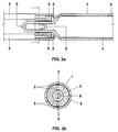
- FIGS. 3a, 3b, 4a, 4b and 5a, 5b show further variations of the dielectric barrier discharge lamp as shown in FIGS. 1a, 1b. Further enhancement of starting is achieved by placing metal structures in the interior of the exhaust tube 5, which enhance the strength of the electrical field inside the exhaust tube 5 (metallic field enhancer). In addition, metallic components in the exhaust tube 5 increase the probability for field emission of electrons due to their low work function in comparison to glass or other non conductive oxides.
- FIGS. 3a, 3b show a dielectric barrier discharge lamp with a U-shaped field enhancer 8.
- FIGS. 4a, 4b show a dielectric barrier discharge lamp with a ring-shaped field enhancer 9.
- FIGS. 5a, 5b show a dielectric barrier discharge lamp with a coil-shaped field enhancer 10.
Landscapes
- Physics & Mathematics (AREA)
- Electromagnetism (AREA)
- Engineering & Computer Science (AREA)
- Plasma & Fusion (AREA)
- Discharge Lamps And Accessories Thereof (AREA)
- Vessels And Coating Films For Discharge Lamps (AREA)
Abstract
In order to improve the starting of a dielectric barrier discharge lamp it is proposed to provide means for iquiting and auxiliary discharge inside the exhaust tube (5) of the lamp.
Description
- The invention relates to dielectric barrier discharge lamps according to the preamble of
claim 1. - Starting of dielectric barrier discharge lamps (also known as dielectrically impeded or silent discharge lamps) is more difficult than starting of conventional discharge lamps such as low pressure fluorescent lamps. This is because no metallic electrodes reach into the discharge space which could be used to emit initial electrons by thermal or field emission. In dielectric barrier discharge lamps a metallic electrode is covered by a dielectric barrier which prevents electrons from the electrodes to reach the discharge space.
- In case of so-called internal electrodes - the electrodes are for example provided on the inner surface of the discharge vessel - a dielectric layer covers the electrodes of distinguished polarity (unilaterally dielectrically impeded discharge) or all electrodes, i.e. of both polarities (bilaterally dielectrically impeded discharge). In case of so-called external electrodes the walls of the discharge vessel act as the dielectric barrier. For more details see US 6,097,155.
- In any case, in order to start the lamp, initial charges which are within the discharge volume have to be multiplied by an electrical field in a very effective way in order to achieve an electrical breakdown (ignition) of the gas. In this regard the initial ignition of dielectric barrier discharge lamps or ignition after relatively long pauses or ignition in dark places are even more critical.
- US 5,432,398 discloses a dielectric barrier discharge lamp with improved ignition by providing means for local field distortion in the discharge space. The means is for example a disturbing body made of aluminium oxide or tantalum oxide.
- It is an object of the invention to provide another means for improving the starting of a dielectric barrier discharge lamp.
- The object is achieved by a dielectric barrier discharge lamp with the features according to
claim 1. - Additional features of preferred embodiments are specified in the dependent claims.
- The dielectric barrier discharge lamp according to the invention comprises a discharge vessel having at least one tipped off exhaust tube, the discharge vessel (and hence the exhaust tube) being filled with a filling gas, and main electrodes characterised by at least one means for igniting an auxiliary discharge inside said exhaust tube. This auxiliary discharge facilitates the ignition of the main discharge within the interior of the discharge vessel. The main discharge is generated between the main electrodes.
- The means for igniting is for instance a coil wound around the exhaust tube or at least one auxiliary electrode provided along the exhaust tube.
- The purpose of the coil or the at least one auxiliary electrode is to facilitate an auxiliary discharge originating within the interior of the exhaust tube.
- The means for igniting is preferably in electrical contact with a main electrode. That way, a separate power supply for the means for igniting the auxiliary discharge is not necessary.
- The coil or the at least one auxiliary electrode is preferably mounted on the exhaust tube in close proximity to the discharge vessel, i.e. away from the tipped-off portion of the exhaust tube.
- In case of a single auxiliary electrode the (dielectrically impeded) auxiliary discharge is generated between the auxiliary electrode and the main electrode of opposite polarity. In case of a pair of auxiliary electrode the (dielectrically impeded) auxiliary discharge is generated between both auxiliary electrodes. The latter is assumed to be the preferred variant, because of the higher electrical field strength due to the shorter distance between both auxiliary electrodes compared to the longer distance between an auxiliary electrode and a main electrode.
- In a preferred embodiment the auxiliary electrode is belt-shaped and coaxially aligned with the exhaust tube.
- In order to further enhance the ignition of the discharge the inner surface of the exhaust tube can be covered with a material having a high secondary electron emission coefficient, e.g. MgO or Al2O3 or a mixture thereof.
- Furthermore, the ignition of the dielectric barrier discharge lamp can be improved by providing a metallic structure inside the exhaust tube. The metallic structure enhances the strength of the electrical field inside the exhaust tube (metallic field enhancer). In addition, metallic components in the exhaust tube increase the probability for field emission of electrons due to their low work function in comparison to glass or other non conductive oxides. The metallic structure is for example U-, ring- or coil-shaped. Metals with low work function are preferred for the metallic structure. As an alternative the metallic structure can be covered with a material lowering the work function.
- In order to prevent surface creeping discharges the auxiliary electrodes are preferably covered at least in part by an insulating material, e.g. silicon or silicon gel.
-
- FIG. 1a
- shows a longitudinal section of a dielectric barrier discharge lamp with auxiliary electrodes for improved ignition according to the invention,
- FIG. 1b
- shows a cross section of the dielectric barrier discharge lamp shown in FIG. 1a,
- FIG. 2a
- shows a longitudinal section of a first variation of the dielectric barrier discharge lamp shown in FIG. 1a additionally having a layer of high secondary electron emission capability,
- FIG. 2b
- shows a cross section of the dielectric barrier discharge lamp shown in FIG. 2a,
- FIG. 3a
- shows a longitudinal section of a second variation of the dielectric barrier discharge lamp shown in FIG. 1a additionally having a U-shaped field enhancer,
- FIG. 3b
- shows a cross section of the dielectric barrier discharge lamp shown in FIG. 3a,
- FIG. 4a
- shows a longitudinal section of a third variation of the dielectric barrier discharge lamp shown in FIG. 1a additionally having a ring-shaped field enhancer,
- FIG. 4b
- shows a cross section of the dielectric barrier discharge lamp shown in FIG. 4a,
- FIG. 5a
- shows a longitudinal section of a fourth variation of the dielectric barrier discharge lamp shown in FIG. 1a additionally having a coil-shaped field enhancer,
- FIG. 5b
- shows a cross section of the dielectric barrier discharge lamp shown in FIG. 5a.
- FIGS. 1a and 1b show a longitudinal section and a cross-section, respectively, of a first embodiment of a dielectric barrier discharge lamp according to the invention for OA (= Office Automation) applications. The dielectric barrier discharge lamp essentially comprises a
tubular discharge vessel 1, two strip-shaped internal (main) electrodes (not shown), two strip-shapedauxiliary electrodes 2 and two supply leads 3. The main electrodes are in electrical contact with the supply leads (not shown).Dielectric barrier 4 covering each electrode is shown in FIG. 1a. The general concept of this kind of dielectric barrier discharge lamp with internal (main) electrodes is described in detail in US 6,097,155, particularly in the description of FIGS. 1a, 1b and 2 therein. Thedischarge vessel 1 is sealed in a gas-tight fashion at its first end by means of a flare mount with a tipped-offexhaust tube 5 and at its second end by a dome (not shown) formed from the vessel. Thedischarge vessel 1 is filled with Xenon at a filling pressure of 15 kPa. Eachauxiliary electrode 2 is U-shaped. A first shank of each U-shapedauxiliary electrode 2 is in electrical contact with onesupply lead 3. The second shank of each U-shapedauxiliary electrode 2 is in contact with the outer surface of theexhaust tube 5. Eachauxiliary electrode 2 is coaxial aligned with the exhaust tube 5 (see FIG 1b). During the ignition phase a high voltage is applied to the supply leads 3. The strength of the electrical field generated by theauxiliary electrodes 2 within theexhaust tube 5 is higher than within the discharge vessel, because the of the smaller inner diameter of theexhaust tube 5 in comparison to the inner diameter of thedischarge vessel 1. Therefore, ignition of an auxiliary dielectric barrier discharge between theauxiliary electrodes 2 and within the interior of theexhaust tube 5 is facilitated. Eventually, the auxiliary discharge initiates the ignition of the main discharge. In order to prevent surface discharge along the outer surface of theexhaust tube 5 the space between theauxiliary electrodes 2 is insulated withsilicon 6. In addition arcing can be avoided by applying a silicon gel along the glass surface between the electrodes (not shown). Bothauxiliary electrodes 2, thesilicon 6, and the high voltage supply leads 3 are integrated to a single structure which is placed onto the lamp and soldered to the main electrodes of the lamp. - In order to further enhance starting of the discharge the inner surface of the flare can also be coated with materials with high secondary electron emission capability such as Al2O3 or MgO.
- FIGS. 2a and 2b show a variation of the above lamp with a
coating 7 made of MgO on the inner surface of theexhaust tube 5. Since MgO is a good secondary electron emitter, thecoating 7 enhances the electron density. - FIGS. 3a, 3b, 4a, 4b and 5a, 5b show further variations of the dielectric barrier discharge lamp as shown in FIGS. 1a, 1b. Further enhancement of starting is achieved by placing metal structures in the interior of the
exhaust tube 5, which enhance the strength of the electrical field inside the exhaust tube 5 (metallic field enhancer). In addition, metallic components in theexhaust tube 5 increase the probability for field emission of electrons due to their low work function in comparison to glass or other non conductive oxides. FIGS. 3a, 3b show a dielectric barrier discharge lamp with aU-shaped field enhancer 8. FIGS. 4a, 4b show a dielectric barrier discharge lamp with a ring-shapedfield enhancer 9. FIGS. 5a, 5b show a dielectric barrier discharge lamp with a coil-shapedfield enhancer 10. - Even though the invention has been explained in detail with reference to dielectric barrier discharge lamps with internal electrodes the invention is not restricted to this kind of dielectric barrier discharge lamp. Rather, the benefits of the invention can also be achieved by applying the invention to lamps with external electrodes.
Claims (18)
- Dielectric barrier discharge lamp comprising a discharge vessel (1) having at least one tipped-off exhaust tube (5), the discharge vessel (1) being filled with a filling gas, and main electrodes characterised by at least one means for igniting an auxiliary discharge inside said exhaust tube (5).
- Dielectric barrier discharge lamp according to claim 1, wherein the means for igniting is at least one auxiliary electrode (2) provided along the exhaust tube (5).
- Dielectric barrier discharge lamp according to claim 2, wherein the at least one auxiliary electrode (2) is belt shaped.
- Dielectric barrier discharge lamp according to claim 2 or 3, wherein the at least one auxiliary electrode (2) is coaxial with the exhaust tube (5).
- Dielectric barrier discharge lamp according to claim 1, wherein the means for igniting is a coil wound around the exhaust tube.
- Dielectric barrier discharge lamp according to any preceding claim, wherein the means for igniting (2) is in electrical contact with a main electrode.
- Dielectric barrier discharge lamp according to any preceding claim, wherein at least a part of the inner surface of the exhaust tube (5) is covered with a material (7) having a high secondary electron emission coefficient.
- Dielectric barrier discharge lamp according to claim 7, wherein the material (7) with high electron emission coefficient is MgO or Al2O3 or a mixture thereof.
- Dielectric barrier discharge lamp according to any preceding claim, which also comprises a metallic structure (8; 9; 10) arranged inside the exhaust tube (5).
- Dielectric barrier discharge lamp according to claim 9, wherein the metallic structure (8) is U-shaped.
- Dielectric barrier discharge lamp according to claim 9, wherein the metallic structure (9) is ring-shaped.
- Dielectric barrier discharge lamp according to claim 9, wherein the metallic structure (10) is coil-shaped.
- Dielectric barrier discharge lamp according to any of the claims 9 to 12, wherein the work function of the material of the metallic structure (8; 9; 10) is low.
- Dielectric barrier discharge lamp according to any of the claims 9 to 12, wherein the metallic structure is covered with a material lowering the work function.
- Dielectric barrier discharge lamp according to any preceding claim, wherein the at least one auxiliary electrode (2) is covered at least in part by an insulating material (6).
- Dielectric barrier discharge lamp according to claim 15, wherein the insulating material (6) is silicon.
- Dielectric barrier discharge lamp according to claim 15 or 16, wherein the insulating material (6) is a gel.
- Dielectric barrier discharge lamp according to any preceding claim, wherein the discharge vessel (1) is tubular, and the main electrodes are belt-shaped being arranged on the outer or inner surface of the discharge vessel.
Priority Applications (7)
| Application Number | Priority Date | Filing Date | Title |
|---|---|---|---|
| EP01129856A EP1328007A1 (en) | 2001-12-14 | 2001-12-14 | Dielectric barrier discharge lamp with starting aid. |
| TW091103802A TW544717B (en) | 2001-12-14 | 2002-03-01 | Dielectric barrier discharge lamp with starting aid |
| EP02023147A EP1329944A3 (en) | 2001-12-14 | 2002-10-15 | Dielectric barrier discharge lamp with starting aid |
| US10/307,306 US6924599B2 (en) | 2001-12-14 | 2002-12-02 | Dielectric barrier discharge lamp with starting aid |
| JP2002356857A JP3742380B2 (en) | 2001-12-14 | 2002-12-09 | Dielectric barrier discharge lamp |
| KR1020020078125A KR100550424B1 (en) | 2001-12-14 | 2002-12-10 | Dielectric barrier discharge lamp with starting aid |
| CA 2414454 CA2414454A1 (en) | 2001-12-14 | 2002-12-11 | Dielectric barrier discharge lamp with starting aid |
Applications Claiming Priority (1)
| Application Number | Priority Date | Filing Date | Title |
|---|---|---|---|
| EP01129856A EP1328007A1 (en) | 2001-12-14 | 2001-12-14 | Dielectric barrier discharge lamp with starting aid. |
Publications (1)
| Publication Number | Publication Date |
|---|---|
| EP1328007A1 true EP1328007A1 (en) | 2003-07-16 |
Family
ID=8179554
Family Applications (1)
| Application Number | Title | Priority Date | Filing Date |
|---|---|---|---|
| EP01129856A Withdrawn EP1328007A1 (en) | 2001-12-14 | 2001-12-14 | Dielectric barrier discharge lamp with starting aid. |
Country Status (5)
| Country | Link |
|---|---|
| US (1) | US6924599B2 (en) |
| EP (1) | EP1328007A1 (en) |
| JP (1) | JP3742380B2 (en) |
| KR (1) | KR100550424B1 (en) |
| TW (1) | TW544717B (en) |
Cited By (2)
| Publication number | Priority date | Publication date | Assignee | Title |
|---|---|---|---|---|
| DE102005062638A1 (en) * | 2005-12-23 | 2007-07-05 | Heraeus Noblelight Gmbh | Electric discharge lamp e.g. ultraviolet light, has discharge chamber and outer side of discharge chamber arranged with electrodes |
| WO2007090762A1 (en) * | 2006-02-07 | 2007-08-16 | Osram Gesellschaft mit beschränkter Haftung | Discharge lamp with cast base |
Families Citing this family (9)
| Publication number | Priority date | Publication date | Assignee | Title |
|---|---|---|---|---|
| DE10312720A1 (en) * | 2003-03-21 | 2004-09-30 | Patent-Treuhand-Gesellschaft für elektrische Glühlampen mbH | Dielectric barrier discharge lamp with crimp seal |
| DE102004023460A1 (en) * | 2004-05-12 | 2005-12-08 | Patent-Treuhand-Gesellschaft für elektrische Glühlampen mbH | Tubular dielectric barrier discharge lamp and method for its production |
| EP1769525B1 (en) * | 2004-07-09 | 2010-03-03 | Philips Intellectual Property & Standards GmbH | Dielectric barrier discharge lamp with integrated multifunction means |
| DE102004038346A1 (en) | 2004-08-06 | 2006-03-16 | Patent-Treuhand-Gesellschaft für elektrische Glühlampen mbH | Solderless contacting dielectrically impeded discharge lamps |
| DE202007004236U1 (en) * | 2007-03-22 | 2007-06-14 | Patent-Treuhand-Gesellschaft für elektrische Glühlampen mbH | Dielectric barrier discharge lamp with ignition aid |
| EP2143132B1 (en) * | 2007-04-18 | 2016-10-19 | Philips Lighting Holding B.V. | Dielectric barrier discharge lamp |
| JP2010525531A (en) * | 2007-04-27 | 2010-07-22 | オスラム ゲゼルシャフト ミット ベシュレンクテル ハフツング | Dielectric barrier discharge lamp |
| JP5947292B2 (en) | 2010-06-04 | 2016-07-06 | アクセス ビジネス グループ インターナショナル リミテッド ライアビリティ カンパニー | Inductively coupled dielectric barrier discharge lamp |
| JP6176492B2 (en) * | 2014-03-31 | 2017-08-09 | 株式会社Gsユアサ | Discharge lamp and light irradiation device using the discharge lamp |
Citations (3)
| Publication number | Priority date | Publication date | Assignee | Title |
|---|---|---|---|---|
| EP0671758A2 (en) * | 1994-03-11 | 1995-09-13 | Toshiba Lighting & Technology Corporation | Electrodeless high intensity discharge lamp |
| EP1067582A2 (en) * | 1999-07-05 | 2001-01-10 | Ushiodenki Kabushiki Kaisha | Dielectric barrier discharge lamp |
| US6297599B1 (en) * | 1999-03-25 | 2001-10-02 | U.S. Philips Corporation | Dielectric barrier discharge lamp with a segmented electrode |
Family Cites Families (24)
| Publication number | Priority date | Publication date | Assignee | Title |
|---|---|---|---|---|
| US4329621A (en) * | 1980-12-15 | 1982-05-11 | Gte Products Corporation | Starter and discharge lamp starting circuit |
| JPS6034224B2 (en) * | 1981-02-13 | 1985-08-07 | 株式会社東芝 | metal vapor discharge lamp |
| US4701667A (en) | 1986-03-17 | 1987-10-20 | North American Philips Corporation | Expandable starting aid ring for fluorescent lamp |
| US4996606A (en) * | 1987-11-14 | 1991-02-26 | Canon Kabushiki Kaisha | Light emitting device and original reading apparatus having the device |
| US4891551A (en) * | 1988-05-31 | 1990-01-02 | North American Philips Corporation | Fluorescent lamp with grounded and fused electrode guard |
| US5117160C1 (en) * | 1989-06-23 | 2001-07-31 | Nec Corp | Rare gas discharge lamp |
| US5146135A (en) * | 1990-10-17 | 1992-09-08 | Gte Products Corporation | Glow discharge lamp having anode probes |
| DE4222130C2 (en) | 1992-07-06 | 1995-12-14 | Heraeus Noblelight Gmbh | High-power radiation |
| TW347547B (en) * | 1994-05-17 | 1998-12-11 | Toshiba Light Technic Kk | Discharge lamp and illumination apparatus using the same |
| JPH0831387A (en) * | 1994-07-15 | 1996-02-02 | Ushio Inc | Dielectric barrier discharge lamp |
| TW344018B (en) * | 1994-07-15 | 1998-11-01 | Philips Electronics Nv | Low-pressure mercury vapor discharge lamp |
| JP3025414B2 (en) * | 1994-09-20 | 2000-03-27 | ウシオ電機株式会社 | Dielectric barrier discharge lamp device |
| JP3168848B2 (en) * | 1994-10-25 | 2001-05-21 | ウシオ電機株式会社 | Dielectric barrier discharge lamp device |
| JP2001514796A (en) | 1997-03-14 | 2001-09-11 | オスラム シルバニア インコーポレイテッド | Starting aid for low-pressure discharge lamps |
| JPH10275601A (en) * | 1997-03-28 | 1998-10-13 | Toshiba Lighting & Technol Corp | Dielectric barrier discharge lamp and dielectric barrier discharge lamp device |
| DE19718395C1 (en) | 1997-04-30 | 1998-10-29 | Patent Treuhand Ges Fuer Elektrische Gluehlampen Mbh | Fluorescent lamp and method of operating it |
| EP0918352B1 (en) * | 1997-06-11 | 2004-09-22 | Toshiba Lighting & Technology Corporation | Fluorescent lamp, compact self-ballasted fluorescent lamp, and lighting equipment |
| US6198223B1 (en) * | 1998-06-24 | 2001-03-06 | Osram Sylvania Inc. | Capacitive glow starting of ceramic high intensity discharge devices |
| JP3069169U (en) * | 1999-08-26 | 2000-06-06 | ハリソン電機株式会社 | Light source device |
| JP4132474B2 (en) * | 1999-09-30 | 2008-08-13 | ハリソン東芝ライティング株式会社 | Noble gas discharge lamp and lighting device |
| JP2001210277A (en) * | 1999-11-19 | 2001-08-03 | Ushio Inc | Rare gas fluorescent lamp |
| JP2001185090A (en) * | 1999-12-28 | 2001-07-06 | Md Komu:Kk | Dielectric barrier discharge lamp |
| KR100413836B1 (en) * | 2000-10-30 | 2003-12-31 | 주식회사 엘에스텍 | Light and blak light utilizing the same |
| JP2002279889A (en) * | 2001-03-21 | 2002-09-27 | Harison Toshiba Lighting Corp | Discharge lamps and lighting devices |
-
2001
- 2001-12-14 EP EP01129856A patent/EP1328007A1/en not_active Withdrawn
-
2002
- 2002-03-01 TW TW091103802A patent/TW544717B/en not_active IP Right Cessation
- 2002-12-02 US US10/307,306 patent/US6924599B2/en not_active Expired - Fee Related
- 2002-12-09 JP JP2002356857A patent/JP3742380B2/en not_active Expired - Fee Related
- 2002-12-10 KR KR1020020078125A patent/KR100550424B1/en not_active Expired - Fee Related
Patent Citations (3)
| Publication number | Priority date | Publication date | Assignee | Title |
|---|---|---|---|---|
| EP0671758A2 (en) * | 1994-03-11 | 1995-09-13 | Toshiba Lighting & Technology Corporation | Electrodeless high intensity discharge lamp |
| US6297599B1 (en) * | 1999-03-25 | 2001-10-02 | U.S. Philips Corporation | Dielectric barrier discharge lamp with a segmented electrode |
| EP1067582A2 (en) * | 1999-07-05 | 2001-01-10 | Ushiodenki Kabushiki Kaisha | Dielectric barrier discharge lamp |
Cited By (3)
| Publication number | Priority date | Publication date | Assignee | Title |
|---|---|---|---|---|
| DE102005062638A1 (en) * | 2005-12-23 | 2007-07-05 | Heraeus Noblelight Gmbh | Electric discharge lamp e.g. ultraviolet light, has discharge chamber and outer side of discharge chamber arranged with electrodes |
| WO2007090762A1 (en) * | 2006-02-07 | 2007-08-16 | Osram Gesellschaft mit beschränkter Haftung | Discharge lamp with cast base |
| CN101379587B (en) * | 2006-02-07 | 2010-10-13 | 奥斯兰姆有限公司 | Discharge lamps with cast bases |
Also Published As
| Publication number | Publication date |
|---|---|
| TW544717B (en) | 2003-08-01 |
| US6924599B2 (en) | 2005-08-02 |
| JP3742380B2 (en) | 2006-02-01 |
| US20030111960A1 (en) | 2003-06-19 |
| KR20030051256A (en) | 2003-06-25 |
| KR100550424B1 (en) | 2006-02-13 |
| JP2003197155A (en) | 2003-07-11 |
Similar Documents
| Publication | Publication Date | Title |
|---|---|---|
| KR100474158B1 (en) | High-pressure discharge lamp | |
| US6172462B1 (en) | Ceramic metal halide lamp with integral UV-enhancer | |
| US6380679B1 (en) | Short-arc discharge lamp with a starting antenna | |
| US6924599B2 (en) | Dielectric barrier discharge lamp with starting aid | |
| EP1169728A1 (en) | Unit comprising a high-pressure discharge lamp and an ignition antenna | |
| US7187131B2 (en) | Discharge lamp with internal starting electrode | |
| US6960874B2 (en) | Tubular discharge lamp with ignition aid | |
| US6633127B2 (en) | High-pressure discharge lamp having construction for preventing breakdown | |
| US6777878B2 (en) | Dielectric barrier discharge lamp having an ignition means | |
| EP1329944A2 (en) | Dielectric barrier discharge lamp with starting aid | |
| US4358701A (en) | Discharge lamps having internal starting aid capacitively coupled to one of the electrodes | |
| US6762558B2 (en) | Low-pressure gas discharge lamp | |
| JP3424459B2 (en) | Electrodeless lamp | |
| JP2004152605A (en) | Discharge lamp and liquid crystal backlight device | |
| GB2089115A (en) | Lead-in mount for discharge lamps | |
| JPH097548A (en) | Cold cathode low pressure discharge lamp | |
| JP2003197151A (en) | Metal halide lamp | |
| CA2458891A1 (en) | Low-pressure discharge lamp |
Legal Events
| Date | Code | Title | Description |
|---|---|---|---|
| PUAI | Public reference made under article 153(3) epc to a published international application that has entered the european phase |
Free format text: ORIGINAL CODE: 0009012 |
|
| AK | Designated contracting states |
Designated state(s): AT BE CH CY DE DK ES FI FR GB GR IE IT LI LU MC NL PT SE TR |
|
| AX | Request for extension of the european patent |
Extension state: AL LT LV MK RO SI |
|
| AKX | Designation fees paid | ||
| REG | Reference to a national code |
Ref country code: DE Ref legal event code: 8566 |
|
| STAA | Information on the status of an ep patent application or granted ep patent |
Free format text: STATUS: THE APPLICATION IS DEEMED TO BE WITHDRAWN |
|
| 18D | Application deemed to be withdrawn |
Effective date: 20040117 |