EP1327986A1 - Tape cartridge - Google Patents
Tape cartridge Download PDFInfo
- Publication number
- EP1327986A1 EP1327986A1 EP01967751A EP01967751A EP1327986A1 EP 1327986 A1 EP1327986 A1 EP 1327986A1 EP 01967751 A EP01967751 A EP 01967751A EP 01967751 A EP01967751 A EP 01967751A EP 1327986 A1 EP1327986 A1 EP 1327986A1
- Authority
- EP
- European Patent Office
- Prior art keywords
- tape
- arm portion
- housing
- door member
- spring
- Prior art date
- Legal status (The legal status is an assumption and is not a legal conclusion. Google has not performed a legal analysis and makes no representation as to the accuracy of the status listed.)
- Withdrawn
Links
Images




Classifications
-
- G—PHYSICS
- G11—INFORMATION STORAGE
- G11B—INFORMATION STORAGE BASED ON RELATIVE MOVEMENT BETWEEN RECORD CARRIER AND TRANSDUCER
- G11B23/00—Record carriers not specific to the method of recording or reproducing; Accessories, e.g. containers, specially adapted for co-operation with the recording or reproducing apparatus ; Intermediate mediums; Apparatus or processes specially adapted for their manufacture
- G11B23/02—Containers; Storing means both adapted to cooperate with the recording or reproducing means
- G11B23/04—Magazines; Cassettes for webs or filaments
- G11B23/041—Details
- G11B23/045—Covers
-
- G—PHYSICS
- G11—INFORMATION STORAGE
- G11B—INFORMATION STORAGE BASED ON RELATIVE MOVEMENT BETWEEN RECORD CARRIER AND TRANSDUCER
- G11B23/00—Record carriers not specific to the method of recording or reproducing; Accessories, e.g. containers, specially adapted for co-operation with the recording or reproducing apparatus ; Intermediate mediums; Apparatus or processes specially adapted for their manufacture
- G11B23/02—Containers; Storing means both adapted to cooperate with the recording or reproducing means
- G11B23/04—Magazines; Cassettes for webs or filaments
- G11B23/08—Magazines; Cassettes for webs or filaments for housing webs or filaments having two distinct ends
- G11B23/107—Magazines; Cassettes for webs or filaments for housing webs or filaments having two distinct ends using one reel or core, one end of the record carrier coming out of the magazine or cassette
Definitions
- the present invention relates to a single-reel type tape cartridge for use with magnetic recording-reproducing apparatus, especially a tape cartridge having a door member covering a tape outlet in the housing.
- Japanese Patent Application Kokai 11 - 328,922 describes a door member covering a tape outlet in a housing, used with a torsion coil spring in which two coil portions are connected in tandem, thereby applying force to the door member in the direction of dosing.
- this coil spring With this coil spring, the distance between two coil portions as well as the distance from each coil portion to the respective end of the spring are kept small as compared with the case of a torsion spring having one coil portion. Therefore, when the door member is opened or dosed, the distance of the door movement, without the spring being brought into contact with the upper or lower wall of the housing, becomes longer.
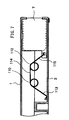
- a door member 7 is provided to cover the tape outlet extending over the upper housing 1 and the lower housing 2; two coil portions 110 and 112 are connected with each other via a medium arm portion 114; an arm portion 113 extending from the coil portion 110 is fixed to the housing, and the other arm portion 115 extending from the coil portion 112 is fixed to the door member 7, so that the door member 7 is constantly pushed by the coil spring towards the dosed position.
- each of the spring arm portions 113 and 115 moves using the respective ends of the arm as a fulcrum, thereby allowing the door member 7 to move to the opened position.
- the height of the spring is lower as compared with that of the spring with one coil portion, which allows larger moving distance of the door member 7 as compared with the case of the spring with one coil portion, in the cartridge having the smaller space between the upper wall and the lower wall.
- the coil portions 110 and 112 are arranged in tandem, and thus the distance between them are kept constant while the door member is shifting its position.
- relatively large space is required for the spring in the housing.
- portions of the door member or the housing may be subjected to abrasion by the arm portions of the spring, as the opening-closing movement of the door member is repeated.
- the present invention provides a tape cartridge including a housing, a single tape reel tumably held within the housing, said tape reel carrying a length of tape wound thereon, the outer end of the tape being fixed to a leader member in the form of pin, which can be taken out of the cartridge through an outlet formed in the housing by a tape draw-out member of a recording-reproducing apparatus, a door member covering said outlet, and a spring member pushing said door member towards the dosed position
- said spring member is a torsion coil spring comprising two coil portions; a connecting portion linking said two coil portions; a first arm portion that extends from one of said coil portions forming a first angle relative to said connecting portion and has an end abutting the housing; and a second arm portion extending from the other of said coil portions, forming a second angle relative to said connecting portion, said second angle pointing in a direction opposite to said first angle and having an end fixed to said
- the first arm portion is longer than the second arm portion.
- the first arm portion abutting the housing has an end in the form of a coil.
- the portion of the door member to which the spring member is fixed is provided with a hood that prevents the spring member from being brought into contact with the upper wall of the housing.
- the housing has a second abutting portion which functions as a fulcrum at the position apart from the above-mentioned abutting portion of the housing for the first arm portion, during the late stage of the deformation of the first arm portion, thereby shortening the effective length of the first arm portion, which allows the second arm portion to be deform ed as the door member is opened.
- Fig. 1 shows an exploded perspective view of the tape cartridge according to one embodiment of the present invention.
- the cartridge comprises a housing composed of the upper housing 1 and the lower housing 2, within which a single tape reel 3 is tumably held.
- the lower housing 2 has an opening 21 through which a drive shaft of the apparatus is inserted.
- notches 12 and 22 are formed respectively, and they together forms a tape outlet 100.
- a tape reel 3 comprises an upper flange 31, a lower flange 33 and a hub 32, the latter two of which are integrally formed together.
- a metal plate 34 is embedded on the bottom of the hub 32.
- On the bottom side of the hub 32 surrounding the metal plate 34 there formed dents arranged in circle (now shown) to engage with the drive shaft of the apparatus. Since the end of the tape is directly adhered to the outer surface of the hub by means of water or the like, the hub has no member for securing the tape.
- the inner surface of the hub 32 has engage dents 35, which engage with a brake lock 5, thereby preventing undesired rotation of the tape reel 3 when the cartridge is not in use.
- the bottom side of the brake lock 5 has engage dents 51, which engage with the dents 35 of the hub 32.
- the brake lock 5 is constantly pushed to the braking position by a brake spring 4.
- a guided projection 52 of the brake lock 5 is allowed to securely move upward or downward (to the braking position or to the brake-releasing position) by a position-regulating part 13 formed in the inner side of the upper housing 1.
- the brake-releasing plate 9 is composed of a main plate 91 and legs 92. Each of the legs 92 is inserted in the hole 36 on the bottom plate of the hub 32, and when the cartridge is applied to the apparatus, the legs 92 of the brake-releasing plate 9 is lifted upward, which leads to the upward lift of the brake lock 5, thereby releasing the engagement with tape reel 3 to allow the tape reel 3 to turn.
- the outer end of the tape T is fixed to the leader member 8.
- the leader member 8 is composed of a pin member 81 and a C-shaped damp 82.
- the tape T is wound around the pin member 81, and the C-shaped damp 82 is snap-fitted over the pin, with the tape end portion in between, thereby fixing the tape.
- the leader member 8 is held by a holding member of the apparatus, and then the tape T can be taken out.
- a tape outlet 100 is covered with a door member 7.
- the door member 7 is constantly pushed by a spring member 6 towards the position at which the door member doses the tape outlet 100.
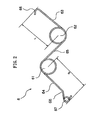
- Fig. 2 shows a plan view of the spring member 6 of the present invention.
- the spring member 6 is composed of first and second coil portions 61 and 62; a connecting portion 65 linking these coil portions 61 and 62; a first arm portion 64 extending from the first coil portion 61 (length: X); and a second arm portion 63 extending from the second coil portion 62 (length: r). As a whole, the spring member 6 is in the shape of N. The diameters of the two coil portions 61 and 62 are approximately the same, and the first arm portion 64 is longer than the second arm portion 63 (X > r).
- the first arm portion 64 has a bend portion 68 in between and a small coil portion 67 at the end, which abuts the spring-abutting portion 24 of the lower housing 2.
- the abutting portion 24 has a first abutting portion which is a comer formed by the projection and the housing inner surface, and a second abutting portion which is the top of the protrusion.
- the end of the second arm portion 63 has a U-shaped bend portion 66.
- Fig. 3 shows a perspective view of the door member 7. (a) shows a view from the outside, and (b) shows a view from the inside.
- the door member 7 has a main body 71; a projection 72 to be operated by the apparatus; and a portion 73 on which the spring is mounted.
- the portion 73 is one step lower as compared with the inner surface of the door, and as a result, the hood 74 is formed on the upper side of the portion 73.
- a mount hole 75a is formed in the perpendicular direction, through which the bend portion 66 of the second arm portion 63 is inserted.
- the outer surface of the portion 73 has the hole 75b, which is formed for shaping the mount hole 75a. In other words, among the four side walls of the hole 75b, the upper wall has an opening connected to the hole 75a.
- Fig. 4 shows a side view seen from inside of the housing wherein the spring member 6 is fixed to the door member 7. Because of the presence of the hood 74, the end of the bend portion 66 of the spring member 6 cannot shift upwardly further, even when the door member 7 slides. As a result, the end of the spring member cannot abrade the inner surface of the housing.
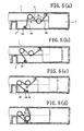
- Fig. 5 (a) - Fig. 5 (d) show steps of the movement of the torsion coil spring member 6 upon opening the door member towards left.
- Fig. 5 (a) shows a condition in which the door member is closed.
- the coil portion at the end of the first arm portion 64 is abutting against the corner at the base of the abutting portion 24.
- the first arm portion 64 is longer than the second arm portion 63, and when the spring is assembled in the cartridge, the angle ⁇ 1 formed by the first arm portion 64 and the connecting portion 65 is smaller than the angle ⁇ 2 formed by the second arm portion 63 and the connecting portion 65. This is because both arms are in equilibrium position where moments of force for both arms are identical.
- the arm portion angle ⁇ 1 on the side of the coil portion 61 becomes smaller while the first coil portion 61 moves passing the spring-abutting portion 24 (to the left side in the Figure), and the part of the arm portion 64 between the bend portion 68 and the end comes into contact with the spring-abutting portion 24.
- the first coil portion 61 is brought into contact with the wall 25 at about the same time as the bend portion 68 of the first arm portion 64 is brought into contact with the upper edge of the spring-abutting portion 24, which limits the further movement of the first coil portion 61.
- Fig. 6 shows a plan view of the lower housing.
- the spring-abutting portion 24 is formed at the end of the door member guide groove 23 of the lower housing 2.
- the height should be low so as to allow the first coil portion 61 to shift fully to the back and the bend portion 68 of the first arm portion 64 to be brought into contact with the upper edge of the portion 24.
- the coil portion 67 is formed which abuts with the spring-abutting portion 24.
- the portion 67 in the form of coil allows smooth movement of the spring member 6 along with the movement of the door member 7.
- the coil has a certain width, tilting of the spring member 6 upon assembling the spring member 6 into the housing can be avoided, leading to prevention of the trouble upon covering the lower housing 2 with the upper housing 1.
- the end of the arm portion abutting the housing is in the form of coil, the abrasion of the housing can be prevented. Further, since the end of the arm portion can be provided with a certain width, tilting of the spring member upon assembling the housing can be avoided.
- the door member has a hood which prevent the end of the arm portion of the spring member from being brought into contact with the inner surface of the housing, abrasion of the housing by the spring member upon opening/closing the door can be avoided.
- the housing has a projection which functions as a fulcrum at the position apart from the above-mentioned abutting portion for the first arm portion during the late stage of the deformation of the first arm portion, when the door member opens, firstly the first arm portion abutting the housing begins to deform, and then the second arm portion fixed to the door member begins to deform. As the result, the force required for the initial movement for opening the door member is kept small, and the smooth movement is provided.
Landscapes
- Packaging Of Annular Or Rod-Shaped Articles, Wearing Apparel, Cassettes, Or The Like (AREA)
- Springs (AREA)
- Tape Measures (AREA)
Abstract
Description
wherein said spring member is a torsion coil spring comprising two coil portions; a connecting portion linking said two coil portions; a first arm portion that extends from one of said coil portions forming a first angle relative to said connecting portion and has an end abutting the housing; and a second arm portion extending from the other of said coil portions, forming a second angle relative to said connecting portion, said second angle pointing in a direction opposite to said first angle and having an end fixed to said door member.
Claims (5)
- A tape cartridge including a housing, a single tape reel tumably held within the housing, said tape reel carrying a length of tape wound thereon, the outer end of the tape being fixed to a leader member in the form of pin, which can be taken out of the cartridge through an outlet formed in the housing by a tape draw-out member of a recording-reproducing apparatus, a door member covering said outlet, and a spring member pushing said door member towards the dosed position,
characterized in that said spring member is a torsion coil spring comprising two coil portions; a connecting portion linking said two coil portions; a first arm portion that extends from one of said coil portions forming a first angle relative to said connecting portion and has an end abutting the housing; and a second arm portion extending from the other of said coil portions, forming a second angle relative to said connecting portion, said second angle pointing in a direction opposite to said first angle and having an end fixed to said door member. - The tape cartridge according to Claim 1, wherein said first arm portion is longer than said second arm portion, such that when the door member is opened, said first arm portion abutting the housing is deformed at first , and then said second arm portion fixed to the door member is deformed.
- The tape cartridge according to Claim 1 or 2, wherein the end of the first arm portion abutting the housing is in the form of a coil.
- The tape cartridge according to any one of Claims 1 to 3, wherein a portion of the door member to which the spring member is fixed is provided with a hood that prevents the spring member from being brought into contact with the upper wall of the housing.
- The tape cartridge according to any one of Claims 1 to 4, wherein said housing has a second abutting portion which functions, during the late stage of the deformation of said first arm portion, as a fulcrum at a position apart from the abutting portion of the housing for said first arm portion, said fulcrum shortening the effective length of the first arm portion so as to allow the second arm portion to be deformed as the door member opens.
Applications Claiming Priority (3)
| Application Number | Priority Date | Filing Date | Title |
|---|---|---|---|
| JP2000288592A JP4092063B2 (en) | 2000-09-22 | 2000-09-22 | Tape cartridge |
| JP2000288592 | 2000-09-22 | ||
| PCT/JP2001/008189 WO2002025663A1 (en) | 2000-09-22 | 2001-09-20 | Tape cartridge |
Publications (2)
| Publication Number | Publication Date |
|---|---|
| EP1327986A1 true EP1327986A1 (en) | 2003-07-16 |
| EP1327986A4 EP1327986A4 (en) | 2007-07-11 |
Family
ID=18772159
Family Applications (1)
| Application Number | Title | Priority Date | Filing Date |
|---|---|---|---|
| EP01967751A Withdrawn EP1327986A4 (en) | 2000-09-22 | 2001-09-20 | Tape cartridge |
Country Status (4)
| Country | Link |
|---|---|
| US (1) | US6702216B2 (en) |
| EP (1) | EP1327986A4 (en) |
| JP (1) | JP4092063B2 (en) |
| WO (1) | WO2002025663A1 (en) |
Families Citing this family (10)
| Publication number | Priority date | Publication date | Assignee | Title |
|---|---|---|---|---|
| JP3739579B2 (en) * | 1998-11-20 | 2006-01-25 | 富士写真フイルム株式会社 | Magnetic tape cartridge |
| JP4153684B2 (en) * | 2001-05-24 | 2008-09-24 | 富士フイルム株式会社 | Magnetic tape cartridge |
| JP2005500690A (en) | 2001-08-13 | 2005-01-06 | ハネウェル・インターナショナル・インコーポレーテッド | Providing current control of a semiconductor device carried on a wafer using an overlayer pattern |
| JP4054236B2 (en) * | 2002-08-30 | 2008-02-27 | 富士フイルム株式会社 | Recording tape cartridge |
| JP4656817B2 (en) | 2003-03-27 | 2011-03-23 | Tdk株式会社 | Tape cartridge door member and tape cartridge |
| JP4645012B2 (en) * | 2003-09-09 | 2011-03-09 | Tdk株式会社 | Assembly equipment and manufacturing equipment |
| US7290734B2 (en) | 2003-12-22 | 2007-11-06 | Tdk Corporation | Tape reel and information recording medium |
| JP2006018868A (en) | 2004-06-30 | 2006-01-19 | Tdk Corp | Cartridge case and information recording medium |
| US7258295B2 (en) | 2005-01-26 | 2007-08-21 | Tdk Corporation | Cartridge case and information recording medium |
| EP1936925B1 (en) * | 2006-12-21 | 2011-08-31 | Sharp Kabushiki Kaisha | Torsion coil spring and sliding type mobile terminal equipped therewith |
Family Cites Families (8)
| Publication number | Priority date | Publication date | Assignee | Title |
|---|---|---|---|---|
| JP3564851B2 (en) | 1996-03-05 | 2004-09-15 | ソニー株式会社 | Disk cartridge |
| JPH1064222A (en) | 1996-08-15 | 1998-03-06 | Sony Corp | Disk cartridge |
| JP3695921B2 (en) | 1997-12-22 | 2005-09-14 | 富士写真フイルム株式会社 | Magnetic tape cartridge |
| JP3658516B2 (en) * | 1998-03-16 | 2005-06-08 | 日立マクセル株式会社 | Cartridge for recording medium |
| JP3651649B2 (en) * | 1998-03-16 | 2005-05-25 | 日立マクセル株式会社 | Single reel type magnetic tape cartridge |
| US5927633A (en) * | 1998-07-22 | 1999-07-27 | Hewlett-Packard Company | Resiliently biased parking seat for receiving the leader pin of a single reel tape cartridge |
| US6411466B1 (en) * | 1999-05-25 | 2002-06-25 | Tdk Corporation | Tape cartridge |
| JP2001057047A (en) * | 1999-08-11 | 2001-02-27 | Tdk Corp | Tape cartridge |
-
2000
- 2000-09-22 JP JP2000288592A patent/JP4092063B2/en not_active Expired - Fee Related
-
2001
- 2001-09-20 WO PCT/JP2001/008189 patent/WO2002025663A1/en not_active Ceased
- 2001-09-20 US US10/130,838 patent/US6702216B2/en not_active Expired - Lifetime
- 2001-09-20 EP EP01967751A patent/EP1327986A4/en not_active Withdrawn
Also Published As
| Publication number | Publication date |
|---|---|
| JP4092063B2 (en) | 2008-05-28 |
| WO2002025663A1 (en) | 2002-03-28 |
| US20020170998A1 (en) | 2002-11-21 |
| JP2002100148A (en) | 2002-04-05 |
| EP1327986A4 (en) | 2007-07-11 |
| US6702216B2 (en) | 2004-03-09 |
Similar Documents
| Publication | Publication Date | Title |
|---|---|---|
| US6702216B2 (en) | Tape cartridge | |
| US6264126B1 (en) | Tape cartridge | |
| US20020029523A1 (en) | Guiding structure for moving member | |
| EP1058259B1 (en) | Tape cartridge | |
| EP0944083B1 (en) | Recording medium cartridge with spring-biased shutter | |
| US5717554A (en) | Lid locking member for a tape cassette | |
| US20020003351A1 (en) | Drive apparatus of trunk lid lock for motor vehicle | |
| JPH0755723Y2 (en) | Disk storage case | |
| EP0911208A1 (en) | Seat slide apparatus | |
| JP4112160B2 (en) | Tape cartridge | |
| RU2066480C1 (en) | Cassette with magnetic tape, which is mounted on two coils located in one plane | |
| JP4656817B2 (en) | Tape cartridge door member and tape cartridge | |
| US6215619B1 (en) | Tape cassette with reel brake release lever | |
| JP3163828B2 (en) | Vehicle door lock device | |
| JPH07182819A (en) | Disk cartridge | |
| JPH0230620Y2 (en) | ||
| JPH10247374A (en) | Magnetic tape cassette | |
| EP1011104B1 (en) | Tape cassette | |
| US6137653A (en) | Release mechanism for a reel brake member for a tape cassette | |
| JP4377998B2 (en) | Tape cartridge | |
| JPH1166810A (en) | Magnetic tape cartridge | |
| GB2338950A (en) | Tape cassettes | |
| JPH054158Y2 (en) | ||
| JPS581907Y2 (en) | tape cassette | |
| JP2917493B2 (en) | Tape cassette |
Legal Events
| Date | Code | Title | Description |
|---|---|---|---|
| PUAI | Public reference made under article 153(3) epc to a published international application that has entered the european phase |
Free format text: ORIGINAL CODE: 0009012 |
|
| 17P | Request for examination filed |
Effective date: 20020511 |
|
| AK | Designated contracting states |
Designated state(s): AT BE CH CY DE DK ES FI FR GB GR IE IT LI LU MC NL PT SE TR |
|
| AX | Request for extension of the european patent |
Extension state: AL LT LV MK RO SI |
|
| RBV | Designated contracting states (corrected) |
Designated state(s): GB |
|
| REG | Reference to a national code |
Ref country code: DE Ref legal event code: 8566 |
|
| A4 | Supplementary search report drawn up and despatched |
Effective date: 20070613 |
|
| 17Q | First examination report despatched |
Effective date: 20070827 |
|
| STAA | Information on the status of an ep patent application or granted ep patent |
Free format text: STATUS: THE APPLICATION IS DEEMED TO BE WITHDRAWN |
|
| 18D | Application deemed to be withdrawn |
Effective date: 20080108 |