EP1327933A2 - Apparatus and method for controlling recursion at system startup - Google Patents
Apparatus and method for controlling recursion at system startup Download PDFInfo
- Publication number
- EP1327933A2 EP1327933A2 EP03250155A EP03250155A EP1327933A2 EP 1327933 A2 EP1327933 A2 EP 1327933A2 EP 03250155 A EP03250155 A EP 03250155A EP 03250155 A EP03250155 A EP 03250155A EP 1327933 A2 EP1327933 A2 EP 1327933A2
- Authority
- EP
- European Patent Office
- Prior art keywords
- recursion
- level
- device tree
- tree nodes
- processor
- Prior art date
- Legal status (The legal status is an assumption and is not a legal conclusion. Google has not performed a legal analysis and makes no representation as to the accuracy of the status listed.)
- Withdrawn
Links
Images


Classifications
-
- G—PHYSICS
- G06—COMPUTING OR CALCULATING; COUNTING
- G06F—ELECTRIC DIGITAL DATA PROCESSING
- G06F9/00—Arrangements for program control, e.g. control units
- G06F9/06—Arrangements for program control, e.g. control units using stored programs, i.e. using an internal store of processing equipment to receive or retain programs
- G06F9/44—Arrangements for executing specific programs
- G06F9/4401—Bootstrapping
-
- G—PHYSICS
- G06—COMPUTING OR CALCULATING; COUNTING
- G06F—ELECTRIC DIGITAL DATA PROCESSING
- G06F9/00—Arrangements for program control, e.g. control units
- G06F9/06—Arrangements for program control, e.g. control units using stored programs, i.e. using an internal store of processing equipment to receive or retain programs
- G06F9/44—Arrangements for executing specific programs
- G06F9/4401—Bootstrapping
- G06F9/4411—Configuring for operating with peripheral devices; Loading of device drivers
Definitions
- This invention relates generally to managing processor-based system resources, and more particularly, to controlling recursion during system startup.
- BIOS Basic Input Output System
- the BIOS is low-level system software that provides an interface between the system hardware (e.g., the chipset and processor) and the operating system.
- the BIOS is generally encoded in nonvolatile read-only memory (“ROM”) so that it may be executed at system startup.
- ROM nonvolatile read-only memory
- the BIOS is generally written in low-level assembly language. Because the BIOS is closely tied to the hardware configurations of a particular machine, the BIOS is typically machine-dependent. Therefore, a BIOS written for a one machine may not execute properly on another machine. Accordingly, programmers often write different versions of the BIOS to cover different machines.
- Boot firmware is ROM-based software that is typically executed when a processor-based system is turned on.
- a primary function of boot firmware is to initialize the hardware and to execute (i.e ., "boot") the operating system.
- Secondary functions of boot firmware include testing the hardware, managing hardware configuration information, and providing various tools for debugging faulty hardware or software in the processor-based system.
- boot firmware may be system-independent.
- One example of a system-independent boot firmware is "Open Firmware.”
- Open Firmware is a non-proprietary standard for boot firmware that may be utilized on different processors and busses. Open Firmware was first developed in the late 1980s at Sun® Microsystems, and was designed to be independent of any particular microprocessor or hardware system design. Today, Open Firmware is firmware that complies with IEEE Standard 1275-1994. By providing an interface independent of processor types, Open Firmware allows, among other things, a peripheral device added to the processor-based system to identify itself and supply a boot driver that will allow the device to be utilised on the system.
- Open Firmware also includes a user interface with debugging capabilities that allow operating systems and system loaders to utilize boot firmware to assist in a system configuration and initialization process. Open Firmware also provides a processor-independent mechanism by which a system can interrogate and configure expansion devices and install device drivers.
- Open Firmware is support for self-identifying devices.
- the driver for the device is generally stored on the device itself, typically in a nonvolatile memory on the device.
- the nonvolatile memory may be, for example, an erasable and programmable read-only memory (EPROM).
- EPROM erasable and programmable read-only memory
- Open Firmware may encode the drivers in a machine-independent language called FCode, a byte-coded intermediate language similar to the Forth programming language, but encoded as a sequence of binary byte codes representing a defined set of Forth definitions. Forth is based on a stack-oriented virtual machine that may be implemented on virtually any computer.
- Open Firmware may deal directly with hardware devices in the processor-based system.
- the operating system may deal with hardware devices in the processor-based system.
- the FCode encoded in the device may comprise a variety of information about the device, including a unique name representing the type of device and where that device is located in the processor-based system addressing structure.
- Open Firmware may build a device tree, which, in one embodiment, is a hierarchical data structure describing the devices attached to the processor-based system. Open Firmware typically builds the device tree in a memory of the processor-based system, such as a random-access memory (RAM).
- RAM random-access memory
- USB Universal Serial Bus
- Open Firmware may create a device tree comprising several levels of USB hubs and USB devices.
- the plurality of levels of USB hubs and USB devices may, however, create an overflow of internal structures in the memory of the processor-based system, such that the device tree cannot be successfully built.
- a method for controlling recursion at system startup.
- the method comprises creating one or more levels of device tree nodes branching from a root node, wherein the number of levels of device tree nodes is equal to a recursion depth.
- a method for controlling recursion at system startup.
- the method comprises incrementing a recursion level and creating a level of device tree nodes branching from a root node or another level of device tree nodes, wherein the recursion level is less than a recursion depth.
- a method for controlling recursion at system startup.
- the method comprises initializing a recursion level, creating a level of device tree nodes, incrementing the recursion level, and comparing the recursion level to a recursion depth and discontinuing the process of incrementing the recursion level and creating the level of device tree nodes in response to the recursion level being equal to the recursion depth.
- an article comprising one or more machine-readable storage media containing instructions for controlling recursion at system startup.
- the one or more instructions when executed, cause a processor to create one or more levels of device tree nodes branching from a root node, wherein the number of levels of device tree nodes is equal to a recursion depth.
- an article comprising one or more machine-readable storage media containing instructions for controlling recursion at system startup.
- the one or more instructions when executed, cause a processor to increment a recursion level and create a level of device tree nodes branching from a root node or another level of device tree nodes, wherein the recursion level is less than a recursion depth.
- an article comprising one or more machine-readable storage media containing instructions for controlling recursion at system startup.
- the one or more instructions when executed, cause a processor to initialize a recursion level, create a level of device tree nodes, increment the recursion level, and compare the recursion level to a recursion depth and discontinue the process of incrementing the recursion level and creating the level of device tree nodes in response to the recursion level being equal to the recursion depth.
- an apparatus for controlling recursion at system startup.
- the apparatus is comprised of a storage unit adapted to store a recursion control process and a control unit adapted to execute the recursion control process, wherein the recursion control process causes the control unit to control recursion during system startup.
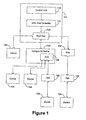
- a processor-based system 104 coupled to a plurality of USB devices 108 in accordance with one embodiment of the present invention, is shown.
- devices such as printers, monitors, keyboards, auxiliary storage drives and scanners may connect to a host device, usually a processor-based system 104, through the USB host controller 112 in a tiered star topology.
- the processor-based system 104 may be one of a variety of devices, such as a personal computer, a cellular phone, a personal digital assistant (PDA), an Internet appliance, or any other device having one or more processors.
- PDA personal digital assistant
- the USB host controller 112 is at the center of the tiered star topology with the control unit 116 on the upper tier and the devices 108 on the lower tier,
- the control unit 116 of the processor-based system 104 may be a microprocessor, a microcontroller, a digital signal processor, a processor card (including one or more microprocessors or controllers), or other control or computing devices.
- the control unit 116 may be coupled to a storage unit (not shown).
- the storage unit may include one or more machine-readable storage media for storing information.
- the storage media may be optical or magnetic in nature.
- the storage media may include different forms of memory including semiconductor memory devices such as dynamic or static random access memories (DRAMs or SRAMs), erasable and programmable read-only memories (EPROMs), etectrically erasable and programmable read-only memories (EBPROMs) and flash memories; magnetic disks such as fixed, floppy, removable disks; other magnetic media including tape; and optical media such as compact disks (CDs) or digital video disks (DVDs).
- DRAMs or SRAMs dynamic or static random access memories
- EPROMs erasable and programmable read-only memories
- EBPROMs etectrically erasable and programmable read-only memories
- CDs compact disks
- DVDs digital video disks
- the USB host controller 112 connects to the PCI bus (not shown) of the processor-based system 104.
- the USB host controller 112 connects to the devices 108 via a root hub 120.
- the devices 108 can also function as hubs, as illustrated by a compound device 124 that has a hub 128 as part of the compound device 124.
- the hub 128 of the compound device 124 allows a plurality of other devices 108 to be connected to the processor-based system 104.
- the compound device 124 may have its own functionality, such as a keyboard that allows connection of a joystick directly to the keyboard. Additional hubs 132 are connected to the root hub 120 and to downstream ports of the compound device 124 to expand the number of devices 108 connectable to the processor-based system 104,
- USB tiered star topology is used throughout the present disclosure solely for the purposes of illustrating limiting the amount of recursion during the creation of a device tree at system startup.
- the device tree may be created for devices other than USB devices, and any hierarchical device structure connected to the processor-based system 104, such as the USB tiered star topology, may be utilized.
- FIG 2 is a diagram illustrating a standardized bus interface, such as a conventional computer system 200, that may include a processor-based system 104 and a device 108 of Figure 1.
- a Universal Serial Bus (USB) 204 connects the device 108 to the processor-based system 104
- the processor-based system 104 may include a control unit 116 of Figure 1 connected to a USB interface 208.
- the USB interface 208 comprises the USB host controller 112 and the root hub 120 of Figure 1.
- the USB interface 208 may comprise one of a variety of combinations of circuitry and software, such that the plurality of USB devices 108 can be attached to the processor-based system 104.
- the control unit 116 executes software application code located in a storage unit 212 and communicates data to and from the device 108 through the USB interface 208 and the USB 204.
- the processor-based system 104 also includes an operating system 216 that includes a software device driver 220.
- the software device driver 220 is stored in the storage unit 212.
- the software device driver 220 is a program that extends the operating system 216 to support hardware devices such as sound cards, printers, scanners, CD-ROM drives, and the like.
- the device 108 may include a USB interface 224, a control unit 228, and an internal memory 232 that may store configuration information describing the characteristics of the device.
- the internal memory 232 may take the form of any nonvolatile memory, including all forms of read-only memory (ROM) such as programmable read-only memories (PROMs), erasable and programmable read-only memories (EPROMs), electrically erasable and programmable read-only memories (EEPROMs), flash memory, and the like.
- ROM read-only memory
- PROMs programmable read-only memories
- EPROMs erasable and programmable read-only memories
- EEPROMs electrically erasable and programmable read-only memories
- flash memory and the like.
- the internal memory 232 may also take the form of a random access memory (RAM), including dynamic or static random access memories (DRAMs or SRAMs).
- the internal memory 232 of the device 108 comprises an FCode module 236.
- the FCode module 236 comprises machine-independent drivers that provide functionality for the processor-based system 104 to operate the device 108.
- FCode modules are generally hard-coded on the internal memory 232 in the FCode programming language.
- the phrase "machine-independent" generally means that the same FCode driver can be used on systems with different processor types. For example, the same FCode driver may be used for an Intel® Pentium® processor, an AMD® Athlon® processor, and a Sun® SPARC®.
- FIG. 1 For clarity and case of illustration, only selected functional blocks of the processor-based system 104 arc illustrated in Figures 1 and 2, although those skilled in the art will appreciate that the processor-based system 104 may comprise additional or fewer functional blocks. Additionally, it should be appreciated that Figures 1 and 2 illustrate one possible configuration of the processor-based system 104 and that other configurations comprising different interconnections may also be possible.
- the software-implemented described herein are typically encoded on some form of program storage medium or implemented over some type of transmission medium.
- the program storage medium may be magnetic (e.g ., a floppy disk or a hard drive) or optical (e.g ., a compact disc read only memory, or "CD ROM”), and may be read only or random access.
- the transmission medium may be twisted wire pairs, coaxial cable, optical fiber, or some other suitable transmission medium known to the art.
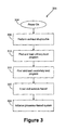
- boot sequence 300 in accordance with one embodiment of the present invention, is shown.
- the power for the processor-based system 104 is turned on (at 304).
- a programmable read-only memory (not shown) (hereinafter referred to as a "boot PROM”) on the processor-based system 104 performs (at 308) self-test diagnostics to verify the hardware and software of the processor-based system 104.
- a power-on self test (“POST'") is executed to determine if the keyboard, random access memory (“RAM”), disk drives, and other hardware are working correctly. If the hardware is not detected or is found not to be operating properly, an error indication may be displayed following the failure.
- the error indication may comprise text on the display screen or a series of coded beeps, depending on the nature of the problem and the particular implementation of the POST. Furthermore, because the hardware checked by the POST may he essential to the operation of the processor-based system 104, an error found in the POST may be fatal and cause the boot sequence 300 to stop executing.
- the boot PROM comprises a default boot device that contains the software to begin loading a kernel (described in greater detail below) into the processor-based system 104.
- the primary boot program is found and loaded (at 312) from the default boot device into the storage unit 212 of the processor-based system 104.
- the primary boot program initializes some of the peripherals and memory of the processor-based system 104.
- a primary boot program finds and loads (at 316) a secondary boot program.
- the secondary boot program may be found in the storage unit 212 of the processor-based system 104.
- the secondary boot program comprises a device driver, which contains a kernel.
- the secondary boot program loads (at 320) the kernel.
- the kernel may comprise at least one of a platform-specific kernel and a generic kernel.
- the kernel may be found in the storage unit 212 of the processor-based system 104.
- the kernel initializes itself, loads the necessary modules to mount the root file system, and checks for the presence of devices, such as graphic displays, Ethernet controllers, disk controllers, disk drives, and tape devices.
- the kernel also starts (at 324) the initialization process of the processor-based system 104.
- the initialisation process may be a series of steps performed by the processor-based system 104.
- the initialization process is provided by initialization files and scripts in the storage unit 212 of the processor-based system 104.
- the initialization files and scripts may cause the processor-based system 104 to check and mount file systems and perform various maintenance tasks.
- the initialization process may cause llic processor-based system 104 to create hardware device trees for the devices 108 attached to the processor-based system 104.
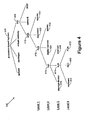
- the device true 400 may be a hierarchical data structure describing the devices 108 attached to the processor-based system 104.
- the device tree 400 is one method for organizing the devices 108 attached to the processor-based system 104. Both a user and an application may determine the hardware configuration of a particular system by inspecting the device tree 400.
- the devices 108 may be attached to the processor-based system 104 through a hierarchy of interconnected buses. The interconnected buses and their devices may be represented as a tree of nodes.
- Trees are generally recursive functions. This is generally because recursion may store a plurality of information at each level and allow a user to come back to that stale in the future by using tree traversal routines, in accordance with conventional practice. In an iterative solution, for example, separate variables may need to be allocated and managed to maintain the various tree levels. Recursion may provide a simpler solution for forming the tree because a recursive structure, by definition, may involve the storage of previous information.
- a recursive function is a function that calls itself repeatedly on a plurality of levels.
- a recursive structure such as a tree, may have itself as its own children, and is thus considered recursive.
- Recursive structures may utilize large amounts of memory. For example, if the recursive structure calls itself a plurality of times, then a plurality of copies of the same structure may be simultaneously stored in memory. This overhead from the recursive structure may cause an overflow in memory such that a particular tree may not be created properly,
- a node representing the processor-based system's 104 main physical address bus forms the device tree's 400 root node 404.
- Nodes with children usually represent buses and their associated controllers, if any.
- Each such node defines a physical address space that distinguishes the devices 108 connected to the node from one another.
- Each child of that node is assigned a physical address in the parent's address space.
- the physical address generally represents a physical characteristic unique to the device 108, such as a bus address or a slot number where the device 108 is installed.
- the use of physical addresses to identify devices may prevent device addresses from changing when other devices are installed or removed.
- Nodes without children are known as "leaf nodes" and generally represent the devices 108. However, leaf nodes may represent other items, such as system-supplied firmware services.
- a peripheral component interconnect (PCI) bus 408 branches from the root node 404.
- PCI peripheral component interconnect
- USB universal serial bus
- Branching from the USB 412 are four levels of devices 108, including three hubs 416, a keyboard 420, a mouse 424, a digital camera 428, a printer 432, a storage device 436, a scanner 440, a webcam 444, a digital video disc (DVD) drive 448, and a personal digital assistant (PDA) 452.
- PDA personal digital assistant
- a device tree 400 may contain more or fewer nodes (i.e ., devices 108) than the device tree 400 illustrated in Figure 4.
- the device tree 400 may be implemented in any manner in accordance with conventional practice.
- the USB host controller 112 of Figure 1 may publish one or more properties, which represent some characteristics of the device tree 500. Those properties may be viewed by the Open Firmware at any time during the creation or the device tree 500.
- the device tree 500 comprises two properties: a recursion depth 504 and a recursion level 508, 512, 516.
- the device tree 500 is typically created once all the devices 108 attached to the processor-based system 104 have been located. In some circumstances, this may mean spanning several levels of hubs 416 and devices 108, as illustrated in Figure 5A.
- the USB host controller 112 of Figure 1 may provide the recursion depth 504.
- the recursion depth 504 provides a limit as to the number of levels in the device tree 500 that the Open Firmware can create.
- the Open Firmware may terminate the creation of the device tree 500 when it reaches a level equal to the recursion depth 504.
- the operating system 216 of Figure 2 may apply the device driver 220 to locate the remaining devices 108 that are not mapped on the device tree 500.
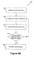
- FIG. 5B a flow diagram illustrating a method of controlling recursion during the formation of the device trees (hereinafter referred to as a "recursion control process" 600) is shown.
- the recursion level is initialized (at 604) to zero.
- the recursion level in one embodiment, provides a counter such that the Open Firmware can keep trade of whether it has reached the recursion depth 504.
- the recursion level 508, 512, 516 is incremented (at 612) by one and compared to the recursion depth 504 (at 616).
- each level of nodes may inherit the recursion level 508, 512, 516 from its parent, decrement the recursion level 508, 512, 516, and publish the decremented recursion level 508, 512, 516 for its children. If the recursion level 508, 512, 516 is less than the recursion depth 504, additional levels of nodes are created (at 608, 612, 616) until the recursion level 508, 512, 516 is not less than the recursion depth 504. If the recursion is not less than the recursion depth 504, then further recursion terminates (at 620), and therefore, the process creating the device tree 500 terminates.
- the device tree 500 with two levels of USB hubs 416 and USB devices 108 is created.
- the recursion level 508 is initialized (at 604) to zero and a first level of device tree nodes is created (at 608).
- the resulting device tree 500 after the process terminates (at 620) is the device tree 500 that is formed during the boot sequence 300 of Figure 3.
- the operating system 216 operates in a conventional manner to locate the remaining devices 108 in the device tree 400 of Figure 4 that fall below the recursion depth 504.
Landscapes
- Engineering & Computer Science (AREA)
- Software Systems (AREA)
- Theoretical Computer Science (AREA)
- Computer Security & Cryptography (AREA)
- Physics & Mathematics (AREA)
- General Engineering & Computer Science (AREA)
- General Physics & Mathematics (AREA)
- Stored Programmes (AREA)
Abstract
The present invention provide a method and apparatus for controlling recursion at
system startup. The method comprises creating one or more levels of device tree nodes
branching from a root node, wherein the number of levels of device tree nodes is equal to a
recursion depth. The apparatus comprises a storage unit adapted to store a recursion control
process and a control unit adapted to execute the recursion control process, wherein the
recursion control process causes the control unit to control recursion during system startup.
Description
- This invention relates generally to managing processor-based system resources, and more particularly, to controlling recursion during system startup.
- In most processor-based systems, a Basic Input Output System ("BIOS") is required at startup. The BIOS is low-level system software that provides an interface between the system hardware (e.g., the chipset and processor) and the operating system. The BIOS is generally encoded in nonvolatile read-only memory ("ROM") so that it may be executed at system startup. Furthermore, the BIOS is generally written in low-level assembly language. Because the BIOS is closely tied to the hardware configurations of a particular machine, the BIOS is typically machine-dependent. Therefore, a BIOS written for a one machine may not execute properly on another machine. Accordingly, programmers often write different versions of the BIOS to cover different machines.
- Instead of the BIOS, some processor-based systems employ "boot firmware" at system startup. Boot firmware is ROM-based software that is typically executed when a processor-based system is turned on. A primary function of boot firmware is to initialize the hardware and to execute (i.e., "boot") the operating system. Secondary functions of boot firmware include testing the hardware, managing hardware configuration information, and providing various tools for debugging faulty hardware or software in the processor-based system.
- One advantage of boot firmware over BIOS is that boot firmware may be system-independent. One example of a system-independent boot firmware is "Open Firmware." Open Firmware is a non-proprietary standard for boot firmware that may be utilized on different processors and busses. Open Firmware was first developed in the late 1980s at Sun® Microsystems, and was designed to be independent of any particular microprocessor or hardware system design. Today, Open Firmware is firmware that complies with IEEE Standard 1275-1994. By providing an interface independent of processor types, Open Firmware allows, among other things, a peripheral device added to the processor-based system to identify itself and supply a boot driver that will allow the device to be utilised on the system. Open Firmware also includes a user interface with debugging capabilities that allow operating systems and system loaders to utilize boot firmware to assist in a system configuration and initialization process. Open Firmware also provides a processor-independent mechanism by which a system can interrogate and configure expansion devices and install device drivers.
- One useful Open Firmware feature is support for self-identifying devices. In a firmware environment, the driver for the device is generally stored on the device itself, typically in a nonvolatile memory on the device. The nonvolatile memory may be, for example, an erasable and programmable read-only memory (EPROM). Instead of storing those drivers in machine language, Open Firmware may encode the drivers in a machine-independent language called FCode, a byte-coded intermediate language similar to the Forth programming language, but encoded as a sequence of binary byte codes representing a defined set of Forth definitions. Forth is based on a stack-oriented virtual machine that may be implemented on virtually any computer.
- In one embodiment, Open Firmware may deal directly with hardware devices in the processor-based system. In another embodiment, the operating system may deal with hardware devices in the processor-based system. The FCode encoded in the device may comprise a variety of information about the device, including a unique name representing the type of device and where that device is located in the processor-based system addressing structure. Using the FCode encoded in the device, Open Firmware may build a device tree, which, in one embodiment, is a hierarchical data structure describing the devices attached to the processor-based system. Open Firmware typically builds the device tree in a memory of the processor-based system, such as a random-access memory (RAM).
- Some bus standards support a simultaneous connection of a plurality of devices to the bus. For example, the Universal Serial Bus (USB) supports up to 127 devices at one time. Open Firmware may create a device tree comprising several levels of USB hubs and USB devices. The plurality of levels of USB hubs and USB devices may, however, create an overflow of internal structures in the memory of the processor-based system, such that the device tree cannot be successfully built.
- In one aspect of the present invention, a method is provided for controlling recursion at system startup. The method comprises creating one or more levels of device tree nodes branching from a root node, wherein the number of levels of device tree nodes is equal to a recursion depth.
- In another aspect of the present invention, a method is provided for controlling recursion at system startup. The method comprises incrementing a recursion level and creating a level of device tree nodes branching from a root node or another level of device tree nodes, wherein the recursion level is less than a recursion depth.
- In another aspect of the present invention, a method is provided for controlling recursion at system startup. The method comprises initializing a recursion level, creating a level of device tree nodes, incrementing the recursion level, and comparing the recursion level to a recursion depth and discontinuing the process of incrementing the recursion level and creating the level of device tree nodes in response to the recursion level being equal to the recursion depth.
- In another aspect of the present invention, an article comprising one or more machine-readable storage media containing instructions is provided for controlling recursion at system startup. The one or more instructions, when executed, cause a processor to create one or more levels of device tree nodes branching from a root node, wherein the number of levels of device tree nodes is equal to a recursion depth.
- In another aspect of the present invention, an article comprising one or more machine-readable storage media containing instructions is provided for controlling recursion at system startup. The one or more instructions, when executed, cause a processor to increment a recursion level and create a level of device tree nodes branching from a root node or another level of device tree nodes, wherein the recursion level is less than a recursion depth.
- In another aspect of the present invention, an article comprising one or more machine-readable storage media containing instructions is provided for controlling recursion at system startup. The one or more instructions, when executed, cause a processor to initialize a recursion level, create a level of device tree nodes, increment the recursion level, and compare the recursion level to a recursion depth and discontinue the process of incrementing the recursion level and creating the level of device tree nodes in response to the recursion level being equal to the recursion depth.
- In yet another aspect of the present invention, an apparatus is provided for controlling recursion at system startup. The apparatus is comprised of a storage unit adapted to store a recursion control process and a control unit adapted to execute the recursion control process, wherein the recursion control process causes the control unit to control recursion during system startup.
- Various embodiments of the invention will now, by way of example only, be described in detail, in conjunction with the accompanying drawings, in which like reference numerals identify like elements, and in which:
- Figure 1 illustrates a block diagram of a processor-based system programmed and operated in accordance with one embodiment of the present invention;
- Figure 2 illustrates an alternate block diagram of the processor-based system of Figure 1, programmed and operated in accordance with one embodiment of the present invention;
- Figure 3 illustrates a flow diagram of a boot sequence that may be implemented by the processor-based systems of Figures 1 and 2, in accordance with one embodiment of the present invention;
- Figure 4 illustrates a device tree that may be formed during the boot sequence of Figure 3, in accordance with one embodiment of the present invention;
- Figure 5A illustrates an alternate device tree that may be formed during the boot sequence of Figure 3, in accordance with one embodiment of the present invention; and
- Figure 5B illustrates a flow diagram of a method of controlling recursion during the formation of the device trees of Figures 4 and 5A, in accordance with one embodiment of the present invention.
-
- Illustrative embodiments of the invention are described below. In the interest of clarity, not all features of an actual implementation are described in this specification. It will of course be appreciated that in the development of any such actual embodiment, numerous implementation-specific decisions must be made to achieve the developers' specific goals, such as compliance with system-related and business-related constraints, which will vary from one implementation to another. Moreover, it will be appreciated that while such a development effort might be complex and time-consuming, it would nevertheless be a routino undertaking for those of ordinary skill in the art having the benefit of this disclosure.
- Turning now to Figure 1, a processor-based
system 104 coupled to a plurality ofUSB devices 108, in accordance with one embodiment of the present invention, is shown. In the illustrated embodiment, devices such as printers, monitors, keyboards, auxiliary storage drives and scanners may connect to a host device, usually a processor-basedsystem 104, through theUSB host controller 112 in a tiered star topology. The processor-basedsystem 104 may be one of a variety of devices, such as a personal computer, a cellular phone, a personal digital assistant (PDA), an Internet appliance, or any other device having one or more processors. Typically, theUSB host controller 112 is at the center of the tiered star topology with thecontrol unit 116 on the upper tier and thedevices 108 on the lower tier, Thecontrol unit 116 of the processor-basedsystem 104 may be a microprocessor, a microcontroller, a digital signal processor, a processor card (including one or more microprocessors or controllers), or other control or computing devices. - The
control unit 116 may be coupled to a storage unit (not shown). The storage unit may include one or more machine-readable storage media for storing information. The storage media may be optical or magnetic in nature. The storage media may include different forms of memory including semiconductor memory devices such as dynamic or static random access memories (DRAMs or SRAMs), erasable and programmable read-only memories (EPROMs), etectrically erasable and programmable read-only memories (EBPROMs) and flash memories; magnetic disks such as fixed, floppy, removable disks; other magnetic media including tape; and optical media such as compact disks (CDs) or digital video disks (DVDs). - The
USB host controller 112 connects to the PCI bus (not shown) of the processor-basedsystem 104. TheUSB host controller 112 connects to thedevices 108 via aroot hub 120. Thedevices 108 can also function as hubs, as illustrated by acompound device 124 that has ahub 128 as part of thecompound device 124. Thehub 128 of thecompound device 124 allows a plurality ofother devices 108 to be connected to the processor-basedsystem 104. Furthermore, thecompound device 124 may have its own functionality, such as a keyboard that allows connection of a joystick directly to the keyboard.Additional hubs 132 are connected to theroot hub 120 and to downstream ports of thecompound device 124 to expand the number ofdevices 108 connectable to the processor-basedsystem 104, - It should be appreciated that the present disclosure is not limited to USB devices. The USB tiered star topology is used throughout the present disclosure solely for the purposes of illustrating limiting the amount of recursion during the creation of a device tree at system startup. The device tree may be created for devices other than USB devices, and any hierarchical device structure connected to the processor-based
system 104, such as the USB tiered star topology, may be utilized. - Figure 2 is a diagram illustrating a standardized bus interface, such as a
conventional computer system 200, that may include a processor-basedsystem 104 and adevice 108 of Figure 1. In the illustrated embodiment, a Universal Serial Bus (USB) 204 connects thedevice 108 to the processor-basedsystem 104, The processor-basedsystem 104 may include acontrol unit 116 of Figure 1 connected to aUSB interface 208. In one embodiment, theUSB interface 208 comprises theUSB host controller 112 and theroot hub 120 of Figure 1. In another embodiment, theUSB interface 208 may comprise one of a variety of combinations of circuitry and software, such that the plurality ofUSB devices 108 can be attached to the processor-basedsystem 104. - The
control unit 116 executes software application code located in astorage unit 212 and communicates data to and from thedevice 108 through theUSB interface 208 and theUSB 204. In the illustrated embodiment, the processor-basedsystem 104 also includes anoperating system 216 that includes asoftware device driver 220. In another embodiment, thesoftware device driver 220 is stored in thestorage unit 212. In one embodiment, thesoftware device driver 220 is a program that extends theoperating system 216 to support hardware devices such as sound cards, printers, scanners, CD-ROM drives, and the like. - The
device 108 may include aUSB interface 224, acontrol unit 228, and aninternal memory 232 that may store configuration information describing the characteristics of the device. Theinternal memory 232 may take the form of any nonvolatile memory, including all forms of read-only memory (ROM) such as programmable read-only memories (PROMs), erasable and programmable read-only memories (EPROMs), electrically erasable and programmable read-only memories (EEPROMs), flash memory, and the like. Theinternal memory 232 may also take the form of a random access memory (RAM), including dynamic or static random access memories (DRAMs or SRAMs). - As shown, the
internal memory 232 of thedevice 108 comprises anFCode module 236. In one embodiment, theFCode module 236 comprises machine-independent drivers that provide functionality for the processor-basedsystem 104 to operate thedevice 108. FCode modules are generally hard-coded on theinternal memory 232 in the FCode programming language. The phrase "machine-independent" generally means that the same FCode driver can be used on systems with different processor types. For example, the same FCode driver may be used for an Intel® Pentium® processor, an AMD® Athlon® processor, and a Sun® SPARC®. - For clarity and case of illustration, only selected functional blocks of the processor-based
system 104 arc illustrated in Figures 1 and 2, although those skilled in the art will appreciate that the processor-basedsystem 104 may comprise additional or fewer functional blocks. Additionally, it should be appreciated that Figures 1 and 2 illustrate one possible configuration of the processor-basedsystem 104 and that other configurations comprising different interconnections may also be possible. - Some portions of the detailed descriptions herein arc presented in terms of a software implemented process involving symbolic representations of operations on data bits within a memory in a computing system or a computing device. These descriptions and representations are the means used by those in the art to most effectively convey the substance of their work to others skilled in the art. The process and operation require physical manipulations of physical quantities. Usually, though not necessarily, these quantities take the form of electrical, magnetic, or optical signals capable of being stored, transferred, combined, compared, and otherwise manipulated. It has proven convenient at times, principally for reasons of common usage, to refer to these signals as bits, values, elements, symbols, characters, terms, numbers, or the like.
- It should be borne in mind, however, that all of these and similar terms are to be associated with the appropriate physical quantities and are convenient labels applied to these quantities. Unless specifically stated or otherwise as may be apparent throughout the present disclosure, these descriptions refer to the action and processes of an electronic device that manipulates and transforms data represented as physical (clectronic, magnetic, or optical) quantities within some electronic device's storage into other data similarly represented as physical quantities within the storage, or in transmission or display devices. Illustrative of the terms denoting such a description are, without limitation, the terms "processing," "computing," "calculating," "determining," "displaying," and the like.
- Note also that the software-implemented described herein are typically encoded on some form of program storage medium or implemented over some type of transmission medium. The program storage medium may be magnetic (e.g., a floppy disk or a hard drive) or optical (e.g., a compact disc read only memory, or "CD ROM"), and may be read only or random access. Similarly, the transmission medium may be twisted wire pairs, coaxial cable, optical fiber, or some other suitable transmission medium known to the art.
- Turning now to Figure 3, a
boot sequence 300, in accordance with one embodiment of the present invention, is shown. The power for the processor-basedsystem 104 is turned on (at 304). A programmable read-only memory (not shown) (hereinafter referred to as a "boot PROM") on the processor-basedsystem 104 performs (at 308) self-test diagnostics to verify the hardware and software of the processor-basedsystem 104. In one embodiment, a power-on self test ("POST'") is executed to determine if the keyboard, random access memory ("RAM"), disk drives, and other hardware are working correctly. If the hardware is not detected or is found not to be operating properly, an error indication may be displayed following the failure. The error indication may comprise text on the display screen or a series of coded beeps, depending on the nature of the problem and the particular implementation of the POST. Furthermore, because the hardware checked by the POST may he essential to the operation of the processor-basedsystem 104, an error found in the POST may be fatal and cause theboot sequence 300 to stop executing. - In one embodiment, the boot PROM comprises a default boot device that contains the software to begin loading a kernel (described in greater detail below) into the processor-based
system 104. The primary boot program is found and loaded (at 312) from the default boot device into thestorage unit 212 of the processor-basedsystem 104. In one embodiment, the primary boot program initializes some of the peripherals and memory of the processor-basedsystem 104. A primary boot program finds and loads (at 316) a secondary boot program. The secondary boot program may be found in thestorage unit 212 of the processor-basedsystem 104. In one embodiment, the secondary boot program comprises a device driver, which contains a kernel. The secondary boot program loads (at 320) the kernel. The kernel may comprise at least one of a platform-specific kernel and a generic kernel. The kernel may be found in thestorage unit 212 of the processor-basedsystem 104. The kernel initializes itself, loads the necessary modules to mount the root file system, and checks for the presence of devices, such as graphic displays, Ethernet controllers, disk controllers, disk drives, and tape devices. The kernel also starts (at 324) the initialization process of the processor-basedsystem 104. - The initialisation process may be a series of steps performed by the processor-based
system 104. In one embodiment, the initialization process is provided by initialization files and scripts in thestorage unit 212 of the processor-basedsystem 104. Among other things, the initialization files and scripts may cause the processor-basedsystem 104 to check and mount file systems and perform various maintenance tasks. Furthermore, the initialization process may cause llic processor-basedsystem 104 to create hardware device trees for thedevices 108 attached to the processor-basedsystem 104. - Turning now to Figure 4, an
illustrative device tree 400, in accordance with one embodiment of the present invention, is shown. As mentioned, the device true 400 may be a hierarchical data structure describing thedevices 108 attached to the processor-basedsystem 104. Thedevice tree 400 is one method for organizing thedevices 108 attached to the processor-basedsystem 104. Both a user and an application may determine the hardware configuration of a particular system by inspecting thedevice tree 400. Thedevices 108 may be attached to the processor-basedsystem 104 through a hierarchy of interconnected buses. The interconnected buses and their devices may be represented as a tree of nodes. - The term "tree" as used herein represents an organization of the
devices 108 that conceptually looks like an upside-down biological tree, where the root is at the top of the tree and the brunches on the tree represent interconnected buses. Trees are generally recursive functions. This is generally because recursion may store a plurality of information at each level and allow a user to come back to that stale in the future by using tree traversal routines, in accordance with conventional practice. In an iterative solution, for example, separate variables may need to be allocated and managed to maintain the various tree levels. Recursion may provide a simpler solution for forming the tree because a recursive structure, by definition, may involve the storage of previous information. - In one embodiment, a recursive function is a function that calls itself repeatedly on a plurality of levels. A recursive structure, such as a tree, may have itself as its own children, and is thus considered recursive. Recursive structures, however, may utilize large amounts of memory. For example, if the recursive structure calls itself a plurality of times, then a plurality of copies of the same structure may be simultaneously stored in memory. This overhead from the recursive structure may cause an overflow in memory such that a particular tree may not be created properly,
- In the illustrated embodiment, a node representing the processor-based system's 104 main physical address bus forms the device tree's 400
root node 404. Nodes with children usually represent buses and their associated controllers, if any. Each such node defines a physical address space that distinguishes thedevices 108 connected to the node from one another. Each child of that node is assigned a physical address in the parent's address space. The physical address generally represents a physical characteristic unique to thedevice 108, such as a bus address or a slot number where thedevice 108 is installed. The use of physical addresses to identify devices may prevent device addresses from changing when other devices are installed or removed. Nodes without children are known as "leaf nodes" and generally represent thedevices 108. However, leaf nodes may represent other items, such as system-supplied firmware services. - In the illustrated embodiment, a peripheral component interconnect (PCI)
bus 408 branches from theroot node 404. Connected to thePCI bus 408 is a universal serial bus (USB) 412. Branching from theUSB 412 are four levels ofdevices 108, including threehubs 416, akeyboard 420, amouse 424, adigital camera 428, aprinter 432, astorage device 436, ascanner 440, awebcam 444, a digital video disc (DVD) drive 448, and a personal digital assistant (PDA) 452. It should be appreciated that adevice tree 400 may contain more or fewer nodes (i.e., devices 108) than thedevice tree 400 illustrated in Figure 4. Furthermore, thedevice tree 400 may be implemented in any manner in accordance with conventional practice. - Turning now to Figure 5A, an alternative embodiment of the
device tree 400 of Figure 4, in accordance with the present invention, is shown. TheUSB host controller 112 of Figure 1 may publish one or more properties, which represent some characteristics of thedevice tree 500. Those properties may be viewed by the Open Firmware at any time during the creation or thedevice tree 500. In the illustrated embodiment, thedevice tree 500 comprises two properties: arecursion depth 504 and arecursion level device tree 500 is typically created once all thedevices 108 attached to the processor-basedsystem 104 have been located. In some circumstances, this may mean spanning several levels ofhubs 416 anddevices 108, as illustrated in Figure 5A. - As mentioned, because of the recursive nature of trees, a
device tree 500 spanning a greater number of levels may produce a greater amount of overhead in thestorage unit 212 of the processor-basedsystem 104. To reduce the amount of overhead produced by the Open Firmware, theUSB host controller 112 of Figure 1 may provide therecursion depth 504. In the illustrated embodiment, therecursion depth 504 provides a limit as to the number of levels in thedevice tree 500 that the Open Firmware can create. As thedevice tree 500 is created, the Open Firmware may terminate the creation of thedevice tree 500 when it reaches a level equal to therecursion depth 504. In one embodiment, theoperating system 216 of Figure 2 may apply thedevice driver 220 to locate the remainingdevices 108 that are not mapped on thedevice tree 500. - Turning now to Figure 5B, a flow diagram illustrating a method of controlling recursion during the formation of the device trees (hereinafter referred to as a "recursion control process" 600) is shown. In the illustrated embodiment, when the
USB node 412 is generated, the recursion level is initialized (at 604) to zero. The recursion level, in one embodiment, provides a counter such that the Open Firmware can keep trade of whether it has reached therecursion depth 504. As each level of nodes is created (at 608), therecursion level recursion level recursion level recursion level recursion level recursion depth 504, additional levels of nodes are created (at 608, 612, 616) until therecursion level recursion depth 504. If the recursion is not less than therecursion depth 504, then further recursion terminates (at 620), and therefore, the process creating thedevice tree 500 terminates. - Referring again to Figure 5A and applying the
recursion control process 600 of Figure 5B, thedevice tree 500 with two levels ofUSB hubs 416 andUSB devices 108 is created. When theUSB node 412 is generated, therecursion level 508 is initialized (at 604) to zero and a first level of device tree nodes is created (at 608). Therecursion level 512 is incremented (at 612) by one to a value of one (i.e., 0+1=1). Because therecursion level 512 is determined (at 616) to be less than therecursion depth 504 of two (i.e., one is less than two), an additional level of device tees nodes is created (at 608). Therecursion level 516 is incremented (at 612) by one to a value of two (i.e., 1+1=2). Because therecursion level 516 is determined (at 616) to be not less than therecursion depth 504 of two (i.e., two is not less than two), the process to create thedevice tree 500 terminates (at 620). The resultingdevice tree 500 after the process terminates (at 620) is thedevice tree 500 that is formed during theboot sequence 300 of Figure 3. As mentioned, in one embodiment, theoperating system 216 operates in a conventional manner to locate the remainingdevices 108 in thedevice tree 400 of Figure 4 that fall below therecursion depth 504. - The particular embodiments disclosed above are illustrative only, as the invention may be modified and practiced in different but equivalent manners apparent to those skilled in the art having the benefit of the teachings herein. Furthermore, no limitations are intended to the details of construction or design herein shown, other than as described in the claims below. It is therefore evident that the particular embodiments disclosed above may be altered or modilied and all such variations are considered within the scope of the invention. Accordingly, the protection sought herein is as set forth in the claims below.
Claims (31)
- A method of controlling recursion at system startup, the method comprising creating one or more levels of device tree nodes branching from a root node, wherein the number of levels of device tree nodes is equal to a recursion depth.
- The method of claim 1, wherein the recursion depth is a property published by the root node and the one or more levels of device tree nodes.
- A method of controlling recursion at system startup, the method comprising:incrementing a recursion level; andcreating a level of device tree nodes branching from a root node or another level of device tree nodes, wherein the recursion level is less than a recursion depth.
- The method of claim 3, further comprising initializing the recursion level at the root node to zero.
- The method of claim 3, wherein the recursion level is a property published by the root node and the level of device tree nodes.
- The method of claim 3, wherein the level of device tree nodes inherits the recursion level from its parent node.
- The method of claim 3, wherein incrementing the recursion level comprises incrementing the recursion level by one.
- A method of controlling recursion at system startup, the method comprising:initializing a recursion level;creating a level of device tree nodes;incrementing the recursion level; andcomparing the recursion level to a recursion depth and discontinuing the process of incrementing the recursion level and creating the level of device tree nodes in response to the recursion level being equal to the recursion depth.
- The method of claim 8, wherein initializing the recursion level comprises initializing the recursion level at the root node to zero.
- The method of claim 8 wherein incrementing the recursion level comprises incrementing the recursion level by one.
- The method of claim 8, wherein the recursion level is a property published by the root node and the level of device tree nodes.
- The method of claim 8, wherein the recursion level is a property inherited by the level of device tree nodes from its parent.
- An article comprising one or more machine-readable storage media containing instructions that when executed enable a processor to create one or more levels of device tree nodes branching from a root node, wherein the number of levels of device tree nodes is equal to a recursion depth.
- The article of claim 13, wherein the recursion depth is a property published by the root node and the one or more levels of device tree nodes.
- An article comprising one or more machine-readable storage media containing instructions that when executed enable a processor to increment a recursion level and create a level of device tree nodes branching from a root node or another level of device tree nodes, wherein the recursion level is less than a recursion depth.
- The article of claim 15, wherein the instructions when executed enable the processor to initialize the recursion level at the root node to zero.
- The article of claim 15, wherein the recursion level is a property published by the root node and the level of device tree nodes.
- The article of claim 15, wherein the level of device tree nodes inherits the recursion level from its parent node.
- The article of claim 15, wherein the instructions when executed enable the processor to increment the recursion level by one.
- An article comprising one or more machine-readable storage media containing instructions that when executed enable a processor to initialize a recursion level, create a level of device tree nodes, increment the recursion level, and compare the recursion level to a recursion depth and discontinue the process of incrementing the recursion level and creating the level of device tree nodes in response to the recursion level being equal to the recursion depth.
- The article of claim 20, wherein the instructions when executed enable the processor to initialize the recursion level to zero.
- The article of claim 20, wherein the instructions when executed enable the processor to increment the recursion level by one.
- The article of claim 20, wherein the recursion level is a property published by the root node and the level of device tree nodes.
- The article of claim 20, wherein the recursion level is a property inherited by the level of device tree nodes from its parent.
- An apparatus, comprising:a storage unit adapted to store a recursion control process; anda control unit adapted to execute the recursion control proccss, wherein the recursion control process causes the control unit to control recursion during system startup.
- The apparatus of claim 25, wherein the recursion control process is encoded within an FCode module.
- The apparatus of claim 26, wherein the FCode module comprises instructions to be executed during system startup.
- The apparatus of claim 26, wherein the FCode module is located on an internal memory of a USB device.
- The apparatus of claim 25, further comprising a USB interface adapted to interface with one or more Universal Serial Bus (USB) devices.
- The apparatus of claim 25, further comprising an operating system adapted to configure one or more devices.
- The apparatus of claim 30, wherein the operating system comprises a device driver.
Applications Claiming Priority (2)
| Application Number | Priority Date | Filing Date | Title |
|---|---|---|---|
| US44151 | 2002-01-10 | ||
| US10/044,151 US6944756B2 (en) | 2002-01-10 | 2002-01-10 | Controls for recursion at system startup |
Publications (1)
| Publication Number | Publication Date |
|---|---|
| EP1327933A2 true EP1327933A2 (en) | 2003-07-16 |
Family
ID=21930773
Family Applications (1)
| Application Number | Title | Priority Date | Filing Date |
|---|---|---|---|
| EP03250155A Withdrawn EP1327933A2 (en) | 2002-01-10 | 2003-01-10 | Apparatus and method for controlling recursion at system startup |
Country Status (2)
| Country | Link |
|---|---|
| US (1) | US6944756B2 (en) |
| EP (1) | EP1327933A2 (en) |
Families Citing this family (15)
| Publication number | Priority date | Publication date | Assignee | Title |
|---|---|---|---|---|
| US20030063896A1 (en) * | 2001-09-28 | 2003-04-03 | Gonzalez Tovar Victor Manuel | System utility interface for software upgrades and system diagnostics in automotive or portable DVD players |
| US7062733B1 (en) * | 2002-03-15 | 2006-06-13 | Synthesys Research, Inc. | Method and apparatus for delay line calibration |
| US7089411B2 (en) * | 2003-04-25 | 2006-08-08 | International Business Machines Corporation | Method and apparatus for providing device information during runtime operation of a data processing system |
| US7536539B2 (en) * | 2004-08-05 | 2009-05-19 | International Business Machines Corporation | Method and apparatus for discovering hardware in a data processing system |
| US20060259757A1 (en) * | 2005-05-12 | 2006-11-16 | International Business Machines Corporation | Method, apparatus and computer program product for implementing initial program load in a computer system |
| US20070220335A1 (en) * | 2006-02-28 | 2007-09-20 | Gollub Marc A | Hardware function isolating during slow mode initial program loading |
| US20070260760A1 (en) * | 2006-03-21 | 2007-11-08 | Chang Hsien-I | Method of loading device driver used with open firmware to optimize boot time and required memory |
| US20080189525A1 (en) * | 2006-10-17 | 2008-08-07 | David Lee Randall | Implementing a two phase open firmware driver in adapter fcode |
| US20090249364A1 (en) * | 2008-03-28 | 2009-10-01 | Intel Corporation | Determining component accessibility using component descriptors |
| KR101633484B1 (en) * | 2009-12-11 | 2016-06-27 | 삼성전자주식회사 | Selective Booting Method And Broadcast Receiving Apparatus Using The Same |
| US8959191B2 (en) | 2012-04-06 | 2015-02-17 | Hewlett-Packard Development Company, L.P. | Script modification suggestion |
| US20140181844A1 (en) * | 2012-12-23 | 2014-06-26 | Vincent Edward Von Bokern | Hardware management interface |
| US9419953B2 (en) | 2012-12-23 | 2016-08-16 | Mcafee, Inc. | Trusted container |
| CN106293928B (en) * | 2015-06-05 | 2020-04-14 | 阿里巴巴集团控股有限公司 | A method, device and system for visualizing global task node dependencies |
| CN104932921B (en) * | 2015-06-16 | 2018-07-06 | 联想(北京)有限公司 | Start control method and electronic equipment |
Family Cites Families (7)
| Publication number | Priority date | Publication date | Assignee | Title |
|---|---|---|---|---|
| WO1996038784A1 (en) * | 1995-06-02 | 1996-12-05 | Systemsoft Corporation | Digital data processing method and apparatus for peripheral device control |
| US5854905A (en) | 1996-09-03 | 1998-12-29 | Intel Corporation | Extensible bios for boot support of devices on multiple hierarchical buses |
| US5991826A (en) * | 1997-03-10 | 1999-11-23 | Compaq Computer Coporation | System for configuring computer devices according to configuration patterns |
| US6128731A (en) | 1998-10-21 | 2000-10-03 | Silicon Graphics, Inc. | Advanced boot sequence for an +86 computer system that maintains expansion card device compatibility |
| US6434695B1 (en) * | 1998-12-23 | 2002-08-13 | Apple Computer, Inc. | Computer operating system using compressed ROM image in RAM |
| US6718461B1 (en) | 2000-04-28 | 2004-04-06 | Intel Corporation | Booting processor-based systems |
| US6820164B2 (en) * | 2001-04-17 | 2004-11-16 | International Business Machines Corporation | Peripheral component interconnect bus detection in logically partitioned computer system involving authorizing guest operating system to conduct configuration input-output operation with functions of pci devices |
-
2002
- 2002-01-10 US US10/044,151 patent/US6944756B2/en not_active Expired - Lifetime
-
2003
- 2003-01-10 EP EP03250155A patent/EP1327933A2/en not_active Withdrawn
Also Published As
| Publication number | Publication date |
|---|---|
| US20030131222A1 (en) | 2003-07-10 |
| US6944756B2 (en) | 2005-09-13 |
Similar Documents
| Publication | Publication Date | Title |
|---|---|---|
| US6944756B2 (en) | Controls for recursion at system startup | |
| US5854905A (en) | Extensible bios for boot support of devices on multiple hierarchical buses | |
| US7051324B2 (en) | Externalized classloader information for application servers | |
| US20020194313A1 (en) | Method and apparatus for distributing computer platform firmware across a network | |
| US10613773B2 (en) | Backing up firmware during initialization of device | |
| TWI262443B (en) | Method, system and recording medium for automatically configuring data processing system | |
| US6073206A (en) | Method for flashing ESCD and variables into a ROM | |
| US5974546A (en) | Apparatus and method to determine cause of failed boot sequence to improve likelihood of successful subsequent boot attempt | |
| US7111202B2 (en) | Autonomous boot failure detection and recovery | |
| US8108665B2 (en) | Decoupled hardware configuration manager | |
| US8352721B1 (en) | Initiating an operating system boot from firmware | |
| US8392697B1 (en) | BIOS configuration and management | |
| US20090006832A1 (en) | Method and System for linking Firmware Modules in a Pre-Memory Execution Environment | |
| EP2463779A1 (en) | Reset method and monitor | |
| US20130185402A1 (en) | Method and apparatus for developing service processor solutions | |
| US7500094B2 (en) | BIOS identification, initialization and management | |
| US11263019B2 (en) | Method for converting device tree data into ACPI data for edge device operating in a network | |
| US9672047B1 (en) | Systems and methods for accessing a bootable partition on a serial peripheral interface device | |
| US7080246B2 (en) | Firmware override handling system with default selection of a platform specific group or a customized group of hardware settings | |
| US6061745A (en) | BBS one BIOS image multicard support | |
| US20030051114A1 (en) | Executing large device firmware programs | |
| US20050268081A1 (en) | Booting system and/or method for initializing peripherals | |
| US6598157B1 (en) | Dynamic boot block control by boot configuration determination and subsequent address modification | |
| US20060224874A1 (en) | Method for updating system management basic input output system (SMBIOS) data | |
| US7398384B2 (en) | Methods and apparatus for acquiring expansion read only memory size information prior to operating system execution |
Legal Events
| Date | Code | Title | Description |
|---|---|---|---|
| PUAI | Public reference made under article 153(3) epc to a published international application that has entered the european phase |
Free format text: ORIGINAL CODE: 0009012 |
|
| AK | Designated contracting states |
Designated state(s): AT BE BG CH CY CZ DE DK EE ES FI FR GB GR HU IE IT LI LU MC NL PT SE SI SK TR |
|
| AX | Request for extension of the european patent |
Extension state: AL LT LV MK RO |
|
| STAA | Information on the status of an ep patent application or granted ep patent |
Free format text: STATUS: THE APPLICATION IS DEEMED TO BE WITHDRAWN |
|
| 18D | Application deemed to be withdrawn |
Effective date: 20050802 |