EP1327777A2 - Method and system for matching flow rate - Google Patents
Method and system for matching flow rate Download PDFInfo
- Publication number
- EP1327777A2 EP1327777A2 EP02080606A EP02080606A EP1327777A2 EP 1327777 A2 EP1327777 A2 EP 1327777A2 EP 02080606 A EP02080606 A EP 02080606A EP 02080606 A EP02080606 A EP 02080606A EP 1327777 A2 EP1327777 A2 EP 1327777A2
- Authority
- EP
- European Patent Office
- Prior art keywords
- flow
- rate
- transducer
- flow path
- positive displacement
- Prior art date
- Legal status (The legal status is an assumption and is not a legal conclusion. Google has not performed a legal analysis and makes no representation as to the accuracy of the status listed.)
- Granted
Links
Images


Classifications
-
- F—MECHANICAL ENGINEERING; LIGHTING; HEATING; WEAPONS; BLASTING
- F04—POSITIVE - DISPLACEMENT MACHINES FOR LIQUIDS; PUMPS FOR LIQUIDS OR ELASTIC FLUIDS
- F04B—POSITIVE-DISPLACEMENT MACHINES FOR LIQUIDS; PUMPS
- F04B49/00—Control, e.g. of pump delivery, or pump pressure of, or safety measures for, machines, pumps, or pumping installations, not otherwise provided for, or of interest apart from, groups F04B1/00 - F04B47/00
- F04B49/20—Control, e.g. of pump delivery, or pump pressure of, or safety measures for, machines, pumps, or pumping installations, not otherwise provided for, or of interest apart from, groups F04B1/00 - F04B47/00 by changing the driving speed
-
- F—MECHANICAL ENGINEERING; LIGHTING; HEATING; WEAPONS; BLASTING
- F04—POSITIVE - DISPLACEMENT MACHINES FOR LIQUIDS; PUMPS FOR LIQUIDS OR ELASTIC FLUIDS
- F04B—POSITIVE-DISPLACEMENT MACHINES FOR LIQUIDS; PUMPS
- F04B2203/00—Motor parameters
- F04B2203/02—Motor parameters of rotating electric motors
- F04B2203/0209—Rotational speed
-
- F—MECHANICAL ENGINEERING; LIGHTING; HEATING; WEAPONS; BLASTING
- F04—POSITIVE - DISPLACEMENT MACHINES FOR LIQUIDS; PUMPS FOR LIQUIDS OR ELASTIC FLUIDS
- F04B—POSITIVE-DISPLACEMENT MACHINES FOR LIQUIDS; PUMPS
- F04B2205/00—Fluid parameters
- F04B2205/09—Flow through the pump
-
- F—MECHANICAL ENGINEERING; LIGHTING; HEATING; WEAPONS; BLASTING
- F04—POSITIVE - DISPLACEMENT MACHINES FOR LIQUIDS; PUMPS FOR LIQUIDS OR ELASTIC FLUIDS
- F04B—POSITIVE-DISPLACEMENT MACHINES FOR LIQUIDS; PUMPS
- F04B2207/00—External parameters
- F04B2207/04—Settings
- F04B2207/041—Settings of flow
-
- Y—GENERAL TAGGING OF NEW TECHNOLOGICAL DEVELOPMENTS; GENERAL TAGGING OF CROSS-SECTIONAL TECHNOLOGIES SPANNING OVER SEVERAL SECTIONS OF THE IPC; TECHNICAL SUBJECTS COVERED BY FORMER USPC CROSS-REFERENCE ART COLLECTIONS [XRACs] AND DIGESTS
- Y10—TECHNICAL SUBJECTS COVERED BY FORMER USPC
- Y10S—TECHNICAL SUBJECTS COVERED BY FORMER USPC CROSS-REFERENCE ART COLLECTIONS [XRACs] AND DIGESTS
- Y10S210/00—Liquid purification or separation
- Y10S210/929—Hemoultrafiltrate volume measurement or control processes
-
- Y—GENERAL TAGGING OF NEW TECHNOLOGICAL DEVELOPMENTS; GENERAL TAGGING OF CROSS-SECTIONAL TECHNOLOGIES SPANNING OVER SEVERAL SECTIONS OF THE IPC; TECHNICAL SUBJECTS COVERED BY FORMER USPC CROSS-REFERENCE ART COLLECTIONS [XRACs] AND DIGESTS
- Y10—TECHNICAL SUBJECTS COVERED BY FORMER USPC
- Y10T—TECHNICAL SUBJECTS COVERED BY FORMER US CLASSIFICATION
- Y10T137/00—Fluid handling
- Y10T137/0318—Processes
- Y10T137/0324—With control of flow by a condition or characteristic of a fluid
- Y10T137/0368—By speed of fluid
-
- Y—GENERAL TAGGING OF NEW TECHNOLOGICAL DEVELOPMENTS; GENERAL TAGGING OF CROSS-SECTIONAL TECHNOLOGIES SPANNING OVER SEVERAL SECTIONS OF THE IPC; TECHNICAL SUBJECTS COVERED BY FORMER USPC CROSS-REFERENCE ART COLLECTIONS [XRACs] AND DIGESTS
- Y10—TECHNICAL SUBJECTS COVERED BY FORMER USPC
- Y10T—TECHNICAL SUBJECTS COVERED BY FORMER US CLASSIFICATION
- Y10T137/00—Fluid handling
- Y10T137/8593—Systems
- Y10T137/85978—With pump
- Y10T137/85986—Pumped fluid control
Definitions
- the present invention relates generally to fluid flow, and more particularly to a method and to a system for matching the fluid flow rate in two fluidly-unconnected flow paths.
- Some conventional flow rate matching systems use a finely calibrated positive displacement pump (e.g., a peristaltic pump) in the first flow path and use a finely calibrated flow rate transducer in the second flow path.
- the pump speed of the finely calibrated (i.e., calibrated pump flow rate versus pump speed) positive displacement pump is controlled by using a pump speed corresponding to the calibrated pump flow rate which matches the flow rate reading of the finely calibrated flow rate transducer, as is understood by those skilled in the art.
- a first method of the invention is for matching the flow rate of first and second fluid flows in respective, fluidly-unconnected first and second flow paths, wherein the first flow path includes a first flow source which includes a positive displacement pump having a controllable pump speed, and wherein the second flow path includes a second flow source and a flow-rate transducer.
- the first method includes steps a) through g).
- Step a) includes shutting off the second flow source.
- Step b) includes fluidly interconnecting the first and second flow paths creating an interconnected flow path which allows substantially the same flow from the positive displacement pump of the first flow source to encounter the flow-rate transducer.
- Step c) includes, after steps a) and b), obtaining readings from the flow-rate transducer for various values of the pump speed.
- Step d) includes, after step c), disconnecting the fluid interconnection between the first and second flow paths.
- Step e) includes turning on the second flow source.
- Step f) includes, after steps d) and e), obtaining a reading from the flow-rate transducer.
- Step g) includes controlling the flow rate of the first fluid flow to match the flow rate of the second fluid flow by controlling the pump speed using the value of the pump speed in step c) which corresponds to the reading of the flow-rate transducer in step c) which substantially matches the reading of the flow-rate transducer in step f).
- a fluid flow-rate matching system in a first embodiment, includes a first fluid flow path, a second fluid flow path, a fluid interconnection path, and data.
- the first fluid flow path has in series a first flow source and a first valve, wherein the first flow source includes a positive displacement pump having a controllable pump speed.
- the second fluid flow path has in series a second valve and a flow-rate transducer.
- the fluid interconnection path has in series a first end, an interconnection valve, and a second end. The first end is in fluid communication with the first fluid flow path between the first valve and the positive displacement pump. The second end is in fluid communication with the second fluid flow path between the second valve and the flow-rate transducer.
- the data represent various values of the pump speed of the positive displacement pump and represent readings of the flow-rate transducer corresponding to the values of the pump speed taken with the first valve fully shut, the interconnection valve fully open, and the second valve fully shut.
- the pump speed is controlled from the reading of the flow-rate transducer taken with the first valve fully open, the interconnection valve fully shut, and the second valve fully open and from the data.
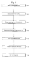
- Figure 1 shows a first method of the invention
- Figures 2 and 3 show a first embodiment of apparatus for carrying out the first method.
- the first method is for matching the flow rate of the first and second fluid flows in respective, fluidly-unconnected first and second flow paths 10 and 12 (shown by flow arrows in Figure 3 and also called fluid flow paths), wherein the first flow path 10 includes a first flow source 14 which includes a positive displacement pump 16, and wherein the second flow path 12 includes a second flow source 18 and a flow-rate transducer 20.
- the first method includes steps a) through g).
- Step a) is labeled as "Shut Off Second Source” in block 22 of Figure 1.
- Step a) includes shutting off the second flow source 18.
- the second flow source is powered down.
- a closed valve is used to isolate the second flow source.
- Step b) is labeled as "Interconnect Flow Paths" in block 26 of Figure 1.
- Step b) includes fluidly interconnecting the first and second flow paths creating an interconnected flow path 24 (shown by flow arrows in Figure 2) which allows substantially the same flow from the positive displacement pump 16 of the first flow source 14 to encounter the flow-rate transducer 20.
- steps a) and b) as shown in Figure 2, the first and second valves 28 and 30 are fully shut and the interconnection valve 32 is fully open.
- Step c) is labeled as "Obtain Readings From Transducer" in block 34 of Figure 1.
- Step c) includes, after steps a) and b), obtaining readings from the flow-rate transducer 20 for various values of the pump speed.
- the value of the pump speed is the value of the pump speed setting of the positive displacement pump 16, as can be appreciated by the artisan.
- the pump speed of the positive displacement pump 16 in Figure 2 is incrementally changed, by incrementally changing the pump speed setting, to create the various values of the pump speed, and the flow is allowed to reach steady state before the transducer readings are taken.
- Other implementations of step c) are left to the artisan.
- step c) includes storing the various values of the pump speed of the positive displacement pump 16 and the corresponding transducer readings of the flow-rate transducer 20 in a map file in a computer 42 with the computer generating the various values of the pump speed and with the flow-rate transducer 20 sending its reading to the computer through signal 46.
- the map file is a two column file, wherein the first column is the various values of the pump speed, wherein the second column is the readings of the flow-rate transducer 20, and wherein the flow-rate transducer reading in a row is the corresponding transducer reading which corresponds to the value of the pump speed in the same row of the map file.
- the computer 42 incrementally changes the pump speed of the positive displacement pump 16 through signal 56. Other implementations of step c) are left to the artisan.
- Step d) is labeled as "Disconnect Flow Path Interconnection" in block 48 of Figure 1.
- Step d) includes, after step c), disconnecting the fluid interconnection between the first and second flow paths.
- Step e) is labeled as "Turn On Second Source” in block 50 of Figure 1.
- Step e) includes turning on the second flow source 18.
- the second flow source is powered up.
- an open valve is used to provide fluid access to the second flow source.
- steps d) and e) as shown in Figure 3, the first and second valves 28 and 30 are fully open and the interconnection valve 32 is fully shut.
- Step f) is labeled as "Obtain Transducer Reading” in block 52 of Figure 1.
- Step f) includes, after steps d) and e), obtaining a reading from the flow-rate transducer 20.
- Step g) is labeled as "Control Flow Rate” in block 54 of Figure 1.
- Step g) includes controlling the flow rate of the first fluid flow to match the flow rate of the second fluid flow by controlling the pump speed using the value of the pump speed in step c) which corresponds to the reading of the flow rate transducer 20 in step c) which substantially matches the reading of the flow-rate transducer 20 in step f).
- step c) values and readings are understood to include interpolated and/or extrapolated values and readings.
- step g) assume one row of the map file, of the previously described application of step c), has "10" as the value of the pump speed and has "25” as the value of the flow-rate transducer reading.
- step f) reading of the flow rate transducer 20 is "25".
- the computer 42 looks in the map file for a "25” reading of the flow rate transducer to obtain the value of "10" from the same row of the map file for the pump speed.
- the computer 42 sends a value of "10" as the pump speed setting to the positive displacement pump 16 through signal 58 to match the flow rate of the first fluid flow to the flow rate of the second fluid flow, as can be appreciated by those skilled in the art.
- step g) are left to the artisan.
- the flow-rate transducer 20 is an uncalibrated flow-rate transducer. It is noted that a flow-rate transducer measures the flow rate of a fluid flow if it directly or indirectly measures the flow rate. In one variation, the flow-rate transducer 20 is an uncalibrated differential pressure transducer. Other examples of flow-rate transducers are left to the artisan.
- the positive displacement pump 16 is an uncalibrated positive displacement pump. In one variation, the positive displacement pump 16 is an uncalibrated peristaltic pump. Other examples of positive displacement pumps are left to the artisan.
- the first flow path 10 is a replacement water flow path of a kidney dialysis machine
- the second flow path 12 is a waste water flow path of the kidney dialysis machine
- the first flow container 60 represents the joining of the first fluid flow (here the replacement water stream) and the thickened blood stream (not shown) for return to the patient (not shown)
- the second flow container 62 represents a waste container.
- the first flow source 14 also includes a reservoir 64, and the positive displacement pump 16 draws fluid from the reservoir 64.
- Other applications are left to the artisan.
- a fluid flow-rate matching system 70 includes a first fluid flow path 10, a second fluid flow path 12, a fluid interconnection path 72, and data.
- the first fluid flow path 10 has in series a first flow source 14 and a first valve 28, wherein the first flow source 14 includes a positive displacement pump 16 having a controllable pump speed.
- the second fluid flow path 12 has in series a second valve 30 and a flow-rate transducer 20.
- the fluid interconnection path 72 has in series a first end 76, an interconnection valve 32, and a second end 78.
- the first end 76 is in fluid communication with the first fluid flow path 10 between the first valve 28 and the positive displacement pump 16 and the second end 78 is in fluid communication with the second fluid flow path 12 between the second valve 30 and the flow-rate transducer 20.
- the data represent various values of the pump speed of the positive displacement pump 16 and represent readings of the flow-rate transducer 20 corresponding to the values of the pump speed taken with the first valve 28 fully shut, the interconnection valve 32 fully open, and the second valve 30 fully shut.
- the pump speed of the positive displacement pump 16 is controlled from the reading of the flow-rate transducer 20 taken with the first valve 28 fully open, the interconnection valve 32 fully shut, and the second valve 30 fully open and from the data.
- the data are stored in a computer 42.
Landscapes
- Engineering & Computer Science (AREA)
- Mechanical Engineering (AREA)
- General Engineering & Computer Science (AREA)
- External Artificial Organs (AREA)
Abstract
Description
Claims (20)
- A method for matching the flow rate of first and second fluid flows in respective, fluidly-unconnected first and second flow paths (10 and 12), wherein the first flow path (10) includes a first flow source (14) which includes a positive displacement pump (16) having a controllable pump speed, wherein the second flow path (12) includes a second flow source (18) and a flow-rate transducer (20), and wherein the method comprises the steps of:a) shutting off the second flow source;b) fluidly interconnecting the first and second flow paths creating an interconnected flow path (24) which allows substantially the same flow from the positive displacement pump of the first flow source to encounter the flow-rate transducer;c) after steps a) and b), obtaining readings from the flow-rate transducer for various values of the pump speed;d) after step c), disconnecting the fluid interconnection between the first and second flow paths;e) turning on the second flow source;f) after steps d) and e), obtaining a reading from the flow-rate transducer; andg) controlling the flow rate of the first fluid flow to match the flow rate of the second fluid flow by controlling the pump speed using the value of the pump speed in step c) which corresponds to the reading of the flow-rate transducer in step c) which substantially matches the reading of the flow-rate transducer in step f).
- The method of claim 1, wherein the flow-rate transducer is an uncalibrated flow-rate transducer.
- The method of claim 2, wherein the flow-rate transducer is an uncalibrated differential pressure transducer.
- The method of claim 2, wherein the positive displacement pump is an uncalibrated positive displacement pump.
- The method of claim 4, wherein the positive displacement pump is an uncalibrated peristaltic pump.
- The method of claim 4, wherein the flow-rate transducer is an uncalibrated flow-rate transducer.
- The method of claim 6, wherein the flow-rate transducer is an uncalibrated differential pressure transducer.
- The method of claim 7, wherein the positive displacement pump is an uncalibrated peristaltic pump.
- The method of claim 8, wherein the first flow path is a water replacement flow path of a kidney dialysis machine, and wherein the second flow path is a waste water flow path of the kidney dialysis machine.
- The method of claim 1, wherein the first flow path is a water replacement flow path of a kidney dialysis machine, and wherein the second flow path is a waste water flow path of the kidney dialysis machine.
- A fluid flow-rate matching system (70) comprising:a) a first fluid flow path (10) having in series a first flow source (14) and a first valve (28), wherein the first flow source includes a positive displacement pump (16) having a controllable pump speed;b) a second fluid flow path (12) having in series a second valve (30) and a flow-rate transducer (20);c) a fluid interconnection path (72) having in series a first end (76), an interconnection valve (32), and a second end (78), wherein the first end is in fluid communication with the first fluid flow path between the first valve and the positive displacement pump, and wherein the second end is in fluid communication with the second fluid flow path between the second valve and the flow-rate transducer; andd) data representing various values of the pump speed of the positive displacement pump and representing readings of the flow-rate transducer corresponding to the values of the pump speed taken with the first valve fully shut, the interconnection valve fully open, and the second valve fully shut, wherein the pump speed is controlled from the reading of the flow-rate transducer taken with the first valve fully open, the interconnection valve fully shut, and the second valve fully open and from the data.
- The method of claim 11, wherein the flow-rate transducer is an uncalibrated flow-rate transducer.
- The method of claim 12, wherein the flow-rate transducer is an uncalibrated differential pressure transducer.
- The method of claim 12, wherein the positive displacement pump is an uncalibrated positive displacement pump.
- The method of claim 14, wherein the positive displacement pump is an uncalibrated peristaltic pump.
- The method of claim 14, wherein the flow-rate transducer is an uncalibrated flow-rate transducer.
- The method of claim 16, wherein the flow-rate transducer is an uncalibrated differential pressure transducer.
- The method of claim 17, wherein the positive displacement pump is an uncalibrated peristaltic pump.
- The method of claim 18, wherein the first flow path is a water replacement flow path of a kidney dialysis machine, and wherein the second flow path is a waste water flow path of the kidney dialysis machine.
- The method of claim 11, wherein the first flow path is a water replacement flow path of a kidney dialysis machine, and wherein the second flow path is a waste water flow path of the kidney dialysis machine.
Applications Claiming Priority (2)
| Application Number | Priority Date | Filing Date | Title |
|---|---|---|---|
| US45700 | 2002-01-11 | ||
| US10/045,700 US6746606B2 (en) | 2002-01-11 | 2002-01-11 | Method and system for matching flow rate |
Publications (3)
| Publication Number | Publication Date |
|---|---|
| EP1327777A2 true EP1327777A2 (en) | 2003-07-16 |
| EP1327777A3 EP1327777A3 (en) | 2003-12-03 |
| EP1327777B1 EP1327777B1 (en) | 2009-09-16 |
Family
ID=21939394
Family Applications (1)
| Application Number | Title | Priority Date | Filing Date |
|---|---|---|---|
| EP02080606A Expired - Lifetime EP1327777B1 (en) | 2002-01-11 | 2002-12-30 | Method and system for matching flow rate |
Country Status (3)
| Country | Link |
|---|---|
| US (1) | US6746606B2 (en) |
| EP (1) | EP1327777B1 (en) |
| DE (1) | DE60233711D1 (en) |
Families Citing this family (13)
| Publication number | Priority date | Publication date | Assignee | Title |
|---|---|---|---|---|
| US7241272B2 (en) | 2001-11-13 | 2007-07-10 | Baxter International Inc. | Method and composition for removing uremic toxins in dialysis processes |
| ATE505223T1 (en) | 2002-07-19 | 2011-04-15 | Baxter Int | SYSTEM FOR PERITONEAL DIALYSIS |
| ITTO20040092A1 (en) * | 2003-03-31 | 2004-05-18 | Hitachi Kokico Ltd | AIR COMPRESSOR AND METHOD FOR ITS CONTROL |
| US8029454B2 (en) | 2003-11-05 | 2011-10-04 | Baxter International Inc. | High convection home hemodialysis/hemofiltration and sorbent system |
| JP4801040B2 (en) | 2004-03-05 | 2011-10-26 | ウオーターズ・テクノロジーズ・コーポレイシヨン | Optimization of pressure monitoring device using fluid passage |
| US8114276B2 (en) | 2007-10-24 | 2012-02-14 | Baxter International Inc. | Personal hemodialysis system |
| US9415150B2 (en) | 2007-11-09 | 2016-08-16 | Baxter Healthcare S.A. | Balanced flow dialysis machine |
| US8449500B2 (en) * | 2007-11-16 | 2013-05-28 | Baxter International Inc. | Flow pulsatility dampening devices for closed-loop controlled infusion systems |
| US8652082B2 (en) * | 2008-04-15 | 2014-02-18 | Gambro Lundia Ab | Blood treatment apparatus |
| US10265454B2 (en) * | 2008-07-25 | 2019-04-23 | Baxter International Inc. | Dialysis system with flow regulation device |
| ES2403598T5 (en) * | 2009-12-22 | 2016-12-13 | Gambro Lundia Ab | Method and apparatus for controlling a fluid flow rate in a fluid transport conduit of a medical device |
| US8366667B2 (en) | 2010-02-11 | 2013-02-05 | Baxter International Inc. | Flow pulsatility dampening devices |
| US10655455B2 (en) * | 2016-09-20 | 2020-05-19 | Cameron International Corporation | Fluid analysis monitoring system |
Family Cites Families (12)
| Publication number | Priority date | Publication date | Assignee | Title |
|---|---|---|---|---|
| US4370983A (en) * | 1971-01-20 | 1983-02-01 | Lichtenstein Eric Stefan | Computer-control medical care system |
| US3882861A (en) | 1973-09-24 | 1975-05-13 | Vital Assists | Auxiliary control for a blood pump |
| US4021341A (en) * | 1974-02-19 | 1977-05-03 | Cosentino Louis C | Hemodialysis ultrafiltration system |
| US4334988A (en) | 1975-12-30 | 1982-06-15 | Hospal Medical Corp. | Control of dialysis and ultrafiltration |
| SE401894B (en) | 1976-10-14 | 1978-06-05 | Gambro Ab | DIALYSIS SYSTEM |
| GB1537444A (en) * | 1977-06-28 | 1978-12-29 | Nycotron As | Apparatus for regulating and monitoring dialysis of blood in a dialyzer |
| FR2651037B1 (en) * | 1989-08-16 | 1991-10-25 | Hospal Ind | METHOD FOR CALIBRATING A PULSE RESPONSE FLOWMETER |
| US5455781A (en) * | 1993-08-31 | 1995-10-03 | Dresser Industries, Inc. | Apparatus and method for determining the measurement accuracy of electronic gas meters |
| DE19700466A1 (en) * | 1997-01-09 | 1998-07-16 | Polaschegg Hans Dietrich Dr | Hemodiafiltration device and method |
| US5975353A (en) * | 1997-11-21 | 1999-11-02 | Dresser Industries, Inc. | Fluid system and method utilizing a master and blend ratio meter |
| US6607669B2 (en) * | 2000-06-23 | 2003-08-19 | Scilog, Inc. | Method and apparatus for enhancing filtration yields in tangential flow filtration |
| US6610027B1 (en) * | 2000-08-17 | 2003-08-26 | Mohamed Kaled Mohamed El Hatu | Hemodialysis |
-
2002
- 2002-01-11 US US10/045,700 patent/US6746606B2/en not_active Expired - Fee Related
- 2002-12-30 DE DE60233711T patent/DE60233711D1/en not_active Expired - Lifetime
- 2002-12-30 EP EP02080606A patent/EP1327777B1/en not_active Expired - Lifetime
Also Published As
| Publication number | Publication date |
|---|---|
| DE60233711D1 (en) | 2009-10-29 |
| US20030132161A1 (en) | 2003-07-17 |
| EP1327777A3 (en) | 2003-12-03 |
| EP1327777B1 (en) | 2009-09-16 |
| US6746606B2 (en) | 2004-06-08 |
Similar Documents
| Publication | Publication Date | Title |
|---|---|---|
| EP1327777B1 (en) | Method and system for matching flow rate | |
| US6752928B2 (en) | Flow matching method and system using two transducers | |
| RU2321880C2 (en) | Flow speed measuring module and respective measuring method | |
| US8684705B2 (en) | Method and system for controlling operation of a pump based on filter information in a filter information tag | |
| AU2007202214B2 (en) | Surgical system having integral pneumatic manifolds | |
| US6890157B2 (en) | Matching or not matching flow rates in two fluidly-unconnected flow paths | |
| WO2002090771A3 (en) | A liquid pumping system | |
| AU2003249296A1 (en) | Systems and methods for performing peritoneal dialysis | |
| MXPA03000328A (en) | Apparatus and method for regulating fluid pump pressures. | |
| WO2008106538A8 (en) | Cassette system integrated apparatus | |
| DE502005002817D1 (en) | Hydrodynamic coupling device | |
| CN104895642B (en) | Control system for pilot solenoid valve single-chamber feedback variable-displacement vane pump | |
| WO2020005707A3 (en) | Fluid integrating system for producing an integrated fluid according to consumer-defined preferences | |
| CN113959106B (en) | Method and device for controlling refrigerant circulation system and refrigerant circulation system | |
| US6206644B1 (en) | Compact dual pump | |
| TW200801335A (en) | Fluid pressure drive device | |
| US20230060393A1 (en) | Electronic control unit, hydraulic system, and method for controlling a hydraulic system | |
| CN105351188B (en) | A kind of two grades of variable displacement vane pump control systems of combination valve type | |
| CN114060356B (en) | Four-valve-core valve port independent control valve flow measuring method and system | |
| CN106872340A (en) | A kind of liquid fluid system for FCM analysis | |
| EP1394416A3 (en) | Dual discharge hydraulic pump and system therefor | |
| JP2023505328A5 (en) | ||
| CN117917760A (en) | Treatment liquid supply system and operation method thereof | |
| CN206546318U (en) | A kind of liquid fluid system for FCM analysis | |
| US20250367031A1 (en) | Ophthalmic surgical system and method for operating the ophthalmic surgical system |
Legal Events
| Date | Code | Title | Description |
|---|---|---|---|
| PUAI | Public reference made under article 153(3) epc to a published international application that has entered the european phase |
Free format text: ORIGINAL CODE: 0009012 |
|
| AK | Designated contracting states |
Designated state(s): AT BE BG CH CY CZ DE DK EE ES FI FR GB GR IE IT LI LU MC NL PT SE SI SK TR |
|
| AX | Request for extension of the european patent |
Extension state: AL LT LV MK RO |
|
| PUAL | Search report despatched |
Free format text: ORIGINAL CODE: 0009013 |
|
| AK | Designated contracting states |
Kind code of ref document: A3 Designated state(s): AT BE BG CH CY CZ DE DK EE ES FI FR GB GR IE IT LI LU MC NL PT SE SI SK TR |
|
| AX | Request for extension of the european patent |
Extension state: AL LT LV MK RO |
|
| 17P | Request for examination filed |
Effective date: 20040603 |
|
| AKX | Designation fees paid |
Designated state(s): DE FR GB IT |
|
| GRAP | Despatch of communication of intention to grant a patent |
Free format text: ORIGINAL CODE: EPIDOSNIGR1 |
|
| GRAS | Grant fee paid |
Free format text: ORIGINAL CODE: EPIDOSNIGR3 |
|
| GRAA | (expected) grant |
Free format text: ORIGINAL CODE: 0009210 |
|
| AK | Designated contracting states |
Kind code of ref document: B1 Designated state(s): DE FR GB IT |
|
| REG | Reference to a national code |
Ref country code: GB Ref legal event code: FG4D |
|
| REF | Corresponds to: |
Ref document number: 60233711 Country of ref document: DE Date of ref document: 20091029 Kind code of ref document: P |
|
| PLBE | No opposition filed within time limit |
Free format text: ORIGINAL CODE: 0009261 |
|
| STAA | Information on the status of an ep patent application or granted ep patent |
Free format text: STATUS: NO OPPOSITION FILED WITHIN TIME LIMIT |
|
| 26N | No opposition filed |
Effective date: 20100617 |
|
| PGFP | Annual fee paid to national office [announced via postgrant information from national office to epo] |
Ref country code: FR Payment date: 20101224 Year of fee payment: 9 |
|
| PG25 | Lapsed in a contracting state [announced via postgrant information from national office to epo] |
Ref country code: IT Free format text: LAPSE BECAUSE OF FAILURE TO SUBMIT A TRANSLATION OF THE DESCRIPTION OR TO PAY THE FEE WITHIN THE PRESCRIBED TIME-LIMIT Effective date: 20090916 |
|
| PGFP | Annual fee paid to national office [announced via postgrant information from national office to epo] |
Ref country code: GB Payment date: 20101229 Year of fee payment: 9 |
|
| PGFP | Annual fee paid to national office [announced via postgrant information from national office to epo] |
Ref country code: DE Payment date: 20101222 Year of fee payment: 9 |
|
| GBPC | Gb: european patent ceased through non-payment of renewal fee |
Effective date: 20111230 |
|
| REG | Reference to a national code |
Ref country code: FR Ref legal event code: ST Effective date: 20120831 |
|
| REG | Reference to a national code |
Ref country code: DE Ref legal event code: R119 Ref document number: 60233711 Country of ref document: DE Effective date: 20120703 |
|
| PG25 | Lapsed in a contracting state [announced via postgrant information from national office to epo] |
Ref country code: GB Free format text: LAPSE BECAUSE OF NON-PAYMENT OF DUE FEES Effective date: 20111230 Ref country code: DE Free format text: LAPSE BECAUSE OF NON-PAYMENT OF DUE FEES Effective date: 20120703 |
|
| PG25 | Lapsed in a contracting state [announced via postgrant information from national office to epo] |
Ref country code: FR Free format text: LAPSE BECAUSE OF NON-PAYMENT OF DUE FEES Effective date: 20120102 |