EP1327764A2 - Fuel injection system - Google Patents
Fuel injection system Download PDFInfo
- Publication number
- EP1327764A2 EP1327764A2 EP03000801A EP03000801A EP1327764A2 EP 1327764 A2 EP1327764 A2 EP 1327764A2 EP 03000801 A EP03000801 A EP 03000801A EP 03000801 A EP03000801 A EP 03000801A EP 1327764 A2 EP1327764 A2 EP 1327764A2
- Authority
- EP
- European Patent Office
- Prior art keywords
- engine
- fuel
- injection
- revolution speed
- cylinders
- Prior art date
- Legal status (The legal status is an assumption and is not a legal conclusion. Google has not performed a legal analysis and makes no representation as to the accuracy of the status listed.)
- Granted
Links
Images


Classifications
-
- F—MECHANICAL ENGINEERING; LIGHTING; HEATING; WEAPONS; BLASTING
- F02—COMBUSTION ENGINES; HOT-GAS OR COMBUSTION-PRODUCT ENGINE PLANTS
- F02D—CONTROLLING COMBUSTION ENGINES
- F02D41/00—Electrical control of supply of combustible mixture or its constituents
- F02D41/008—Controlling each cylinder individually
- F02D41/0085—Balancing of cylinder outputs, e.g. speed, torque or air-fuel ratio
-
- F—MECHANICAL ENGINEERING; LIGHTING; HEATING; WEAPONS; BLASTING
- F02—COMBUSTION ENGINES; HOT-GAS OR COMBUSTION-PRODUCT ENGINE PLANTS
- F02D—CONTROLLING COMBUSTION ENGINES
- F02D41/00—Electrical control of supply of combustible mixture or its constituents
- F02D41/24—Electrical control of supply of combustible mixture or its constituents characterised by the use of digital means
- F02D41/2406—Electrical control of supply of combustible mixture or its constituents characterised by the use of digital means using essentially read only memories
- F02D41/2425—Particular ways of programming the data
- F02D41/2429—Methods of calibrating or learning
- F02D41/2441—Methods of calibrating or learning characterised by the learning conditions
- F02D41/2448—Prohibition of learning
-
- F—MECHANICAL ENGINEERING; LIGHTING; HEATING; WEAPONS; BLASTING
- F02—COMBUSTION ENGINES; HOT-GAS OR COMBUSTION-PRODUCT ENGINE PLANTS
- F02D—CONTROLLING COMBUSTION ENGINES
- F02D41/00—Electrical control of supply of combustible mixture or its constituents
- F02D41/24—Electrical control of supply of combustible mixture or its constituents characterised by the use of digital means
- F02D41/2406—Electrical control of supply of combustible mixture or its constituents characterised by the use of digital means using essentially read only memories
- F02D41/2425—Particular ways of programming the data
- F02D41/2429—Methods of calibrating or learning
- F02D41/2451—Methods of calibrating or learning characterised by what is learned or calibrated
- F02D41/2454—Learning of the air-fuel ratio control
-
- F—MECHANICAL ENGINEERING; LIGHTING; HEATING; WEAPONS; BLASTING
- F02—COMBUSTION ENGINES; HOT-GAS OR COMBUSTION-PRODUCT ENGINE PLANTS
- F02D—CONTROLLING COMBUSTION ENGINES
- F02D2200/00—Input parameters for engine control
- F02D2200/02—Input parameters for engine control the parameters being related to the engine
- F02D2200/06—Fuel or fuel supply system parameters
- F02D2200/0606—Fuel temperature
-
- F—MECHANICAL ENGINEERING; LIGHTING; HEATING; WEAPONS; BLASTING
- F02—COMBUSTION ENGINES; HOT-GAS OR COMBUSTION-PRODUCT ENGINE PLANTS
- F02D—CONTROLLING COMBUSTION ENGINES
- F02D2200/00—Input parameters for engine control
- F02D2200/02—Input parameters for engine control the parameters being related to the engine
- F02D2200/10—Parameters related to the engine output, e.g. engine torque or engine speed
- F02D2200/1015—Engines misfires
Definitions
- the present invention relates to a fuel injection system for an internal combustion engine.
- engine a multi-cylinder type diesel engine
- engine vibration due to an engine revolution speed change in each combustion stroke in each cylinder which is caused by variations in combustion power between the cylinders.
- vibration and noise of the engine may offend a driver.
- an engine revolution speed change between cylinders in the engine occurs due to variations in fuel injection amount and combustion factor in the engine between cylinders which are caused by a difference between individual injectors for cylinders.
- a non-uniform fuel amount compensating control In view of this point and for the purpose of diminishing an engine revolution speed change between cylinders to decrease engine vibration in the whole of the engine there has been conducted a non-uniform fuel amount compensating control.
- the non-uniform fuel amount compensating control an engine revolution speed change in each combustion stroke in each of the engine cylinders is detected and the fuel injection amount is adjusted to an optimum injection amount for each of the cylinders so as to smooth the engine revolution speed change between the cylinders.
- the non-uniform fuel amount compensating control when a cylinder-by-cylinder injection correction amount updating (reflecting) condition is existent, an engine revolution speed change in each combustion stroke in each engine cylinder is detected and the detected value is compared with a mean value of engine revolution speed changes in all the cylinders, then the injection correction amount for each cylinder is updated so as to smooth the engine revolution speed change between the cylinders.
- the updated value of the injection correction amount is stored to compensate the fuel injection amount for each of the engine cylinders.
- This control is also called as a FCCB learning control or a FCCB control and the cylinder-by-cylinder injection correction amount updating condition is also called as a FCCB condition.
- an engine revolution speed change in each cylinder is detected based on both a maximum engine revolution speed and a minimum engine revolution speed in each combustion stroke in each cylinder. Subsequently, a deviation of the engine revolution speed change in each cylinder is calculated based on both the detected value of the engine revolution speed change in each cylinder and a mean value of engine revolution speed changes in all cylinders.
- an injection correction amount for each cylinder is updated so as to smooth the engine revolution speed change between cylinders.
- Two temperature conditions which are an engine temperature detected by an engine temperature detecting means and a fuel temperature detected by a fuel temperature detecting means are inputted.
- the injection correction amount for each cylinder updated by a correction amount updating means is stored in a correction amount storage means as an injection correction amount for each cylinder corresponding to the two temperature conditions.
- an initial injection correction amount for each cylinder is calculated based on the injection correction amount for each cylinder stored in the storage means in accordance with the two temperature conditions.
- the initial injection correction amount is obtained based on present values of the engine temperature and the fuel temperature.
- the FCCB control can be resumed on the basis of the initial injection correction amount for each cylinder. Since the initial injection correction amount has been stored in accordance with the temperature condition, it is possible to suppress engine vibration and noise of the engine.
- the FCCB control for smoothing the engine revolution speed may be performed when the engine revolution speed is a predetermined value or less.
- the FCCB control may be performed in an idling condition of the engine.
- the FCCB control may be performed when the vehicle running speed is a predetermined value or less.
- the storage means may storage initial values that are set in a manufacturing process.
- the initial injection correction amount may be obtained in several situations that meets the condition in which the FCCB condition was not existent last time but is existent this time.
- the initial injection correction amount may be obtained when the FCCB condition is established for the first time after start-up of the engine.
- the initial injection correction amount may be obtained when the FCCB condition is established just after the engine has stared under cold condition after the engine has stopped under completely warmed-up condition.
- the initial injection correction amount may be obtained when the FCCB condition is established after the vehicle has traveled just after the engine has started under a cold condition.
- Figs. 1 to 7 illustrate an embodiment of the present invention.
- Fig. 1 illustrates an entire construction of a common rail type fuel injection system applied with the present invention.
- Fig. 2 illustrates a schematic construction of an injection amount control unit in the common rail type fuel injection system.
- the fuel injection system is an electronic controlled fuel injection system for multi-cylinder diesel engine.
- the system has a plurality of fuel injectors 1-4 mounted on respective cylinders of the multi-cylinder diesel engine.
- the embodiment shows a four-cylinder engine.
- the system has a common rail 5 serving as an accumulator vessel for accumulating fuel pressurized in high pressure corresponding to a fuel injection pressure.
- the system has a supply pump 7 of a variable delivery type which pressurizes fuel pumped up from a fuel tank 6.
- the supply pump 7 discharges pressurized fuel into the common rail 5.
- the system has an electronic control unit (ECU) 10 which controls the injectors 1-4 and the supply pump 7 electronically.
- ECU electronice control unit
- the injectors 1-4 are connected respectively to high-pressure pipes 8.
- the high-pressure 8 are branch pipes branching from the common rail 5.
- the injectors 1-4 inject the high-pressure fuel accumulated in the common rail 5 into combustion chambers in the engine cylinders.
- the injectors 1-4 are electromagnetic fuel injection valves.
- Each of the injectors is constituted with a fuel injection nozzle, a needle, and an operating mechanism for the needle.
- the nozzle has at least one of injection hole and has a valve seat.
- the needle is housed in the nozzle and movable in axial direction to open and close the injection hole.
- the needle is a valve element cooperates with the valve seat.
- the operating mechanism operates the needle in axial direction.
- the operating mechanism has pressure chambers for obtaining fuel pressure onto the needle, a resilient urging means and an electromagnetic valve.
- the resilient urging means may be provided by a spring that urges the nozzle needle in a valve closing direction.
- the electromagnetic valve controls a pressure in the chambers so as to operate the needle in opening direction.
- Fig. 1, 11, 12, 13 and 14 denote the electromagnetic valves.
- the electromagnetic valve serves as an actuator for controlling the injector.
- An amount of fuel to be injected into the combustion chambers and a timing of the injection can be adjusted by controlling ON and OFF of the electromagnetic valves 11-14 via the ECU 10.
- the electromagnetic valves 11-14 and the ECU 10 work as means for changing injection period. More specifically, while the electromagnetic valve is open, the pressure in back pressure control chamber for the needle is withdrawn and the needle lifts from respective valve seat, whereby the high-pressure fuel accumulated within the common rail 5 is injected from the nozzle hole of the nozzle into the combustion chamber.
- the shorter the injection period from valve opening to valve closing of the injector is, the smaller the amount of fuel injected into the combustion chamber.
- the common rail 5 is connected through a fuel pipe 18 to a discharge port of the supply pump 7.
- the common rail 5, the pipes 8, and the pipe 18 are high-pressure fuel passages. Fuel leaking from the injectors 1-4 and fuel leaking from the supply pump 7 are returned to the fuel tank 6 through return pipes 9.
- the return pipes 9 are so called as leak pipes, relief pipes, or low-pressure fuel passages.
- a pressure limiter 15 is attached to a return pipe 9 which is for the relief of fuel from the common rail 5 to the fuel tank 6.
- the pressure limiter 15 releases fuel from the common rail 5 so as to limit the fuel pressure in the common rail 5 below an upper limit pressure.
- the upper limit pressure is preset in accordance with pressure resistant of components.
- the supply pump 7 is constituted as a high-pressure feed pump.
- the supply pump 7 includes a high-pressure pump section and a feed pump that is a low-pressure feed pump for introducing fuel from the fuel tank 6 via a fuel pipe 17 and a fuel filter 16.
- the supply pump 7 has a pump drive shaft being adapted to rotate with rotation of an engine crankshaft.
- the pump drive shaft drives the high-pressure pump section and the feed pump.
- the fuel introduced by the feed pump is supplied to the high-pressure pump section.
- the high-pressure pump section pressurizes fuel and discharges the pressurized fuel into the common rail 5 via a discharge port and the fuel pipe 18.
- An electromagnetic valve 19 as an actuator is attached to the supply pump 7.
- the electromagnetic valve 19 is a fuel injection pressure changing means which is controlled electronically with a control signal provided from ECU 10.
- the electromagnetic valve 19 adjusts the amount of fuel supplied from the supply pump 7 to the common rail 5, thereby changing the injection pressure of fuel to be injected from the injectors 1-4.
- the electromagnetic valve 19 may be a suction control valve that is disposed between the feed pump and the high-pressure pump section and controls amount of fuel introduced into the high-pressure pump section.
- the ECU 10 corresponds to all of the following means defined in the present invention.
- the ECU 10 provides means for detecting engine revolution speed, means for calculating engine revolution speed change, means for updating correction amount, and means for calculating initial correction amount.
- the ECU 10 includes a microcomputer for performing a control device.
- the ECU 10 includes a CPU which carries out control processing and arithmetic processings, memories such as RAM, ROM for the storage of various control programs and data and stand-by RAM, input circuit, output circuit, power supply circuit, and injector drive circuit (EDU) 20.
- the memories works as correction amount storage means for storing correction amount.
- the EDU 20 used in this embodiment is constructed so that upon receipt of a control signal from ECU 10 controls the state of current flow to the electromagnetic valves 11-14 in the injectors 1-4 so as to open or close the valves in accordance with injection timing and fuel injection amount both calculated by the ECU 10.
- the system has the following sensors connected to an input side of the ECU 10 so as to input engine parameters indicative of engine operating conditions.
- a cylinder identifying sensor 21 detects a rotational angle of a cam shaft in the engine to identify a cylinder for fuel injection and outputs a signal G.
- a crank angle sensor 22 detects a rotational angle of an engine crankshaft and outputs a signal NE.
- An accelerator position sensor detects a depression amount of an accelerator pedal, accelerator position and outputs a signal ACCP.
- a cooling water temperature sensor 24 detects the temperature of engine cooling water and outputs a signal thw. The cooling water temperature sensor 24 is means for detecting engine temperature.
- a fuel temperature sensor 25 detects the temperature of fuel sucked into the supply pump 7 and outputs a signal thf.
- a common rail pressure sensor 26 detects a fuel pressure in the common rail 5 and outputs a signal Pc.
- the cylinder identifying sensor 21 has a signal rotor and a pickup.
- the signal rotor rotates correspondingly to an engine camshaft.
- the signal rotor has convex teeth correspondingly to reference crank angle indicative of reference stroke of the cylinders.
- the pickup may be an electromagnetic pickup or magnetic sensor such as Hall effect device.
- the pickup generates the signal G characterized by pulses corresponding to the convex teeth.
- One of the convex teeth is formed in a different profile for indicating a specific cylinder such as the first cylinder of the engine.
- one of the teeth corresponding to the first cylinder is wider in the rotation direction than the other convex teeth or comprises plural convex teeth.
- a reference cylinder pulse G1 of the signal G is provided longer than the interval during which the signal NE is generated twice, while other pulse G2, G3, G4 of the signal G are provided shorter than the twice-generation interval of the signal NE.
- the cylinder identifying sensor 21 outputs such a waveform signal as shown in Figs. 3A or 3B. That is, a wide pulse G1 of the signal G or plural pulses G1 of the signal G are outputted upon arrival of the first piston in the first cylinder at a position just before fuel injection.
- a narrow pulse G3 of the signal G is outputted upon arrival of a third piston in a third cylinder at a position just before fuel injection
- a narrow pulse G4 of the signal G is outputted upon arrival of a fourth piston in a fourth cylinder at a position just before fuel injection
- a narrow pulse G2 of the signal G is outputted upon arrival of a second piston in a second cylinder at a position just before fuel injection.
- the crank angle sensor 22 includes a signal rotor and a pickup.
- the signal rotor is adapted to rotate once while the crankshaft rotates once.
- the signal rotor has convex teeth for crank angle detection formed in a large number.
- the pickup generates the signal NE.
- the signal rotor is formed with an untoothed portion, one convex tooth-free portion, at a position just after generation of the reference cylinder pulse of the signal G to generate an untoothed signal D with a large width.
- This untoothed portion is also formed at a 180° opposed position so that the untoothed signal is generated just after generation of the reference cylinder pulse of the signal G for detecting the first piston in the first cylinder and also just after generation of the pulse of the signal G for detecting the fourth piston in the fourth cylinder.
- the crank angle sensor 22 outputs such a waveform signal as shown in Fig. 3A or 3B. That is, the signal NE of a small width, which are continuous at a predetermined angle, are outputted repeatedly with the exception that the untoothed pulse D is generated.
- the ECU 10 used in this embodiment detects the engine revolution speed NE, engine speed, by measuring an interval time between the pulses of the signal NE.
- the ECU 10 calculates an injection timing of each of the injectors 1-4 and a discharge amount of the supply pump 7 on the basis of the inputted signals.
- the ECU 10 adjusts turn on timing and turn off timing of current supply for the electromagnetic valve 19 in the supply pump 7 so as to maintain the fuel injection pressure at an optimum pressure, that is target common rail pressure.
- the ECU 10 calculates a base injection amount q on the basis of operating conditions of the engine, i.e., engine speed NE, accelerator position ACCP, cooling water temperature thw, and fuel temperature thf. Then, the ECU 10 calculates an injection command value, injection pulse width, Tq on the basis of both the base injection amount q and a common rail pressure Pc. The ECU 10 applies a pulse-like injector driving current proportional to the thus-calculated injection command value Tq to the electromagnetic valves 11-14 each independently. The pulse signal supplied for the electromagnetic valves 11-14 are so called as TQ pulses. As a result, the engine is operated.
- the ECU 10 used in this embodiment is constructed so as to execute a non-uniform fuel amount compensating control, the FCCB control.
- the FCCB control the ECU 10 performs a fine adjustment to the injection amounts injected from respective injectors 1-4 so as to smooth the engine speed when the engine is in an idling mode, stable idling state. More specifically, the ECU 10 detects an engine revolution speed change in each combustion stroke in each engine cylinder. Then, the ECU 10 compares the thus-detected value with a target value such as a mean value of engine revolution speed changes in all the cylinders. Finally, the ECU 10 adjusts the fuel injection amount to an optimum value for each cylinder in an independent manner to suppress deviation of the engine speed.
- an instantaneous engine revolution speed in each combustion stroke in each engine cylinder is calculated by calculating an interval time of the signal NE.
- a maximum value of the interval time of the signal NE between BTDC90°CA and ATDC90°CA is sampled and stored as a value indicative of a minimum engine revolution speed N1 of the instantaneous engine revolution speed of the given cylinder.
- a minimum value of the interval time of the signal NE between BTDC90°CA and ATDC90°CA is also sampled and stored as a value indicative of a maximum engine revolution speed Nh of the instantaneous engine revolution speed of the given cylinder.
- a cylinder-by-cylinder revolution difference ⁇ Nk between the maximum revolution Nh and the minimum revolution N1 is calculated in each cylinder.
- the engine revolution speed change in each cylinder are calculated.
- a mean value ⁇ Nk/n of the revolution differences in all the engine cylinders is calculated. That is, the engine revolution speed changes in all the cylinders are averaged to afford a mean value.
- a deviation d ⁇ Nk of the engine revolution speed change in each cylinder is calculated on the basis of the revolution difference ⁇ Nk and the mean value ⁇ Nk/n.
- the fuel injection amount for each cylinder in the engine is corrected so as to smooth the engine revolution speed change between the cylinders in the engine.
- the mean value ⁇ Nk/n may be a target value or a predetermined value may be a target value for correcting the fuel injection amount for smoothing the engine revolution speed.
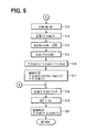
- FIGS. 4 and 5 are flow charts illustrating the injection amount control method.
- the routine shown in Figs. 4 and 5 starts.
- engine parameters are inputted from the sensors. More particularly, the signals G, NE, ACCP, thw, thf and Pc are inputted. Further the engine revolution speed NE is calculated by measuring the interval time of pulses of the signal NE (step S1).
- a base injection amount q and an injection timing T of the injectors 1-4 are calculated based on the inputted signals (step S2).
- the base injection amount q is a target injection amount to be injected into the combustion chamber so as to maintain the engine output in accordance with the engine operating condition. This process works as means for calculating injection amount and/or injection timing.
- step S3 the cylinder in which fuel is to be injected is identified based on the signal G and signal NE.
- the identified cylinder is denoted as k cylinder (step S3). This process works as means for identifying cylinder.
- step S4 a check is made to see if the cylinder-by-cylinder injection correction amount reflecting condition exists (ON) or not (step S4).
- the cylinder-by-cylinder injection correction amount reflecting condition is the FCCB condition. If the answer is negative, that is, if the condition is OFF, it is judged that the driver has shifted the vehicular operation from idling mode to vehicular running, and a FCCB flag xqkcf is turned OFF (step S5).
- the cylinder-by-cylinder injection correction amount ⁇ qk(i) is cleared (step S6). Thereafter, the processing flow advances to step S18.
- the cylinder-by-cylinder injection correction amount ⁇ qk(i) is also called as a FCCB amount or an injection correction amount for the cylinder concerned.
- step S4 If the answer in step S4 is affirmative, that is, a check is made to see if the FCCB condition was existent last time or not by referencing the FCCB flag xqkcf (step S7). If the FCCB flag xqkcf has been already turned on, it is judged whether an updating condition exists (ON) or not. More particularly, it is determined whether or not the engine is in a stable idling state (step S8). For instance, if the engine revolution speed NE is a predetermined value or less, e.g., an idling speed of 850 rpm or so the determination will be YES.
- the engine revolution speed NE is a predetermined value or less, e.g., an idling speed of 850 rpm or so the determination will be YES.
- step S9 the injection correction amount ⁇ qki up to the last time which was stored is read out (step S9).
- a correction coefficient K corresponding to the present engine operating condition is calculated (step S10).
- the cylinder-by-cylinder injection correction amount ⁇ qk(i) is corrected based on the correction coefficient K (step S18).
- the cylinder-by-cylinder injection correction amount ⁇ qk(i) and the correction coefficient K is reflected to a determining process of a final injection amount q in the step S8.
- step S8 If the answer in step S8 is affirmative, that is, if the updating condition is satisfied, the revolution difference ⁇ Nk between a maximum engine revolution speed Nh and a minimum engine revolution speed N1 in each cylinder is calculated.
- the maximum engine revolution speed Nh and the minimum engine revolution speed N1 are sampled and stored corresponding to each cylinder. Those values are indicative of combustion power of given cylinder. That is, a detected value of the engine revolution speed change in each engine cylinder is calculated (step S12). This process is provided as means for detecting engine revolution speed change of each cylinder.
- a mean value ⁇ Nk/n of the revolution differences is calculated, that is, a mean value of engine revolution speed changes in all the engine cylinders is calculated (step S13).
- the mean value can be calculated in every cycle of the engine or every predetermined cycles of the engine.
- a deviation d ⁇ Nk of the engine revolution speed change in each cylinder is calculated from both the detected value ⁇ Nk and the mean value ⁇ Nk/n (step S14). This process is provided as means for calculating an engine revolution speed change of each cylinder.
- the deviation of the other cylinders may be obtained in the same manner.
- an injection correction amount ⁇ qk of this time for the cylinder concerned is calculated from the value calculated in step S14, (step S15).
- the injection correction amount ⁇ qk(i-1) up to the last time for the cylinder concerned and the injection correction amount ⁇ qk of this time for the cylinder concerned are added to update the cylinder-by-cylinder injection correction amount ⁇ qk(i) (step S16). This process is provided as means for updating the injection correction amount.
- the cylinder-by-cylinder injection correction amount ⁇ qk(i) is stored into a storage corresponding to the cylinder concerned (step S17).
- the cylinder-by-cylinder injection correction amount ⁇ qk(i) is stored in a two-dimensional map defined by the water temperature thw and the fuel temperature thf as shown in Fig. 6.
- the map is assembled for each cylinder. This process works as means for storing the correction amount into storage device.
- the ECU 10 stores cylinder-by-cylinder injection correction amount ⁇ qk(i) that reflects temperature conditions of the engine and accumulates such date for entire engine operation condition.
- step S18 the final injection amount q is determined based on the base injection amount q calculated in the step S2, the cylinder-by-cylinder injection correction amount ⁇ qk(i) determined in one of the steps S6, S9, S16 and S21, and the correction coefficient K. Then the final injection amount q in step S18 is converted into an injection amount command value such as a valve opening command value, a valve closing command value, an injection timing T and an injection pulse width Tq. Then the injection amount commend value is set to an output stage (step S19).
- an injection amount command value such as a valve opening command value, a valve closing command value, an injection timing T and an injection pulse width Tq.
- the cylinder-by-cylinder injection correction amount ⁇ qk(i) is stored as the value ⁇ qki (step S20).
- step S7 If the answer in step S7 is NO, that is, if the FCCB flag (xqkcf) is OFF, an initial value of the injection correction amount for the cylinder concerned is calculated from storage data.
- thf(m) is a present value of the fuel temperature
- thw(n) is a present value of the cooling water temperature.
- step S22 the FCCB flag xqkcf is turned ON (step S22). Thereafter, the processing flow advances to the step S18.
- the FCCB condition is OFF
- the engine water temperature (thw) condition is a warm water condition equal to or more than a predetermined value
- the injection correction amount for smoothing the engine revolution speed change between engine cylinders is stored in storage data which is constituted by a two-dimensional map of the engine water temperature thw and the fuel temperature thf as shown in Fig. 6. Then, an initial value of the injection correction amount just after the FCCB condition is established is obtained from the stored data in accordance with the temperature condition of the engine when the FCCB condition is established. The FCCB control is performed on the basis of the initial value obtained by looking up the stored data.
- Fig. 7 shows an operation of the embodiment.
- the engine is started on the left end, then the engine revolution speed NE reaches to a stable idling speed and the FCCB condition is established and turns ON.
- the FCCB condition is maintained ON, the FCCB control is performed to suppress vibration of the engine.
- the driver accelerates the engine from the timing A to the timing B, the FCCB condition is turned off.
- the FCCB condition is established again at the timing B, the temperature condition of the engine has been changed since the FCCB condition is turned off.
- the cooling water temperature has been increased from Tw1 to Tw2.
- the fuel temperature has been increased from Tf1 to Tf2.
- the initial value of the injection correction amount ⁇ qk(i) is obtained in accordance with the temperature Tw2 and Tf2. Therefore, it is possible to obtain a proper level of the injection correction amount just after the FCCB condition is turned on. On the contrary, if the conventional FCCB control is performed after the timing B, the injection correction amount ⁇ qk(i) is gradually changed to a proper level.
- the embodiment it is possible to start or resume the engine vibration suppressing control (the FCCB control) just after the FCCB condition is established with proper level of the injection correction amount.
- the present invention is applied to an electronic controlled common rail type fuel injection system for a multi-cylinder diesel engine
- the present invention may also be applied to an electronic controlled fuel injection system for a multi-cylinder diesel engine not having a common rail but constituted by a distribution type fuel injection pump or an in-line fuel injection pump.
- each injector as an electromagnetic fuel injection valve may be attached to an intake pipe located upstream of an intake port in each cylinder.
- the data is stored in the stand-by RAM that is capable of maintaining stored data during an OFF condition of the ignition switch.
- EPROM, EEPROM, flash memory, or another storage medium such as DVD-ROM, CD-ROM, and flexible disc, may be used instead of the stand-by RAM.
- a fuel injection system for multi-cylinder engine has an ECU (10) for controlling respective fuel injection amount for cylinders.
- the ECU (10) adjusts each of fuel injection amounts to suppress engine revolution speed change and engine vibration caused by differences of combustion power between cylinders.
- the vibration suppressing control is carried out on the basis of injection correction amounts ( ⁇ qk(i)) that is calculated based on deviation of the engine revolution speed in each engine cylinder.
- the ECU (10) stores the injection correction amounts in a two-dimensional map defined by a cooling water temperature (thw), and a fuel temperature (thf). In the case of an initiation of the control, the ECU (10) looks up the map to obtain an initial value in accordance with a present temperature condition of the engine. It is possible to start or resume the control from a proper level of the injection correction amount.
Landscapes
- Engineering & Computer Science (AREA)
- Chemical & Material Sciences (AREA)
- Combustion & Propulsion (AREA)
- Mechanical Engineering (AREA)
- General Engineering & Computer Science (AREA)
- Electrical Control Of Air Or Fuel Supplied To Internal-Combustion Engine (AREA)
Abstract
Description
Claims (14)
- A fuel injection system comprising:fuel injectors (1, 2, 3, 4) provided for each of cylinders in an internal combustion engine, the fuel injectors supply fuel to each of the cylinders;a temperature detecting means (24, 25) for detecting temperature relating to an operating condition of the internal combustion engine;base control means (S2, S19) for controlling the fuel injectors so that each of the cylinders is supplied with base injection amounts (q); andcorrecting means (S12, S13, S14, S15, S16, S 18) for correcting the base injection amounts based on injection correction amounts (ΣΔqk(i)) so as to suppress the engine revolution speed change caused by differences of combustion power between the cylinders, characterized bystoring means (S17) for storing the injection correction amount in connection with the temperature detected by the temperature detecting means; andinitial value obtaining means (S21) for obtaining an initial value of the injection correction amount in the correcting means when the correcting means starts or resumes the correcting process, the initial value of the injection correction amount is obtained on the basis of the stored value of the injection correction amount in the storing means.
- The fuel injection system according to claim 1, wherein the temperature detecting means includes:engine temperature detecting means (24) for detecting temperature relating to the internal combustion engine; andfuel temperature detecting means (25) for detecting temperature of the fuel which is injected through the injectors.
- The fuel injection system according to claim 2, wherein the correcting means corrects the injection amount when the correcting means is permitted to correct the injection amount.
- The fuel injection system according to claim 3, wherein the correcting means includes:engine revolution speed detecting means (22) for detecting an engine revolution speed in each combustion stroke of each of the cylinders;engine revolution speed change calculating means (S12) for calculating engine revolution speed change in each of the cylinders on the basis of a maximum engine revolution speed and a minimum engine revolution speed in each combustion stroke of each of the cylinders;target obtaining means (S13) for obtaining a target engine revolution speed change for all of the cylinders;deviation calculating means (S14) for calculating deviations of the engine revolution speed changes from the target engine revolution speed change;injection correction amount determining means (S15, S16) for determining the injection correction amounts of each of the cylinders in accordance with the deviations of each of the cylinders respectively; andinjection amount correcting means (S18) for correcting the injection amount in accordance with the injection correction amount.
- The fuel injection system according to claim 4, wherein the target obtaining means (S13) calculates a mean value of the engine revolution speed changes in all of the cylinders as the target engine revolution speed change.
- The fuel injection system according to claim 5, wherein the storing means stores the injection correction amount in a map defined by the engine temperature and the fuel temperature.
- The fuel injection system according to claim 6, wherein the initial value obtaining means (S21) obtains the initial value when the correcting means is permitted to correct the injection amount this time but the correcting means was not permitted to correct the injection amount.
- The fuel injection system according to claim 7, wherein the initial value obtaining means (S21) obtains the initial value in accordance with a present value of the engine temperature and a present value of the fuel temperature.
- The fuel injection system according to one of claims 1 to 8, wherein the initial value obtaining means (S21) obtains the initial value when a predetermined condition was not existent last time but is existent this time.
- The fuel injection system according to claim 9, wherein the initial value obtaining means (S21) obtains the initial value when the predetermined condition is established for the first time after start-up of the internal combustion engine, or when the predetermined condition is established just after start-up of the internal combustion engine under a cold condition after a stop of the internal combustion engine completely warmed, or when the predetermined condition is established after travel of a vehicle concerned just after start-up of the internal combustion engine under the cold condition.
- The fuel injection system according to one of claims 1 to 10, wherein the correcting means (S12, S13, S14, S15, S16, S18) corrects the base injection amounts when the engine revolution speed is a predetermined value or less.
- The fuel injection system according to one of claims 1 to 10, wherein the correcting means (S12, S13, S14, S15, S16, S18) corrects the base injection amounts when the vehicle running speed is a predetermined value or less.
- The fuel injection system according to claim 11 or 12, wherein the correcting means (S12, S13, S14, S15, S16, S18) functions as a non-uniform fuel amount compensating control which adjusts the fuel injection amount of each of the cylinders to an optimum amount.
- The fuel injection system according to claim 13, wherein the correcting means (S12, S13, S14, S15, S16, S18) corrects the base injection amounts so as to suppress engine vibration.
Applications Claiming Priority (2)
| Application Number | Priority Date | Filing Date | Title |
|---|---|---|---|
| JP2002005931 | 2002-01-15 | ||
| JP2002005931 | 2002-01-15 |
Publications (3)
| Publication Number | Publication Date |
|---|---|
| EP1327764A2 true EP1327764A2 (en) | 2003-07-16 |
| EP1327764A3 EP1327764A3 (en) | 2003-11-26 |
| EP1327764B1 EP1327764B1 (en) | 2006-03-22 |
Family
ID=19191167
Family Applications (1)
| Application Number | Title | Priority Date | Filing Date |
|---|---|---|---|
| EP03000801A Expired - Lifetime EP1327764B1 (en) | 2002-01-15 | 2003-01-14 | Fuel injection system |
Country Status (3)
| Country | Link |
|---|---|
| US (1) | US6755179B2 (en) |
| EP (1) | EP1327764B1 (en) |
| DE (1) | DE60304067T2 (en) |
Cited By (6)
| Publication number | Priority date | Publication date | Assignee | Title |
|---|---|---|---|---|
| US6755179B2 (en) * | 2002-01-15 | 2004-06-29 | Denso Corporation | Fuel injection system |
| FR2861806A1 (en) * | 2003-11-05 | 2005-05-06 | Denso Corp | INJECTION CONTROL SYSTEM OF AN INTERNAL COMBUSTION ENGINE |
| EP1741910A1 (en) * | 2005-07-01 | 2007-01-10 | Robert Bosch Gmbh | Method and apparatus of controlling an internal combustion engine |
| WO2009121673A1 (en) * | 2008-04-03 | 2009-10-08 | Continental Automotive Gmbh | Method for adapting actual injection quantities, injection device and internal combustion engine |
| EP2216533A1 (en) * | 2009-02-10 | 2010-08-11 | Toyota Jidosha Kabushiki Kaisha | Fuel injection control device for internal combustion engine |
| CN101725428B (en) * | 2008-10-24 | 2014-12-03 | 罗伯特.博世有限公司 | Method and apparatus for calibrating the injection value especially used for internal combustion engine of automobile |
Families Citing this family (10)
| Publication number | Priority date | Publication date | Assignee | Title |
|---|---|---|---|---|
| JP2005127164A (en) * | 2003-10-21 | 2005-05-19 | Denso Corp | Common rail fuel injection system |
| JP4075774B2 (en) * | 2003-11-07 | 2008-04-16 | 株式会社デンソー | Injection quantity control device for diesel engine |
| WO2005049996A1 (en) * | 2003-11-18 | 2005-06-02 | Mack Trucks, Inc. | Control system and method for improving fuel economy |
| JP4352415B2 (en) * | 2007-03-29 | 2009-10-28 | 株式会社デンソー | Fuel injection control device and fuel injection control system |
| US8061329B2 (en) * | 2007-11-02 | 2011-11-22 | Ford Global Technologies, Llc | Lift pump control for a two pump direct injection fuel system |
| US8342151B2 (en) * | 2008-12-18 | 2013-01-01 | GM Global Technology Operations LLC | Deactivation of high pressure pump for noise control |
| DE102009007365B4 (en) * | 2009-02-04 | 2010-12-02 | Continental Automotive Gmbh | Error analysis method and error analysis device for an internal combustion engine |
| JP5103459B2 (en) * | 2009-10-30 | 2012-12-19 | 日立オートモティブシステムズ株式会社 | Engine control device |
| WO2015064527A1 (en) * | 2013-10-28 | 2015-05-07 | ヤンマー株式会社 | Auxiliary-chamber-type gas engine |
| US9732722B1 (en) * | 2015-03-06 | 2017-08-15 | Brunswick Corporation | Methods and systems for cylinder speed increase control to improve combustion uniformity |
Family Cites Families (8)
| Publication number | Priority date | Publication date | Assignee | Title |
|---|---|---|---|---|
| US4495920A (en) * | 1982-04-09 | 1985-01-29 | Nippondenso Co., Ltd. | Engine control system and method for minimizing cylinder-to-cylinder speed variations |
| JPS60184948A (en) | 1984-03-02 | 1985-09-20 | Toyota Motor Corp | Fuel injection learning control method for respective cylinder of electronically controlled diesel engine |
| JPS6123848A (en) * | 1984-07-09 | 1986-02-01 | Nippon Denso Co Ltd | Fuel injection quantity controlling method |
| JPH09166040A (en) * | 1995-12-13 | 1997-06-24 | Matsushita Electric Ind Co Ltd | Air-fuel ratio control device for internal combustion engine |
| DE19859074A1 (en) * | 1998-12-21 | 2000-06-29 | Bosch Gmbh Robert | Electronic control unit for equal setting of torque contributions of different cylinders of IC engine to their total torque with sensor for detecting first measure of running instability of IC engine in its engine braking operation |
| JP2001349243A (en) * | 2000-06-07 | 2001-12-21 | Isuzu Motors Ltd | Engine fuel injection control device |
| JP3591428B2 (en) | 2000-06-15 | 2004-11-17 | 株式会社デンソー | Fuel injection system for multi-cylinder engine |
| DE60304067T2 (en) * | 2002-01-15 | 2006-10-26 | Denso Corp., Kariya | Fuel injection system |
-
2003
- 2003-01-14 DE DE60304067T patent/DE60304067T2/en not_active Expired - Lifetime
- 2003-01-14 EP EP03000801A patent/EP1327764B1/en not_active Expired - Lifetime
- 2003-01-15 US US10/342,332 patent/US6755179B2/en not_active Expired - Lifetime
Cited By (6)
| Publication number | Priority date | Publication date | Assignee | Title |
|---|---|---|---|---|
| US6755179B2 (en) * | 2002-01-15 | 2004-06-29 | Denso Corporation | Fuel injection system |
| FR2861806A1 (en) * | 2003-11-05 | 2005-05-06 | Denso Corp | INJECTION CONTROL SYSTEM OF AN INTERNAL COMBUSTION ENGINE |
| EP1741910A1 (en) * | 2005-07-01 | 2007-01-10 | Robert Bosch Gmbh | Method and apparatus of controlling an internal combustion engine |
| WO2009121673A1 (en) * | 2008-04-03 | 2009-10-08 | Continental Automotive Gmbh | Method for adapting actual injection quantities, injection device and internal combustion engine |
| CN101725428B (en) * | 2008-10-24 | 2014-12-03 | 罗伯特.博世有限公司 | Method and apparatus for calibrating the injection value especially used for internal combustion engine of automobile |
| EP2216533A1 (en) * | 2009-02-10 | 2010-08-11 | Toyota Jidosha Kabushiki Kaisha | Fuel injection control device for internal combustion engine |
Also Published As
| Publication number | Publication date |
|---|---|
| EP1327764B1 (en) | 2006-03-22 |
| DE60304067D1 (en) | 2006-05-11 |
| EP1327764A3 (en) | 2003-11-26 |
| US6755179B2 (en) | 2004-06-29 |
| US20030131823A1 (en) | 2003-07-17 |
| DE60304067T2 (en) | 2006-10-26 |
Similar Documents
| Publication | Publication Date | Title |
|---|---|---|
| US6755176B2 (en) | Fuel injection control system for engine | |
| JP3966096B2 (en) | Injection amount control device for internal combustion engine | |
| EP1327764B1 (en) | Fuel injection system | |
| JP4096924B2 (en) | Injection amount control device for internal combustion engine | |
| US7025050B2 (en) | Fuel pressure control device for internal combination engine | |
| JP4678397B2 (en) | Fuel injection state detection device | |
| JP4509171B2 (en) | Injection amount control device for internal combustion engine | |
| JP4269975B2 (en) | Injection amount learning control device | |
| US7599783B2 (en) | Injection quantity control unit and fuel injection system having the unit | |
| JPH1130150A (en) | Accumulator type fuel injection device | |
| JP3695411B2 (en) | Fuel injection control device for internal combustion engine | |
| JP3876766B2 (en) | Injection rate control device for internal combustion engine | |
| JP4513895B2 (en) | Fuel injection system control device | |
| JP3979167B2 (en) | Injection amount control device for internal combustion engine | |
| US6932059B2 (en) | Fuel injection system of internal combustion engine | |
| JP4747211B2 (en) | Fuel injection control device for internal combustion engine | |
| JP2000314340A (en) | Common rail fuel pressure control system for internal combustion engine | |
| JP5821666B2 (en) | Fuel pump control device | |
| JP4221570B2 (en) | Fuel injection device | |
| JP7737345B2 (en) | Fuel injection control device for internal combustion engine | |
| JP2003184608A (en) | Fuel injection control device for multi-cylinder internal combustion engine | |
| JP2005226631A (en) | Fuel injection control device for internal combustion engine | |
| JP2003328832A (en) | Fuel supply control device for internal combustion engine | |
| JP2010096162A (en) | Fuel injection control device for internal combustion engine |
Legal Events
| Date | Code | Title | Description |
|---|---|---|---|
| PUAI | Public reference made under article 153(3) epc to a published international application that has entered the european phase |
Free format text: ORIGINAL CODE: 0009012 |
|
| AK | Designated contracting states |
Designated state(s): AT BE BG CH CY CZ DE DK EE ES FI FR GB GR HU IE IT LI LU MC NL PT SE SI SK TR |
|
| AX | Request for extension of the european patent |
Extension state: AL LT LV MK RO |
|
| PUAL | Search report despatched |
Free format text: ORIGINAL CODE: 0009013 |
|
| AK | Designated contracting states |
Kind code of ref document: A3 Designated state(s): AT BE BG CH CY CZ DE DK EE ES FI FR GB GR HU IE IT LI LU MC NL PT SE SI SK TR |
|
| AX | Request for extension of the european patent |
Extension state: AL LT LV MK RO |
|
| 17P | Request for examination filed |
Effective date: 20040113 |
|
| 17Q | First examination report despatched |
Effective date: 20040506 |
|
| AKX | Designation fees paid |
Designated state(s): DE FR GB IT |
|
| GRAP | Despatch of communication of intention to grant a patent |
Free format text: ORIGINAL CODE: EPIDOSNIGR1 |
|
| GRAS | Grant fee paid |
Free format text: ORIGINAL CODE: EPIDOSNIGR3 |
|
| GRAA | (expected) grant |
Free format text: ORIGINAL CODE: 0009210 |
|
| AK | Designated contracting states |
Kind code of ref document: B1 Designated state(s): DE FR GB IT |
|
| PG25 | Lapsed in a contracting state [announced via postgrant information from national office to epo] |
Ref country code: IT Free format text: LAPSE BECAUSE OF FAILURE TO SUBMIT A TRANSLATION OF THE DESCRIPTION OR TO PAY THE FEE WITHIN THE PRESCRIBED TIME-LIMIT;WARNING: LAPSES OF ITALIAN PATENTS WITH EFFECTIVE DATE BEFORE 2007 MAY HAVE OCCURRED AT ANY TIME BEFORE 2007. THE CORRECT EFFECTIVE DATE MAY BE DIFFERENT FROM THE ONE RECORDED. Effective date: 20060322 |
|
| REG | Reference to a national code |
Ref country code: GB Ref legal event code: FG4D |
|
| REF | Corresponds to: |
Ref document number: 60304067 Country of ref document: DE Date of ref document: 20060511 Kind code of ref document: P |
|
| ET | Fr: translation filed | ||
| REG | Reference to a national code |
Ref country code: GB Ref legal event code: 746 Effective date: 20061025 |
|
| PLBE | No opposition filed within time limit |
Free format text: ORIGINAL CODE: 0009261 |
|
| STAA | Information on the status of an ep patent application or granted ep patent |
Free format text: STATUS: NO OPPOSITION FILED WITHIN TIME LIMIT |
|
| 26N | No opposition filed |
Effective date: 20061227 |
|
| PGFP | Annual fee paid to national office [announced via postgrant information from national office to epo] |
Ref country code: FR Payment date: 20140123 Year of fee payment: 12 Ref country code: IT Payment date: 20140128 Year of fee payment: 12 |
|
| PGFP | Annual fee paid to national office [announced via postgrant information from national office to epo] |
Ref country code: GB Payment date: 20140121 Year of fee payment: 12 |
|
| GBPC | Gb: european patent ceased through non-payment of renewal fee |
Effective date: 20150114 |
|
| PG25 | Lapsed in a contracting state [announced via postgrant information from national office to epo] |
Ref country code: GB Free format text: LAPSE BECAUSE OF NON-PAYMENT OF DUE FEES Effective date: 20150114 |
|
| REG | Reference to a national code |
Ref country code: FR Ref legal event code: ST Effective date: 20150930 |
|
| PG25 | Lapsed in a contracting state [announced via postgrant information from national office to epo] |
Ref country code: FR Free format text: LAPSE BECAUSE OF NON-PAYMENT OF DUE FEES Effective date: 20150202 |
|
| PG25 | Lapsed in a contracting state [announced via postgrant information from national office to epo] |
Ref country code: IT Free format text: LAPSE BECAUSE OF NON-PAYMENT OF DUE FEES Effective date: 20150114 |
|
| PGFP | Annual fee paid to national office [announced via postgrant information from national office to epo] |
Ref country code: DE Payment date: 20200121 Year of fee payment: 18 |
|
| REG | Reference to a national code |
Ref country code: DE Ref legal event code: R119 Ref document number: 60304067 Country of ref document: DE |
|
| PG25 | Lapsed in a contracting state [announced via postgrant information from national office to epo] |
Ref country code: DE Free format text: LAPSE BECAUSE OF NON-PAYMENT OF DUE FEES Effective date: 20210803 |