EP1327052B1 - Element de drain ayant une crepine constituee de tiges creuses pour collecter notamment des hydrocarbures - Google Patents
Element de drain ayant une crepine constituee de tiges creuses pour collecter notamment des hydrocarbures Download PDFInfo
- Publication number
- EP1327052B1 EP1327052B1 EP01972210A EP01972210A EP1327052B1 EP 1327052 B1 EP1327052 B1 EP 1327052B1 EP 01972210 A EP01972210 A EP 01972210A EP 01972210 A EP01972210 A EP 01972210A EP 1327052 B1 EP1327052 B1 EP 1327052B1
- Authority
- EP
- European Patent Office
- Prior art keywords
- rods
- drain element
- rings
- hollow
- suction cylinder
- Prior art date
- Legal status (The legal status is an assumption and is not a legal conclusion. Google has not performed a legal analysis and makes no representation as to the accuracy of the status listed.)
- Expired - Lifetime
Links
- 229930195733 hydrocarbon Natural products 0.000 title claims abstract description 23
- 150000002430 hydrocarbons Chemical class 0.000 title claims abstract description 23
- 239000004215 Carbon black (E152) Substances 0.000 claims description 17
- 238000005553 drilling Methods 0.000 claims description 5
- 239000012530 fluid Substances 0.000 claims description 3
- 238000001914 filtration Methods 0.000 claims 3
- 239000002184 metal Substances 0.000 claims 1
- 238000004519 manufacturing process Methods 0.000 description 4
- 244000273618 Sphenoclea zeylanica Species 0.000 description 2
- 238000004891 communication Methods 0.000 description 2
- 238000010276 construction Methods 0.000 description 2
- 241000196324 Embryophyta Species 0.000 description 1
- 239000010779 crude oil Substances 0.000 description 1
- 230000003247 decreasing effect Effects 0.000 description 1
- 238000000605 extraction Methods 0.000 description 1
- 239000012535 impurity Substances 0.000 description 1
- 238000009434 installation Methods 0.000 description 1
- 239000000463 material Substances 0.000 description 1
- 238000000034 method Methods 0.000 description 1
- 210000002445 nipple Anatomy 0.000 description 1
- 239000004576 sand Substances 0.000 description 1
- 238000007789 sealing Methods 0.000 description 1
- 239000007787 solid Substances 0.000 description 1
- XLYOFNOQVPJJNP-UHFFFAOYSA-N water Substances O XLYOFNOQVPJJNP-UHFFFAOYSA-N 0.000 description 1
- 238000003466 welding Methods 0.000 description 1
- 238000004804 winding Methods 0.000 description 1
Images

Classifications
-
- E—FIXED CONSTRUCTIONS
- E21—EARTH OR ROCK DRILLING; MINING
- E21B—EARTH OR ROCK DRILLING; OBTAINING OIL, GAS, WATER, SOLUBLE OR MELTABLE MATERIALS OR A SLURRY OF MINERALS FROM WELLS
- E21B43/00—Methods or apparatus for obtaining oil, gas, water, soluble or meltable materials or a slurry of minerals from wells
- E21B43/12—Methods or apparatus for controlling the flow of the obtained fluid to or in wells
-
- B—PERFORMING OPERATIONS; TRANSPORTING
- B01—PHYSICAL OR CHEMICAL PROCESSES OR APPARATUS IN GENERAL
- B01D—SEPARATION
- B01D29/00—Filters with filtering elements stationary during filtration, e.g. pressure or suction filters, not covered by groups B01D24/00 - B01D27/00; Filtering elements therefor
- B01D29/11—Filters with filtering elements stationary during filtration, e.g. pressure or suction filters, not covered by groups B01D24/00 - B01D27/00; Filtering elements therefor with bag, cage, hose, tube, sleeve or like filtering elements
- B01D29/13—Supported filter elements
- B01D29/15—Supported filter elements arranged for inward flow filtration
-
- E—FIXED CONSTRUCTIONS
- E21—EARTH OR ROCK DRILLING; MINING
- E21B—EARTH OR ROCK DRILLING; OBTAINING OIL, GAS, WATER, SOLUBLE OR MELTABLE MATERIALS OR A SLURRY OF MINERALS FROM WELLS
- E21B43/00—Methods or apparatus for obtaining oil, gas, water, soluble or meltable materials or a slurry of minerals from wells
- E21B43/02—Subsoil filtering
- E21B43/08—Screens or liners
- E21B43/088—Wire screens
Definitions
- the invention relates to a drain element for collecting, in particular, hydrocarbons, comprising a sieve surrounding a suction cylinder extending in a longitudinal direction.
- the invention applies for example to the exploitation of hydrocarbon in the part of a production with horizontal or highly inclined drilling.
- several drain elements are mounted end to end for form a drain through a hydrocarbon reservoir and a suction is created at a surface-mounted extraction plant for for example, raising crude oil from the reservoir that is located in depth.
- the length of the drain is commonly of the order of 1000 meters and the length of a drain element is usually about 10 meters.
- Each drain element filters and collecting the hydrocarbon that migrates from the tank to the cylinder and all suction cylinders are connected end to end for than the whole hydrocarbon. collected over the entire length of the drain be transported to the surface.
- drain elements introducing a loss of load can be modulated.
- the flow of the different elements is homogeneous so that the hydrocarbon reservoir empties evenly over the entire length of the drain.
- the hydrocarbon is collected by a strainer ring positioned between the suction cylinder and the screen surrounding the cylinder. This ring collects the hydrocarbon and includes a labyrinth of channels that the hydrocarbon must travel through to migrate to inside the suction cylinder.
- US-4088580 discloses a strainer such defined in the preamble of claim 1 and intended to equip a drain element for collecting hydrocarbons.
- This known strainer has a sieve consisting of a wire wound around and attached to a structure tabular formed by solid rods that extend in one direction longitudinal axis between two rings, the rods being inserted by their two ends in both rings being regularly distributed to the periphery of the rings. With this arrangement, the fluid enters the strainer passing through the windings of the wire and between the rods and he It is not possible to simply change a pressure drop in the drain.
- the object of the invention is to remedy these drawbacks by proposing a strainer and a drain element of a simpler design.
- the invention relates to a strainer as defined by the claim 1 and intended for a drain element for collecting in particular hydrocarbons.
- a strainer as defined by the claim 1 and intended for a drain element for collecting in particular hydrocarbons.
- Such a construction makes sure the hydrocarbon is collected by the sieve itself from the strainer which simplifies the construction, and the pressure drop introduced by the drain element can be modified by changing the number of rods hollow collection strainer communicating with the inside of the cylinder suction of the drain element.
- the strainer according to the invention may comprise a annular collector mounted around the suction cylinder and defining with the cylinder a toric cavity that communicates with the inside of the cylinder by intermediate cylinder slots provided for this purpose.
- the collector is provided with holes extending in the longitudinal direction and leading to said toric cavity, these holes being intended to receive hollow rods of the sieve to make them communicate with the inside of the suction cylinder by via said toric cavity.
- the collector can understand radial holes extending radially with respect to the longitudinal axis, each radial hole communicating with a corresponding longitudinal hole, each radial hole being arranged to receive a screw intended to interrupt or to release the communication between the corresponding longitudinal piercing and the toric cavity.
- the number of collection rods communicating with the interior of the suction cylinder of a drain element can be set on site, before the introduction of the drain element into the drilling.
- the use of nipple screws or single screws can facilitate the setting operation.
- At least one stem of the sieve is a rod hollow without lateral orifice to form a transport rod and at least one collecting rod communicates with the inside of the cylinder via of a transport rod or of several transport rods connected in series, connecting the inside of the cylinder to one end of said collection rod.
- the strainer with the drain element may comprise a first annular collector at one of its ends for connecting rods inside the cylinder and a second annular collector at its other end, said second collector being provided with holes longitudinals for receiving hollow stems and connecting canals some successive longitudinal holes to connect in series two rods successive.
- the drain element according to the invention comprises a suction cylinder CA which extends longitudinally along the axis LA, as visible in FIG.
- This suction cylinder is surrounded by a TM screen, for example metallic, forming strainer, consisting of rods that extend longitudinally around of the cylinder CA. These rods are attached to a wire FI surrounding them to form the TM sieve.
- This wire FI is welded to said rods with for example a method resistance welding and it surrounds the rods by describing a helical shape along the longitudinal axis AL.
- the TM sieve thus has the shape of a cylinder surrounding the AC suction cylinder and it is held at the cylinder AC suction via two CL annular collectors also mounted around the cylinder CA, each collector being secured one end of the cylindrical sieve TM. These collectors will be able example to be fried on the cylinder CA.
- the rods TT, TC of the drain element according to the invention are hollow tubular rods, so that the collection and transporting the hydrocarbon to the inside of the suction cylinder CA are made by these rods that form the TM sieve.
- some stems are hollow stems having a lateral orifice OC to form TC collection rods.
- These TC rods have a end that communicates with the inside of the suction cylinder CA as represented in FIG. 3.
- the hydrocarbon HY is filtered by the TM sieve to be freed from impurities such as SA sand, before to be sucked by a hole OC to be directed towards the inside of the cylinder AC suction.
- a collection rod TC which is connected inside the suction cylinder by having one of its ends connected to the collector CL.
- This rod communicates with an internal cavity CT of the collector which communicates itself with the inside of the cylinder CA via slots FE of the cylinder provided for this purpose.
- the other end of this rod which is not shown, is example obturated.
- the lateral orifice OC made in the collecting rod can for example, be a hole as shown in Figure 3 or obtained by partial sawing of the rod, as shown in Figure 4.
- the sieve TM of the rod according to the invention may comprise a plurality of TC collection rods, able to communicate with the inside of the cylinder CA through a collector.
- This collector can then understand devices for closing or not sealing the end of a rod. It will be so possible to increase the pressure drop introduced by the drain element into decreasing the number of TC collection rods communicating with the interior of the suction cylinder, and to reduce this loss of load by increasing the number of rods communicating with the interior of the suction cylinder. he It is also possible to modify the pressure drop by changing the number lateral openings that include the collection rods.
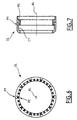
- Such a collector CL has a substantially annular shape as shown in Figures 6 and 7, to surround the cylinder CA, and to be possibly mounted on this cylinder by hooping. It comes under the shape of a ring which comprises on one of its faces normal to the axis longitudinal AL a plurality of longitudinal holes PC, which may be holes, and which are intended to receive stems of the TM sieve for hold this sieve on the CA suction cylinder.
- This collector includes a obviously in its inner part defining with the cylinder a cavity toric CT, visible in Figures 3 and 7.
- the CT toric cavity thus constituted communicates with the inside of the AC suction cylinder via slots FE of the cylinder provided for this purpose, and disposed opposite said toric cavity.
- this collector thus makes it possible to communicate a plurality of hollow rods with the inside of the suction cylinder via the CT cavity.
- this manifold also includes radial holes PT tapped radially relative to the longitudinal axis AL, and each communicating with a corresponding PC piercing.
- Each hole radial PT which can be obtained by drilling, opens on a surface external collector to be accessible from the outside. With those PT radial holes, it is possible to close the end of the rod corresponding by introducing a long screw that will reach the bottom of the corresponding hole PC or not to close this end by inserting a short screw to release the PC drilling corresponding.
- the pressure drop introduced by the drain element can be adjusted on site, choosing the number of collection rods communicating with the interior of the suction cylinder.
- the pressure drop induced by a collection rod TC can be further increased by connecting this rod of collecting inside the suction cylinder via a rod of TT transport or several TT transport rods connected in series.
- the induced loss of pressure is thus increased by lengthening the path that must travel the fluid from the OC collection port to reach the inside of the cylinder CA.
- the TT transport rods are hollow tubular sieve rods that can be made in the same material that the collection stems, but not necessarily presenting of collection port.
- the TM screen may comprise by example alternating TC collection rods and TT transport rods connected two by two.
- a collection rod will have one closed end, its other end connected to one end of a rod corresponding transport, and the transport rod will have its second end not closed to be connected inside the cylinder CA.
- this configuration is given as a non-limitative example and that other configurations are possible such as for example a alternation of a TC collection rod and two TT transport rods, in view to similarly associate a collection rod with two transport rods connected in series.
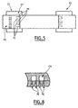
- transport rods and collection rods can be connected in series by a second collector CL.
- Such second collector CL will have a shape substantially similar to that illustrated in Figures 6 and 7, while including channels connecting holes Successive PCs, as shown in Figure 8, so that two successive holes will be interconnected by a CN channel instead of being connected to a toric cavity.
- a first collector as shown in Figures 6 and 7 at one end of the drain element, and a second collector as described in FIG. the other end of the drain element, we obtain the association of rods described in Figure 5.
- the drain element As can be seen, in the drain element according to the invention, it is the stems forming the sieve that collect and transport the hydrocarbon to inside the suction cylinder, and these rods can be associated according to a wide variety of combinations, in order to better adjust the loss of charge introduced by the drain element.
Landscapes
- Mining & Mineral Resources (AREA)
- Engineering & Computer Science (AREA)
- Geology (AREA)
- Life Sciences & Earth Sciences (AREA)
- Geochemistry & Mineralogy (AREA)
- General Life Sciences & Earth Sciences (AREA)
- Fluid Mechanics (AREA)
- Physics & Mathematics (AREA)
- Environmental & Geological Engineering (AREA)
- Chemical & Material Sciences (AREA)
- Dispersion Chemistry (AREA)
- Chemical Kinetics & Catalysis (AREA)
- Treatment Of Liquids With Adsorbents In General (AREA)
- Filtering Of Dispersed Particles In Gases (AREA)
- Lubrication Details And Ventilation Of Internal Combustion Engines (AREA)
- Separation Of Solids By Using Liquids Or Pneumatic Power (AREA)
- Treatment Of Water By Ion Exchange (AREA)
- Filtration Of Liquid (AREA)
Description
Claims (7)
- Crépine ayant un tamis de filtration constitué par un fil métallique (FI) enroulé autour et fixé à une structure tubulaire formée par des tiges qul s'étendent selon une direction longitudinale (AL) entre deux bagues, les tiges étant insérées par leurs deux extrémités dans les deux bagues en étant régulièrement réparties à la périphérie des bagues, l'une des bagues comportant une cavité intérieure (CT), caractérisée en ce que une ou plusieurs des tiges est ou sont des tiges creuses (TC) qui comportent chacune un orifice latéral (OC) et qui communiquent avec la cavité intérieure de la bague par une de leurs extrémités de telle sorte qu'un fluide peut pénétrer de l'extérieur de la crépine jusqu'à la cavité intérieure de la bague ou inversement.
- Elément de drain pour collecter notamment des hydrocarbures, comprenant une crépine selon la revendication 1 dans laquelle le tamis de filtration de la crépine entoure un cylindre d'aspiration (CA) sur lequel sont montées les deux bagues (CL) pour constituer un système pour régler la perte de charge introduite par l'élément de drain, le cylindre d'aspiration (CA) communiquant avec ladite cavité intérieure (CT) de la bague de telle sorte que l'hydrocarbure peut être amené avec un débit contrôlé de l'extérieur de la crépine vers l'intérieur du cylindre d'aspiration à travers les tiges creuses du tamis de filtration.
- Elément de drain selon la revendication 2, dans lequel des canaux. (CN) sont formés à l'intérieur des bagues (CL) pour raccorder-les unes aux autres les tiges creuses avec possibilité de modifier la perte de charge introduite par l'élément de drain à l'aide de vis montées dans les bagues depuis l'extérieur de celles-ci pour obturer les canaux (CN).
- Elément de drain selon la revendication 3, dans lequel les tiges incluent d'autres tiges creuses sans orifice latéral forment des tiges de transport (TT) et dans lequel les vis sont montées de telle manière à raccorder l'orifice latéral (OC) d'une tige creuse de collecte (TC) à ladite cavité intérieure (CT) de la bague par l'intermédiaire d'une ou plusieurs tiges creuses de transport (TT).
- Elément de drain selon l'une des revendications 1 à 4, dans lequel l'orifice latéral (OC) de chaque tige creuse est réalisé par perçage ou sciage partiel de la tige creuse.
- Elément de drain selon l'une des revendications 2 à 5, dans lequel la dite cavité intérieure (CT) de la bague communique avec l'intérieur du cylindre d'aspiration (CA) par des fentes (FE) formées dans le cylindre d'aspiration.
- Elément de drain selon l'une des revendications 2 à 6, dans lequel les bagues (CL) sont frettées sur le tube d'aspiration (CA).
Applications Claiming Priority (3)
| Application Number | Priority Date | Filing Date | Title |
|---|---|---|---|
| FR0012885 | 2000-10-09 | ||
| FR0012885A FR2815073B1 (fr) | 2000-10-09 | 2000-10-09 | Elements de drain ayant une crepine consitituee de tiges creuses pour collecter notamment des hydrocarbures |
| PCT/FR2001/002976 WO2002031314A1 (fr) | 2000-10-09 | 2001-09-26 | Element de drain ayant une crepine constituee de tiges creuses pour collecter notamment des hydrocarbures |
Publications (2)
| Publication Number | Publication Date |
|---|---|
| EP1327052A1 EP1327052A1 (fr) | 2003-07-16 |
| EP1327052B1 true EP1327052B1 (fr) | 2004-12-01 |
Family
ID=8855136
Family Applications (1)
| Application Number | Title | Priority Date | Filing Date |
|---|---|---|---|
| EP01972210A Expired - Lifetime EP1327052B1 (fr) | 2000-10-09 | 2001-09-26 | Element de drain ayant une crepine constituee de tiges creuses pour collecter notamment des hydrocarbures |
Country Status (10)
| Country | Link |
|---|---|
| US (1) | US6851560B2 (fr) |
| EP (1) | EP1327052B1 (fr) |
| AT (1) | ATE283965T1 (fr) |
| AU (2) | AU9199701A (fr) |
| BR (1) | BR0114250A (fr) |
| DE (1) | DE60107594T2 (fr) |
| FR (1) | FR2815073B1 (fr) |
| PL (1) | PL360149A1 (fr) |
| WO (1) | WO2002031314A1 (fr) |
| ZA (1) | ZA200302652B (fr) |
Families Citing this family (39)
| Publication number | Priority date | Publication date | Assignee | Title |
|---|---|---|---|---|
| NO314701B3 (no) * | 2001-03-20 | 2007-10-08 | Reslink As | Stromningsstyreanordning for struping av innstrommende fluider i en bronn |
| ATE315165T1 (de) * | 2001-12-13 | 2006-02-15 | Schlumberger Technology Bv | Verfahren und vorrichtung zum ausrüsten eines bohrloches |
| FR2845617B1 (fr) * | 2002-10-09 | 2006-04-28 | Inst Francais Du Petrole | Crepine a perte de charge controlee |
| NO319620B1 (no) * | 2003-02-17 | 2005-09-05 | Rune Freyer | Anordning og fremgangsmåte for valgbart å kunne stenge av et parti av en brønn |
| NO325434B1 (no) * | 2004-05-25 | 2008-05-05 | Easy Well Solutions As | Fremgangsmate og anordning for a ekspandere et legeme under overtrykk |
| US7673678B2 (en) * | 2004-12-21 | 2010-03-09 | Schlumberger Technology Corporation | Flow control device with a permeable membrane |
| US7543641B2 (en) * | 2006-03-29 | 2009-06-09 | Schlumberger Technology Corporation | System and method for controlling wellbore pressure during gravel packing operations |
| MX2008011191A (es) * | 2006-04-03 | 2008-09-09 | Exxonmobil Upstream Res Co | Metodo de sondeo y aparato para el control de afluencia y arena durante las operaciones de pozo. |
| US7708068B2 (en) * | 2006-04-20 | 2010-05-04 | Halliburton Energy Services, Inc. | Gravel packing screen with inflow control device and bypass |
| US8453746B2 (en) * | 2006-04-20 | 2013-06-04 | Halliburton Energy Services, Inc. | Well tools with actuators utilizing swellable materials |
| US7469743B2 (en) * | 2006-04-24 | 2008-12-30 | Halliburton Energy Services, Inc. | Inflow control devices for sand control screens |
| US7802621B2 (en) * | 2006-04-24 | 2010-09-28 | Halliburton Energy Services, Inc. | Inflow control devices for sand control screens |
| US7857050B2 (en) * | 2006-05-26 | 2010-12-28 | Schlumberger Technology Corporation | Flow control using a tortuous path |
| GB0615042D0 (en) * | 2006-07-29 | 2006-09-06 | Boyle Colin | Flow restrictor coupling |
| US20080041580A1 (en) * | 2006-08-21 | 2008-02-21 | Rune Freyer | Autonomous inflow restrictors for use in a subterranean well |
| US20080041588A1 (en) * | 2006-08-21 | 2008-02-21 | Richards William M | Inflow Control Device with Fluid Loss and Gas Production Controls |
| US20080041582A1 (en) * | 2006-08-21 | 2008-02-21 | Geirmund Saetre | Apparatus for controlling the inflow of production fluids from a subterranean well |
| US8025072B2 (en) * | 2006-12-21 | 2011-09-27 | Schlumberger Technology Corporation | Developing a flow control system for a well |
| AU2007346700B2 (en) | 2007-02-06 | 2013-10-31 | Halliburton Energy Services, Inc. | Swellable packer with enhanced sealing capability |
| US20080283238A1 (en) * | 2007-05-16 | 2008-11-20 | William Mark Richards | Apparatus for autonomously controlling the inflow of production fluids from a subterranean well |
| US7789145B2 (en) * | 2007-06-20 | 2010-09-07 | Schlumberger Technology Corporation | Inflow control device |
| US20090000787A1 (en) * | 2007-06-27 | 2009-01-01 | Schlumberger Technology Corporation | Inflow control device |
| US9004155B2 (en) * | 2007-09-06 | 2015-04-14 | Halliburton Energy Services, Inc. | Passive completion optimization with fluid loss control |
| US20090211965A1 (en) * | 2008-02-21 | 2009-08-27 | Weatherford/Lamb, Inc. | Arrangement for splicing panels together to form a cylindrical screen |
| US8028691B2 (en) * | 2008-10-27 | 2011-10-04 | Johnson Screens, Inc. | Passive solar wire screens for buildings |
| US9109423B2 (en) | 2009-08-18 | 2015-08-18 | Halliburton Energy Services, Inc. | Apparatus for autonomous downhole fluid selection with pathway dependent resistance system |
| US8376058B2 (en) | 2009-11-18 | 2013-02-19 | David K. Adamson | Well drilling wash down end cap and method |
| US8291976B2 (en) * | 2009-12-10 | 2012-10-23 | Halliburton Energy Services, Inc. | Fluid flow control device |
| US8708050B2 (en) | 2010-04-29 | 2014-04-29 | Halliburton Energy Services, Inc. | Method and apparatus for controlling fluid flow using movable flow diverter assembly |
| US9023456B2 (en) | 2011-03-18 | 2015-05-05 | Bilfinger Water Technologies, Inc. | Profiled wire screen for process flow and other applications |
| MY164163A (en) | 2011-04-08 | 2017-11-30 | Halliburton Energy Services Inc | Method and apparatus for controlling fluid flow in an autonomous valve using a sticky switch |
| CA2848963C (fr) | 2011-10-31 | 2015-06-02 | Halliburton Energy Services, Inc | Dispositif de regulation autonome du debit comprenant une plaque formant vanne pour la selection de fluide en fond de puits |
| SG2014010037A (en) | 2011-10-31 | 2014-05-29 | Halliburton Energy Services Inc | Autonomous fluid control device having a reciprocating valve for downhole fluid selection |
| US9404349B2 (en) | 2012-10-22 | 2016-08-02 | Halliburton Energy Services, Inc. | Autonomous fluid control system having a fluid diode |
| US9695654B2 (en) | 2012-12-03 | 2017-07-04 | Halliburton Energy Services, Inc. | Wellhead flowback control system and method |
| US9127526B2 (en) | 2012-12-03 | 2015-09-08 | Halliburton Energy Services, Inc. | Fast pressure protection system and method |
| RU2724731C1 (ru) * | 2020-02-04 | 2020-06-25 | Николай Борисович Болотин | Скважинный фильтр |
| RU2729670C1 (ru) * | 2020-02-04 | 2020-08-11 | Николай Борисович Болотин | Скважинный фильтр |
| RU2726657C1 (ru) * | 2020-02-05 | 2020-07-15 | Николай Борисович Болотин | Скважинный фильтр |
Family Cites Families (6)
| Publication number | Priority date | Publication date | Assignee | Title |
|---|---|---|---|---|
| US4088580A (en) * | 1976-12-01 | 1978-05-09 | Spurlock James W | Cluster screen for sand control |
| NO306127B1 (no) | 1992-09-18 | 1999-09-20 | Norsk Hydro As | Fremgangsmate og produksjonsror for produksjon av olje eller gass fra et olje- eller gassreservoar |
| US5803179A (en) * | 1996-12-31 | 1998-09-08 | Halliburton Energy Services, Inc. | Screened well drainage pipe structure with sealed, variable length labyrinth inlet flow control apparatus |
| US5868200A (en) * | 1997-04-17 | 1999-02-09 | Mobil Oil Corporation | Alternate-path well screen having protected shunt connection |
| CA2236944C (fr) * | 1997-05-06 | 2005-12-13 | Baker Hughes Incorporated | Dispositif et methodes de reglage de debit |
| AU3219000A (en) * | 1999-01-29 | 2000-08-18 | Schlumberger Technology Corporation | Controlling production |
-
2000
- 2000-10-09 FR FR0012885A patent/FR2815073B1/fr not_active Expired - Fee Related
-
2001
- 2001-09-26 PL PL36014901A patent/PL360149A1/xx not_active IP Right Cessation
- 2001-09-26 AU AU9199701A patent/AU9199701A/xx active Pending
- 2001-09-26 BR BR0114250-0A patent/BR0114250A/pt not_active IP Right Cessation
- 2001-09-26 ZA ZA200302652A patent/ZA200302652B/en unknown
- 2001-09-26 US US10/380,519 patent/US6851560B2/en not_active Expired - Lifetime
- 2001-09-26 WO PCT/FR2001/002976 patent/WO2002031314A1/fr not_active Ceased
- 2001-09-26 EP EP01972210A patent/EP1327052B1/fr not_active Expired - Lifetime
- 2001-09-26 DE DE60107594T patent/DE60107594T2/de not_active Expired - Lifetime
- 2001-09-26 AT AT01972210T patent/ATE283965T1/de not_active IP Right Cessation
- 2001-09-26 AU AU2001291997A patent/AU2001291997B2/en not_active Ceased
Also Published As
| Publication number | Publication date |
|---|---|
| ZA200302652B (en) | 2004-04-05 |
| US6851560B2 (en) | 2005-02-08 |
| FR2815073B1 (fr) | 2002-12-06 |
| DE60107594T2 (de) | 2005-04-28 |
| AU2001291997B2 (en) | 2005-06-30 |
| ATE283965T1 (de) | 2004-12-15 |
| AU9199701A (en) | 2002-04-22 |
| WO2002031314A1 (fr) | 2002-04-18 |
| EP1327052A1 (fr) | 2003-07-16 |
| FR2815073A1 (fr) | 2002-04-12 |
| US20040031607A1 (en) | 2004-02-19 |
| DE60107594D1 (de) | 2005-01-05 |
| PL360149A1 (en) | 2004-09-06 |
| BR0114250A (pt) | 2003-10-07 |
Similar Documents
| Publication | Publication Date | Title |
|---|---|---|
| EP1327052A1 (fr) | Element de drain ayant une crepine constituee de tiges creuses pour collecter notamment des hydrocarbures | |
| EP1407806B1 (fr) | Crépine à perte de charge controlée | |
| FR2762356A1 (fr) | Ecran de puits de forage a circuits de substitution | |
| EP0145552B1 (fr) | Filtre à deux empilements distincts de filtration | |
| FR2754306A1 (fr) | Element filtrant pour puits | |
| FR2477643A1 (fr) | Perfectionnement aux pompes electromagnetiques, en particulier pour fluides non visqueux | |
| FR2746659A1 (fr) | Valve pour le traitement de l'hydrocephalie | |
| FR2598629A1 (fr) | Module de filtration d'un liquide sous pression | |
| FR2845726A1 (fr) | Dispositif de reglage de debit au travers d'un tube de production place dans un puits petrolier | |
| EP0517329B1 (fr) | Tarière creuse pour la réalisation de pieux moulés dans le sol, et dispositif de forage comportant au moins deux de ces tarières | |
| EP1372811B1 (fr) | Element cylindrique a ailettes inclinees pour element filtrant et ensemble de filtrage correspondant | |
| FR2678987A1 (fr) | Pompe immergee notamment pour puits et forages composee de modules superposables. | |
| CA2044330C (fr) | Methode et dispositif perfectionnes pour ameliorer les diagraphies de production d'un puits non eruptif active | |
| FR2634253A1 (fr) | Dispositif de pompage a pistons multiples et piston pour ce dispositif | |
| WO2003064915A1 (fr) | Raccord pour sonde geothermique | |
| WO2017092903A1 (fr) | Palier hydrodynamique | |
| EP1979077B1 (fr) | Element de filtration | |
| EP1307273B1 (fr) | Boitier de microfiltration | |
| FR2476773A1 (fr) | Systeme de montage hydrostatique | |
| FR2898513A1 (fr) | Element de filtration. | |
| FR2684311A1 (fr) | Crepine, sonde ou drain dont le corps poreux est compose d'un agglomerat de particules de matieres plastique. | |
| FR2480814A1 (fr) | Tamis classeur pour l'industrie du papier | |
| FR2847177A1 (fr) | Tuyau d'epandage a debit reglable | |
| EP2088280B1 (fr) | Système pour positionner un corps dans un tube | |
| FR2552121A1 (fr) | Filtre pour pompes de vidange de machines a laver |
Legal Events
| Date | Code | Title | Description |
|---|---|---|---|
| PUAI | Public reference made under article 153(3) epc to a published international application that has entered the european phase |
Free format text: ORIGINAL CODE: 0009012 |
|
| 17P | Request for examination filed |
Effective date: 20030509 |
|
| AK | Designated contracting states |
Designated state(s): AT BE CH CY DE DK ES FI FR GB GR IE IT LI LU MC NL PT SE TR |
|
| AX | Request for extension of the european patent |
Extension state: AL LT LV MK RO SI |
|
| RIN1 | Information on inventor provided before grant (corrected) |
Inventor name: LAVERNHE, PHILIPPE, O. Inventor name: BRUXELLE, DAVID Inventor name: REIG, RAPHAEL |
|
| 17Q | First examination report despatched |
Effective date: 20040303 |
|
| GRAP | Despatch of communication of intention to grant a patent |
Free format text: ORIGINAL CODE: EPIDOSNIGR1 |
|
| GRAS | Grant fee paid |
Free format text: ORIGINAL CODE: EPIDOSNIGR3 |
|
| GRAA | (expected) grant |
Free format text: ORIGINAL CODE: 0009210 |
|
| AK | Designated contracting states |
Kind code of ref document: B1 Designated state(s): AT BE CH CY DE DK ES FI FR GB GR IE IT LI LU MC NL PT SE TR |
|
| PG25 | Lapsed in a contracting state [announced via postgrant information from national office to epo] |
Ref country code: TR Free format text: LAPSE BECAUSE OF FAILURE TO SUBMIT A TRANSLATION OF THE DESCRIPTION OR TO PAY THE FEE WITHIN THE PRESCRIBED TIME-LIMIT Effective date: 20041201 Ref country code: NL Free format text: LAPSE BECAUSE OF FAILURE TO SUBMIT A TRANSLATION OF THE DESCRIPTION OR TO PAY THE FEE WITHIN THE PRESCRIBED TIME-LIMIT Effective date: 20041201 Ref country code: IT Free format text: LAPSE BECAUSE OF FAILURE TO SUBMIT A TRANSLATION OF THE DESCRIPTION OR TO PAY THE FEE WITHIN THE PRESCRIBED TIME-LIMIT;WARNING: LAPSES OF ITALIAN PATENTS WITH EFFECTIVE DATE BEFORE 2007 MAY HAVE OCCURRED AT ANY TIME BEFORE 2007. THE CORRECT EFFECTIVE DATE MAY BE DIFFERENT FROM THE ONE RECORDED. Effective date: 20041201 Ref country code: GB Free format text: LAPSE BECAUSE OF FAILURE TO SUBMIT A TRANSLATION OF THE DESCRIPTION OR TO PAY THE FEE WITHIN THE PRESCRIBED TIME-LIMIT Effective date: 20041201 Ref country code: FI Free format text: LAPSE BECAUSE OF FAILURE TO SUBMIT A TRANSLATION OF THE DESCRIPTION OR TO PAY THE FEE WITHIN THE PRESCRIBED TIME-LIMIT Effective date: 20041201 Ref country code: AT Free format text: LAPSE BECAUSE OF FAILURE TO SUBMIT A TRANSLATION OF THE DESCRIPTION OR TO PAY THE FEE WITHIN THE PRESCRIBED TIME-LIMIT Effective date: 20041201 |
|
| REG | Reference to a national code |
Ref country code: GB Ref legal event code: FG4D Free format text: NOT ENGLISH |
|
| REG | Reference to a national code |
Ref country code: CH Ref legal event code: EP |
|
| REG | Reference to a national code |
Ref country code: IE Ref legal event code: FG4D Free format text: FRENCH |
|
| REF | Corresponds to: |
Ref document number: 60107594 Country of ref document: DE Date of ref document: 20050105 Kind code of ref document: P |
|
| PG25 | Lapsed in a contracting state [announced via postgrant information from national office to epo] |
Ref country code: GR Free format text: LAPSE BECAUSE OF FAILURE TO SUBMIT A TRANSLATION OF THE DESCRIPTION OR TO PAY THE FEE WITHIN THE PRESCRIBED TIME-LIMIT Effective date: 20050301 Ref country code: DK Free format text: LAPSE BECAUSE OF FAILURE TO SUBMIT A TRANSLATION OF THE DESCRIPTION OR TO PAY THE FEE WITHIN THE PRESCRIBED TIME-LIMIT Effective date: 20050301 |
|
| REG | Reference to a national code |
Ref country code: SE Ref legal event code: TRGR |
|
| PG25 | Lapsed in a contracting state [announced via postgrant information from national office to epo] |
Ref country code: ES Free format text: LAPSE BECAUSE OF FAILURE TO SUBMIT A TRANSLATION OF THE DESCRIPTION OR TO PAY THE FEE WITHIN THE PRESCRIBED TIME-LIMIT Effective date: 20050312 |
|
| NLV1 | Nl: lapsed or annulled due to failure to fulfill the requirements of art. 29p and 29m of the patents act | ||
| GBV | Gb: ep patent (uk) treated as always having been void in accordance with gb section 77(7)/1977 [no translation filed] |
Effective date: 20041201 |
|
| PGFP | Annual fee paid to national office [announced via postgrant information from national office to epo] |
Ref country code: SE Payment date: 20050914 Year of fee payment: 5 |
|
| PGFP | Annual fee paid to national office [announced via postgrant information from national office to epo] |
Ref country code: IE Payment date: 20050920 Year of fee payment: 5 |
|
| PG25 | Lapsed in a contracting state [announced via postgrant information from national office to epo] |
Ref country code: CY Free format text: LAPSE BECAUSE OF FAILURE TO SUBMIT A TRANSLATION OF THE DESCRIPTION OR TO PAY THE FEE WITHIN THE PRESCRIBED TIME-LIMIT Effective date: 20050926 |
|
| PG25 | Lapsed in a contracting state [announced via postgrant information from national office to epo] |
Ref country code: MC Free format text: LAPSE BECAUSE OF NON-PAYMENT OF DUE FEES Effective date: 20050930 Ref country code: LU Free format text: LAPSE BECAUSE OF NON-PAYMENT OF DUE FEES Effective date: 20050930 Ref country code: LI Free format text: LAPSE BECAUSE OF NON-PAYMENT OF DUE FEES Effective date: 20050930 Ref country code: CH Free format text: LAPSE BECAUSE OF NON-PAYMENT OF DUE FEES Effective date: 20050930 |
|
| PLBE | No opposition filed within time limit |
Free format text: ORIGINAL CODE: 0009261 |
|
| STAA | Information on the status of an ep patent application or granted ep patent |
Free format text: STATUS: NO OPPOSITION FILED WITHIN TIME LIMIT |
|
| 26N | No opposition filed |
Effective date: 20050902 |
|
| REG | Reference to a national code |
Ref country code: CH Ref legal event code: PL |
|
| PG25 | Lapsed in a contracting state [announced via postgrant information from national office to epo] |
Ref country code: IE Free format text: LAPSE BECAUSE OF NON-PAYMENT OF DUE FEES Effective date: 20060926 |
|
| PG25 | Lapsed in a contracting state [announced via postgrant information from national office to epo] |
Ref country code: SE Free format text: LAPSE BECAUSE OF NON-PAYMENT OF DUE FEES Effective date: 20060927 |
|
| EUG | Se: european patent has lapsed | ||
| REG | Reference to a national code |
Ref country code: IE Ref legal event code: MM4A |
|
| PG25 | Lapsed in a contracting state [announced via postgrant information from national office to epo] |
Ref country code: PT Free format text: LAPSE BECAUSE OF NON-PAYMENT OF DUE FEES Effective date: 20050501 |
|
| REG | Reference to a national code |
Ref country code: FR Ref legal event code: CD Owner name: BILFINGER WATER TECHNOLOGIES Effective date: 20131223 |
|
| REG | Reference to a national code |
Ref country code: DE Ref legal event code: R082 Ref document number: 60107594 Country of ref document: DE Representative=s name: MOSER GOETZE & PARTNER PATENTANWAELTE MBB, DE Effective date: 20140618 Ref country code: DE Ref legal event code: R082 Ref document number: 60107594 Country of ref document: DE Representative=s name: MOSER & GOETZE PATENTANWAELTE, DE Effective date: 20140618 Ref country code: DE Ref legal event code: R081 Ref document number: 60107594 Country of ref document: DE Owner name: BILFINGER WATER TECHNOLOGIES, FR Free format text: FORMER OWNER: JOHNSON FILTRATION SYSTEMS, AVAILLES EN CHATELLERAULT, FR Effective date: 20140618 |
|
| REG | Reference to a national code |
Ref country code: FR Ref legal event code: PLFP Year of fee payment: 16 |
|
| REG | Reference to a national code |
Ref country code: FR Ref legal event code: PLFP Year of fee payment: 17 |
|
| REG | Reference to a national code |
Ref country code: FR Ref legal event code: PLFP Year of fee payment: 18 |
|
| PGFP | Annual fee paid to national office [announced via postgrant information from national office to epo] |
Ref country code: FR Payment date: 20200812 Year of fee payment: 20 Ref country code: DE Payment date: 20200916 Year of fee payment: 20 |
|
| PGFP | Annual fee paid to national office [announced via postgrant information from national office to epo] |
Ref country code: BE Payment date: 20200817 Year of fee payment: 20 |
|
| REG | Reference to a national code |
Ref country code: DE Ref legal event code: R071 Ref document number: 60107594 Country of ref document: DE |
|
| REG | Reference to a national code |
Ref country code: BE Ref legal event code: MK Effective date: 20210926 |