EP1326758B1 - Folding convertible top with integral boot - Google Patents
Folding convertible top with integral boot Download PDFInfo
- Publication number
- EP1326758B1 EP1326758B1 EP01988343A EP01988343A EP1326758B1 EP 1326758 B1 EP1326758 B1 EP 1326758B1 EP 01988343 A EP01988343 A EP 01988343A EP 01988343 A EP01988343 A EP 01988343A EP 1326758 B1 EP1326758 B1 EP 1326758B1
- Authority
- EP
- European Patent Office
- Prior art keywords
- rail
- header
- convertible top
- linkage
- folding
- Prior art date
- Legal status (The legal status is an assumption and is not a legal conclusion. Google has not performed a legal analysis and makes no representation as to the accuracy of the status listed.)
- Expired - Lifetime
Links
- 230000000063 preceeding effect Effects 0.000 claims 2
- 239000000463 material Substances 0.000 description 2
- 230000004308 accommodation Effects 0.000 description 1
- 238000009825 accumulation Methods 0.000 description 1
- 239000000356 contaminant Substances 0.000 description 1
- 239000000428 dust Substances 0.000 description 1
- 239000004744 fabric Substances 0.000 description 1
- 238000009434 installation Methods 0.000 description 1
- 230000004048 modification Effects 0.000 description 1
- 238000012986 modification Methods 0.000 description 1
Images




Classifications
-
- B—PERFORMING OPERATIONS; TRANSPORTING
- B60—VEHICLES IN GENERAL
- B60J—WINDOWS, WINDSCREENS, NON-FIXED ROOFS, DOORS, OR SIMILAR DEVICES FOR VEHICLES; REMOVABLE EXTERNAL PROTECTIVE COVERINGS SPECIALLY ADAPTED FOR VEHICLES
- B60J7/00—Non-fixed roofs; Roofs with movable panels, e.g. rotary sunroofs
- B60J7/08—Non-fixed roofs; Roofs with movable panels, e.g. rotary sunroofs of non-sliding type, i.e. movable or removable roofs or panels, e.g. let-down tops or roofs capable of being easily detached or of assuming a collapsed or inoperative position
- B60J7/12—Non-fixed roofs; Roofs with movable panels, e.g. rotary sunroofs of non-sliding type, i.e. movable or removable roofs or panels, e.g. let-down tops or roofs capable of being easily detached or of assuming a collapsed or inoperative position foldable; Tensioning mechanisms therefor, e.g. struts
- B60J7/1226—Soft tops for convertible vehicles
- B60J7/1265—Soft tops for convertible vehicles characterised by kinematic movements, e.g. using parallelogram linkages
Definitions
- This invention relates to vehicle convertible tops and, more particularly, to a top having a linkage which folds a top so that the header serves as a boot to cover the top when stored.
- tops Many different types of folding convertible soft and hard tops have been developed to enhance motoring pleasure by enabling a driver to selectively open and close the passenger compartment. These tops utilize a variety of different folding linkages, each of which are designed to accommodate the particular mechanical constraints of a specific vehicle application. It is desirable to utilize a top folding linkage that is simple, compact and stores the top in as little space as possible.
- the header When these tops are lowered into a storage compartment, the header is normally inverted. This requires that the top or a portion of the top to be covered by a soft or hard boot to prevent accumulation of dust or other contaminants that would be dumped into the passenger compartment when the header rotates as the top is raised.
- the boot may be manually installed, or, is automatically manipulated by power operators, usually hydraulic cylinders. Installation of these boots requires time and/or effort to install. In the case of the soft boot, it requires separate storage when removed to enable the top to be raised.
- US-5,810,422 regarded as most relevant prior art document, discloses a convertible top consisting of a rigid front panel, a rigid middle panel and a rear rail which are covered by a flexible covering. In the stored position, the middle panel is inverted and lies underneath the rear rail, which in turn is covered by the front panel. Thereby, the need for a separate cover is eliminated, since the front panel functions as a cover for the stored convertible top.
- US-5,207,474 shows a convertible top having a rigid front plate and a rear rail covered by a flexible covering. During the folding of the top, the rear rail is inverted and the rigid roof part is laid upon it so that it covers the folded flexible material of the top in folded position.
- this invention features a convertible top and a pair of side linkages for raising the top between a raised position, covering the vehicle body passenger compartment, through a body opening, and a lowered position folded into a storage compartment within the vehicle body.
- the top includes a cover, a header for engaging the vehicle windshield in top raised position, and at least one crossbow extending between the side linkages to support the cover in top raised position.
- Each side linkage includes a side rail pivoted to and extending rearwardly from the header and other links for folding the top in a Z-shaped folding action to a compact shape in the storage compartment such that the header is not inverted and covers the folded top and closes the body opening.
- This invention also features 4-bar side linkages that enable the top to fold in the Z-shape.
- Another feature of this invention is the use of a lost-motion connection between the header and a side rail to enable relative lateral movement during raising and lowering of the top.
- a convertible top 10 has a conventional flexible fabric, or other similar material, cover (not illustrated) that is supported at its front by a plate-like extended header, or 1-bow, 12, and an intermediate bow 14.
- the cover for top 10 is conventionally attached to the vehicle body (not illustrated).
- Header 12 extends sufficiently rearward so as to incorporate what would normally be an intermediate 2-bow.
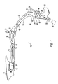
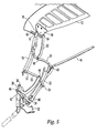
- These supporting bows are pivotally connected at each side by an articulated linkage, which is conventionally operable by hydraulic cylinders, or other means (not shown) to raise and lower the top between an extended raised position covering the vehicle passenger compartment (not illustrated), as shown in Fig. 1, through the intermediate positions shown in Figs. 2, 3 and 5, and a lowered and folded position, as shown in Fig. 4, within a storage compartment in a vehicle body (not illustrated).
- articulated linkage which is conventionally operable by hydraulic cylinders, or other means (not shown) to raise and lower the top between an extended raised position covering the vehicle passenger compartment (not illustrated), as shown in Fig. 1, through the intermediate positions shown in Figs. 2, 3 and 5, and a lowered and folded position, as shown in Fig. 4, within a storage compartment in a vehicle body (not illustrated).
- the linkages comprise a front rail 16 that is secured to, and moves with header 12.
- a middle rail 18 has a forward extension 20 that is connected to front rail 16, as will be later described.
- a rear rail 22 is pivoted adjacent its lower end at 24 to the rod 26 of a hydraulic cylinder 28, which is pivoted at 30 to a body-mounted mounting bracket 32.
- a lower control arm 34 is pivoted to bracket 32 at 36 and has an arm 38 that pivotally mounts one end 40 of a lower connecting link 42 that is pivoted at its other end 44 to the lower end 46 of rear rail 22.
- the upper end of lower control arm 34 is pivoted at 48 intermediate the ends of a middle connecting link 50 that has one end pivoted at 52 to middle rail 18 and its other end pivoted at 54 to an intermediate portion of rear rail 22.
- an upper connecting link 56 is pivoted at 58 to an intermediate portion of middle side rail 18, while its other end is pivoted to the upper end of rear rail 22 at 60.
- An upper control arm 62 is pivoted at 64 to a header-mounted bracket 66, and to an intermediate portion of upper connecting link 56 at 68.
- the linkage just described is duplicated on the other side of the vehicle. It comprises three four-bar linkages that allow the top 10 to fold into a very compact, layered arrangement. As can be seen from viewing the folding sequence illustrated in Figs. 1, 2, 3 and 4, top 10 folds into the form of a collapsed "Z". This is enabled by employing the four-bar linkages.
- the first linkage is formed by header 12, extension 20 of middle rail 18, upper control arm 62 and the upper portion of upper connecting link 56, as defined by pivots 64, 68, 58 and the connection 70 between extension 20 of middle rail 18 and front rail 16.
- the second four-bar linkage comprises upper connecting link 56, the lower portion of middle rail 18, middle connecting link 50 and the upper portion of rear rail 22, as defined by pivots 58, 52, 54 and 60.
- the third four-bar linkage is formed by the lower portion of middle connecting link 50, lower control arm 34, lower connecting link 42 and the lower portion of rear rail 22, as defined by pivots 48, 40, 44 and 54.
- the entire top 10 moves about body linkage pivot 36 and cylinder pivot 30, as controlled by cylinder 28 and the three four-bar linkages described above.
- This Z-fold provides a more compact arrangement requiring less space within the vehicle body than prior arrangements, while also enabling the extended header to cover the folded top and eliminate the necessity of using a separate boot cover.
Landscapes
- Engineering & Computer Science (AREA)
- Mechanical Engineering (AREA)
- Seats For Vehicles (AREA)
- Body Structure For Vehicles (AREA)
- Vehicle Step Arrangements And Article Storage (AREA)
- Seal Device For Vehicle (AREA)
Description
Claims (8)
- Convertible top (10) to be moved through a body opening between a raised position, covering the vehicle body passenger compartment, and a lowered position folded into a storage compartment within the vehicle body, said top including a header (12) for engaging the vehicle windshield in top raised position and a pair of side linkages and at least one crossbow (14) extending between the side linkages, each linkage comprising a front rail (16), a middle rail (18), a rear rail (22), and a plurality of links (34, 50, 56, 62) connecting the header (12), the front rail (16), the middle rail (18), the rear rail (20) and the crossbows (14) for folding the top (10) in a Z-shaped folding action to a compact shape in the storage compartment such that the header (12) is not inverted and covers the folded top (10) and closes the body opening,
characterised in that
the middle and rear rails (18, 22) are inverted during the folding action. - The convertible top of claim 1, wherein each side linkage includes a 4-bar linkage to accomplish the Z-shaped fold.
- The convertible top of claim 1, wherein each side linkage includes two 4-bar linkages to enable the Z-folding action.
- The convertible top of claim 1, wherein each side linkage includes three 4-bar linkages.
- The convertible top according to one of the preceeding claims, including a lost motion connection between a side rail and the header (12) to enable relative lateral movement during folding and unfolding of the top (10).
- The convertible top according to one of the preceeding claims, wherein the front rail (16) is mounted on the header (12), the middle rail (18) is pivoted to the header (12), the rear rail (22) is pivotally connected to the vehicle and spaced upper and middle connecting links (56, 50) interconnecting the middle and rear rails (18, 22) to form a 4-bar linkage.
- The convertible top according to one of claims 3 to 6, wherein each side linkage includes an upper control arm (62) interconnecting the upper connecting link (56) and the header (12) to form a second 4-bar linkage.
- The convertible top according to one of claims 4 to 7, wherein each side linkage includes a lower control arm (34) connecting the middle connecting link (50) and the vehicle body and a lower connecting link (42) connecting the rear rail (22) and the lower control arm (34) to form a third 4-bar linkage.
Applications Claiming Priority (3)
| Application Number | Priority Date | Filing Date | Title |
|---|---|---|---|
| US24228100P | 2000-10-20 | 2000-10-20 | |
| US242281P | 2000-10-20 | ||
| PCT/US2001/049236 WO2002043978A2 (en) | 2000-10-20 | 2001-10-20 | Folding convertible top with integral boot |
Publications (3)
| Publication Number | Publication Date |
|---|---|
| EP1326758A2 EP1326758A2 (en) | 2003-07-16 |
| EP1326758A4 EP1326758A4 (en) | 2004-03-17 |
| EP1326758B1 true EP1326758B1 (en) | 2005-06-08 |
Family
ID=22914164
Family Applications (1)
| Application Number | Title | Priority Date | Filing Date |
|---|---|---|---|
| EP01988343A Expired - Lifetime EP1326758B1 (en) | 2000-10-20 | 2001-10-20 | Folding convertible top with integral boot |
Country Status (5)
| Country | Link |
|---|---|
| EP (1) | EP1326758B1 (en) |
| JP (1) | JP4143688B2 (en) |
| AU (1) | AU2002241660A1 (en) |
| DE (1) | DE60111404T2 (en) |
| WO (1) | WO2002043978A2 (en) |
Cited By (1)
| Publication number | Priority date | Publication date | Assignee | Title |
|---|---|---|---|---|
| EP2406094B2 (en) † | 2009-03-12 | 2018-02-14 | Valmet Automotive Oy | Z-fold convertible top with two piece side rail |
Families Citing this family (8)
| Publication number | Priority date | Publication date | Assignee | Title |
|---|---|---|---|---|
| DE10160240B4 (en) * | 2001-12-07 | 2005-04-07 | Webasto Ag | Folding hood for a motor vehicle |
| DE10357098B3 (en) * | 2003-12-06 | 2005-05-25 | Wilhelm Karmann Gmbh | Cabriolet vehicle comprises a drive element arranged on a holder mounted in the vehicle body that also acts as a support for a control unit, a hydraulic pump and connectors of control lines leading to the drive units for roof movement |
| DE102004003022A1 (en) * | 2004-01-20 | 2005-08-11 | Wilhelm Karmann Gmbh | Convertible car |
| US7690716B2 (en) * | 2006-05-23 | 2010-04-06 | Specialty Vehicle Acquisition Corp. | Convertible roof |
| DE102006042202B4 (en) | 2006-09-08 | 2024-08-08 | Dr. Ing. H.C. F. Porsche Aktiengesellschaft | Convertible top drive |
| DE102008016812B4 (en) | 2008-04-02 | 2018-05-24 | Volkswagen Ag | Foldable top |
| FR2934206A1 (en) * | 2008-07-24 | 2010-01-29 | Peugeot Citroen Automobiles Sa | Flexible roof for e.g. electric vehicle, has main part with photovoltaic cells transforming solar energy into electric energy to power part of electrical equipments of vehicle, where part is flexible and foldable during opening of roof |
| DE102009051122A1 (en) * | 2009-10-28 | 2011-05-05 | Audi Ag | Cabriolet vehicle with a hood with Z folding principle |
Citations (2)
| Publication number | Priority date | Publication date | Assignee | Title |
|---|---|---|---|---|
| US2704225A (en) * | 1951-07-05 | 1955-03-15 | Kaiser Motors Corp | Convertible automobile top |
| EP0936095A2 (en) * | 1998-02-11 | 1999-08-18 | DaimlerChrysler AG | Hardtop vehicle |
Family Cites Families (8)
| Publication number | Priority date | Publication date | Assignee | Title |
|---|---|---|---|---|
| US3473842A (en) * | 1967-06-27 | 1969-10-21 | Ford Motor Co | Convertible top mechanism |
| DE3416286A1 (en) * | 1983-07-04 | 1984-10-04 | Dieter 4400 Münster Hötker | Upper roof component of a folding cover for motor vehicles |
| EP0521307B2 (en) * | 1991-07-04 | 2002-03-06 | Wilhelm Karmann GmbH | Folding hood for motorvehicle provided with a collapsible roof |
| US5429409A (en) * | 1993-01-04 | 1995-07-04 | Asc Incorporated | Convertible top |
| FI102468B1 (en) * | 1997-06-16 | 1998-12-15 | Valmet Automotive Oy | Open car with a hard roof construction that can be opened |
| US6478362B2 (en) * | 1999-12-22 | 2002-11-12 | Ed. Scharwaechter Gmbh | Convertible top and driving device for a convertible top |
| DE10008492A1 (en) * | 2000-02-24 | 2001-08-30 | Bayerische Motoren Werke Ag | Folding hood for a motor vehicle |
| DE10042460B4 (en) * | 2000-08-29 | 2010-06-17 | Webasto Ag | Retractable roof of a convertible vehicle |
-
2001
- 2001-10-20 JP JP2002545934A patent/JP4143688B2/en not_active Expired - Fee Related
- 2001-10-20 WO PCT/US2001/049236 patent/WO2002043978A2/en not_active Ceased
- 2001-10-20 AU AU2002241660A patent/AU2002241660A1/en not_active Abandoned
- 2001-10-20 DE DE60111404T patent/DE60111404T2/en not_active Expired - Fee Related
- 2001-10-20 EP EP01988343A patent/EP1326758B1/en not_active Expired - Lifetime
Patent Citations (2)
| Publication number | Priority date | Publication date | Assignee | Title |
|---|---|---|---|---|
| US2704225A (en) * | 1951-07-05 | 1955-03-15 | Kaiser Motors Corp | Convertible automobile top |
| EP0936095A2 (en) * | 1998-02-11 | 1999-08-18 | DaimlerChrysler AG | Hardtop vehicle |
Cited By (1)
| Publication number | Priority date | Publication date | Assignee | Title |
|---|---|---|---|---|
| EP2406094B2 (en) † | 2009-03-12 | 2018-02-14 | Valmet Automotive Oy | Z-fold convertible top with two piece side rail |
Also Published As
| Publication number | Publication date |
|---|---|
| DE60111404T2 (en) | 2005-10-27 |
| EP1326758A2 (en) | 2003-07-16 |
| WO2002043978A3 (en) | 2002-10-31 |
| EP1326758A4 (en) | 2004-03-17 |
| JP2004514590A (en) | 2004-05-20 |
| JP4143688B2 (en) | 2008-09-03 |
| WO2002043978A2 (en) | 2002-06-06 |
| DE60111404D1 (en) | 2005-07-14 |
| AU2002241660A1 (en) | 2002-06-11 |
Similar Documents
| Publication | Publication Date | Title |
|---|---|---|
| US7163255B2 (en) | Folding convertible top with integral boot | |
| US6422637B1 (en) | Retractable motor vehicle top as well as motor vehicle comprising this top | |
| US6572175B2 (en) | Lowerable roof of a convertible | |
| US5593202A (en) | Convertible top | |
| US20010005086A1 (en) | Retractable top trunk lid assembly | |
| US6729672B2 (en) | Retractable top quarter window assembly | |
| US6464284B2 (en) | Compact top stack linkage | |
| US7559596B2 (en) | Soft-top convertible roof | |
| US6062625A (en) | Variable roof box for a convertible | |
| US20050127708A1 (en) | Retracting mechanism for use with both hard and hybrid retractable tops for vehicles | |
| GB2333745A (en) | Rear lid mounting mechanism for a convertible motor vehicle | |
| US6796597B2 (en) | Retractable hard top with inboard connections | |
| US7032951B2 (en) | Convertible vehicle top stack mechanism | |
| US6796595B2 (en) | Vehicle convertible roof | |
| US7063371B2 (en) | Convertible hardtop roof | |
| US6755457B2 (en) | Vehicle convertible roof | |
| US6692061B1 (en) | Vehicle convertible roof | |
| US6722724B1 (en) | Four section retractable hard top | |
| EP1326758A2 (en) | Folding convertible top with integral boot | |
| US6921125B2 (en) | Foldable vehicle roof for a convertible vehicle | |
| EP1136295A2 (en) | Tonneau cover for covering the boot of a convertible, and a convertible | |
| US7735899B2 (en) | Convertible automobile | |
| EP2349758B1 (en) | Convertible top having overcenter backlight | |
| EP1555152B1 (en) | Mechanism for use with both hard and hybrid retractable cabrilolet vehicle tops | |
| US7344179B2 (en) | Retractable hardtop for a vehicle |
Legal Events
| Date | Code | Title | Description |
|---|---|---|---|
| PUAI | Public reference made under article 153(3) epc to a published international application that has entered the european phase |
Free format text: ORIGINAL CODE: 0009012 |
|
| 17P | Request for examination filed |
Effective date: 20030411 |
|
| AK | Designated contracting states |
Designated state(s): AT BE CH CY DE DK ES FI FR GB GR IE IT LI LU MC NL PT SE TR |
|
| AX | Request for extension of the european patent |
Extension state: AL LT LV MK RO SI |
|
| RIC1 | Information provided on ipc code assigned before grant |
Ipc: 7B 60J 7/14 B Ipc: 7B 60J 7/12 B Ipc: 7B 60J 7/20 A |
|
| A4 | Supplementary search report drawn up and despatched |
Effective date: 20040130 |
|
| 17Q | First examination report despatched |
Effective date: 20040210 |
|
| RBV | Designated contracting states (corrected) |
Designated state(s): DE GB |
|
| GRAP | Despatch of communication of intention to grant a patent |
Free format text: ORIGINAL CODE: EPIDOSNIGR1 |
|
| GRAS | Grant fee paid |
Free format text: ORIGINAL CODE: EPIDOSNIGR3 |
|
| GRAA | (expected) grant |
Free format text: ORIGINAL CODE: 0009210 |
|
| AK | Designated contracting states |
Kind code of ref document: B1 Designated state(s): DE GB |
|
| REG | Reference to a national code |
Ref country code: GB Ref legal event code: FG4D |
|
| REF | Corresponds to: |
Ref document number: 60111404 Country of ref document: DE Date of ref document: 20050714 Kind code of ref document: P |
|
| PG25 | Lapsed in a contracting state [announced via postgrant information from national office to epo] |
Ref country code: GB Free format text: LAPSE BECAUSE OF NON-PAYMENT OF DUE FEES Effective date: 20051020 |
|
| PLBE | No opposition filed within time limit |
Free format text: ORIGINAL CODE: 0009261 |
|
| STAA | Information on the status of an ep patent application or granted ep patent |
Free format text: STATUS: NO OPPOSITION FILED WITHIN TIME LIMIT |
|
| PG25 | Lapsed in a contracting state [announced via postgrant information from national office to epo] |
Ref country code: DE Free format text: LAPSE BECAUSE OF NON-PAYMENT OF DUE FEES Effective date: 20060503 |
|
| 26N | No opposition filed |
Effective date: 20060309 |
|
| GBPC | Gb: european patent ceased through non-payment of renewal fee |
Effective date: 20051020 |