EP1326466B1 - Method of communication in a network - Google Patents
Method of communication in a network Download PDFInfo
- Publication number
- EP1326466B1 EP1326466B1 EP02293254A EP02293254A EP1326466B1 EP 1326466 B1 EP1326466 B1 EP 1326466B1 EP 02293254 A EP02293254 A EP 02293254A EP 02293254 A EP02293254 A EP 02293254A EP 1326466 B1 EP1326466 B1 EP 1326466B1
- Authority
- EP
- European Patent Office
- Prior art keywords
- mobile terminal
- access point
- network
- beacon signal
- given
- Prior art date
- Legal status (The legal status is an assumption and is not a legal conclusion. Google has not performed a legal analysis and makes no representation as to the accuracy of the status listed.)
- Expired - Lifetime
Links
- 238000000034 method Methods 0.000 title claims description 18
- 238000004891 communication Methods 0.000 title claims description 9
- 230000005540 biological transmission Effects 0.000 claims description 11
- 238000004364 calculation method Methods 0.000 claims description 6
- 238000012360 testing method Methods 0.000 description 17
- 238000007726 management method Methods 0.000 description 14
- 238000010586 diagram Methods 0.000 description 7
- 238000012790 confirmation Methods 0.000 description 6
- 230000004044 response Effects 0.000 description 6
- 230000011664 signaling Effects 0.000 description 4
- 238000012545 processing Methods 0.000 description 3
- 230000001419 dependent effect Effects 0.000 description 2
- 230000006870 function Effects 0.000 description 2
- 238000013475 authorization Methods 0.000 description 1
- 238000013523 data management Methods 0.000 description 1
- 230000008054 signal transmission Effects 0.000 description 1
- 238000012795 verification Methods 0.000 description 1
Images




Classifications
-
- H—ELECTRICITY
- H04—ELECTRIC COMMUNICATION TECHNIQUE
- H04W—WIRELESS COMMUNICATION NETWORKS
- H04W48/00—Access restriction; Network selection; Access point selection
- H04W48/08—Access restriction or access information delivery, e.g. discovery data delivery
- H04W48/12—Access restriction or access information delivery, e.g. discovery data delivery using downlink control channel
Definitions
- the present invention relates to a method of communication in a network.
- the invention is in the field of wireless networks. These networks may be highly centralized, have one base station which manages the whole network and allocates network access to the various members, or else may be more distributed, that is to say that the decisions about network access are the result of one or more terminals deciding the rights of network access for themselves or for the others.
- beacon channel for network management information
- payload data data carried by the base station
- the terminal is capable of transmitting a certain amount of information to the base station, in order to describe its own situation in relation to the network.
- Document EP-A-0 490 441 discloses a method of operating a communications system in which secondary stations are able to roam in and out of respective radio coverage areas of a plurality of fixedly sited primary stations, such stations regularly transmitting idle beacon signals which are detectable by in range secondary stations operating in an idle locked state.
- Document WO-A-95 31080 discloses a method for establishing a communication link between a communication device and authorization equipment.
- beacon channel The commencement of the existence of a wireless network, on switching on the elements which make it up, is generally characterized by the presence of a beacon channel.
- this beacon channel is attributed to a base station which is an access point to a wired network.
- a base station or an access point begins to transmit over a beacon channel as soon as it is turned on, or a mobile terminal that is turned on detects the lack of a beacon channel and declares itself to be a base station, whether or not it is an access point.
- the network under consideration is a mixed network, that is to say having a wired part and a wireless part, where the access points are multiple and linked to the same wired network.
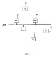
- a mixed network is shown in Figure 1 .
- the references MT0 and MT1 in the Figure represent mobile terminals and AP0, AP1, and AP2 represent access points linked to the same wired network.
- the object of the present invention is to remedy the disadvantages described above.
- the present invention provides an access point in accordance with claim 1 and a mobile terminal in accordance with claim 4.
- Other features are recited in the dependent claims.
- a temporary wireless network is created between the pre-existing mobile terminals and access points. If there is no need for this network, no transmission takes place on the beacon channel. In other words, the network is only put into operation in the presence of a person operating his or her mobile terminal.
- the temporary network is only maintained if necessary.
- An advantage of the present invention is that it makes it possible to save energy.
- the present invention makes it possible to avoid congesting the radio frequency space when there is no network user, since the temporary network is cut off in that case.
- the object of the present invention is to create a beacon channel and thereby a wireless network, at the initiative of the mobile terminal, then to re-attribute this beacon channel to a point of access to the wired network, at the same time as the management of the access to the wireless network.
- all the terminals are capable of transmitting and receiving information over at least one beacon channel, in addition to their minimum capability of receiving or transmitting over a signaling channel, and vice-versa.
- the mobile items of equipment must be capable of measuring a period of time.
- the mobile terminals possess an authentication system as well as an authentication key.
- This authentication key is held in a memory.
- This memory may be pre-loaded by the manufacturer or by a suitable system, as for example in a procedure for terminal - base station association by means of a cable, the manufacturer having pre-loaded the key in one of the two elements.
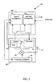
- Figure 2 shows the simplified architecture of an element of a network of the type of that in Figure 1 .
- a transmitter-receiver 100 of the network comprises a radio module 200 and a data processing module 300 which contains a user data management module 20 as well as a network management module 10.
- This management module may create a beacon channel and receive the information from the signaling channel, or else it may create the signaling information and receive the beacon channel.
- the radio module contains a frequency synthesizer 50 which is programmable by the network management module 10. This frequency synthesizer, with the aid of a mixer 60, makes it possible to modulate or demodulate the signals coming from
- An antenna 70 provides the interface with the outside.
- the receiver module 30 contains an RSSI (Received Signal Strength Indicator) 35 which sends an indication to the management module 10.
- RSSI Receiveived Signal Strength Indicator
- FIG. 3 shows a possible architecture for the network management module 10.
- a clock 370 makes it possible to have a time base and to create time-outs.
- a RAM memory 380 enables a large amount of data to be stored
- a ROM memory 330 enables storage of the program to be executed
- a central processing unit 350 enables the sequential execution to be carried out of a certain number of instructions stored in ROM 330 or in RAM 380.
- a random generator 360 which, as a variant, may be implemented purely in software form, is necessary.
- a radio module interface 340 enables the frequency synthesizer 50 to be driven. There may of course be an interface with other functions 310, whose processing it may be wished to integrate, as well as an interface with the wired or cabled network 320 if the member of the network under consideration is an access point.
- the structure of the network is such that a frame comprises several time windows, it being possible to attribute each window to a member of the network for the transmission of a signal. For each new frame, a given member of the network systematically uses that window until the end of the connection.
- each window network management information as well as user data information are transmitted.
- the entirety of the management information is transmitted over several frames. This group is called a "super frame”.
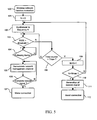
- the flow chart of Figure 5 shows the succession of operations carried out by a mobile terminal, in accordance with the present invention. Let Nmax be the number of frequencies used by the network and let Tmax be a period greater than the transmission period of a frame.
- the mobile terminal When the user decides to use the wireless network from the mobile terminal which accompanies him, he communicates this intention via the man-machine interface. The mobile terminal then receives this call (step 100).
- the mobile terminal monitors the RSSI signal which gives it information on the energy received at the antenna (test 103). If this energy remains below a predetermined threshold, it is considered that no signal is received.
- the threshold is determined from constraints of the network, such as the admitted useful range and the power at the transmitter as well as the minimum required signal to noise ratio.
- the terminal awaits the following frame (test 104) to demodulate the management channel of the network (step 105) until a complete beacon signal is obtained normally, that is to say a complete super frame (test 106).
- a complete beacon signal is obtained normally, that is to say a complete super frame (test 106).
- the connection-making procedure commences (step 107).
- the index N is incremented by one unit (step 109).
- the mobile terminal returns to step 102 and synthesizes the frequency corresponding to the index N +1.
- step 111 If the number N is greater than the number Nmax (test 110 positive), it is considered that the terminal has explored the whole time-frequency domain and has not found any pre-existing network there. It must then create this network. To do this, it transmits (step 111) a beacon signal in a time window and at a frequency of its choice, and waits for a connection to be established (step 112).
- the flow chart of Figure 6 shows the succession of operations carried out by an access point belonging to the potential network.
- the access point monitors the RSSI signal which gives it information on the energy received at the antenna (test 203). If this energy remains below a predetermined threshold, it is considered that no signal is received.
- the access point awaits the following frame (test 204) to demodulate the management channel of the network (step 205) until a complete beacon signal is obtained normally, that is to say a complete super frame (test 206). When this is obtained, a conventional connection-making procedure is commenced (step 207).
- the index N is incremented by one unit (step 209).
- the access point returns to step 202 and synthesizes the frequency corresponding to the index N + 1.
- the access point If the number N is greater than the number Nmax (test 210 positive), the access point returns to waiting for a beacon signal starting from step 201.
- the flow chart of Figure 7 shows the actual creation of the network, that is to say the first connection between access point and terminal.
- the steps corresponding to the access point (denoted AP in the drawing) are placed opposite those corresponding to the mobile terminal (denoted MT in the drawing).
- a time synchronization step 301 is carried out.
- the beacon channel indicates the frequency-time windows domain, and so the access point knows, after complete reception of a super frame, in which window and at which frequency the terminal will be listening.
- the access point transmits, in any one of the time windows, the fact that the terminal is listening (step 302).
- the mobile terminal carries out a test 351 which makes it possible to indicate the failure of the commencement of the network if for example no access point that is on has been detected after a period "max time".
- the transmission made by the access point at step 302 contains a specific so-called "challenge" message. It is a random number destined to be encoded with the use of a private key algorithm. Let there be two entities A and B wishing to authenticate each other. The entities A and B both know the same key and will use the same encryption algorithm. A sends a random number to B. A and B carry out a predefined calculation with this random number as operand. Next, B sends A the result of its calculation. A then compares this result with its own result and if the two are identical, A has authenticated B.
- This challenge is received at step 352 by the mobile terminal, which transmits the response to the challenge within the conjugate time window (or slot), followed by a new challenge.
- each communication between A and B uses a slot for the transmission from A to B and a slot for the transmission from B to A, and that these two slots are said to be conjugates of each other.
- This message is received by the access point at step 303.
- the mobile terminal sends the access point a message with the response to the challenge sent out by the access point as well as a challenge which it has created.
- the access point sends a message back to the mobile terminal with the response to the challenge sent out by the mobile terminal.
- the mobile terminal receives this response at step 354.
- the procedure has been simplified and account has not been taken of possible re-transmissions in case of error, the correct transmission of the data being ensured by the person skilled in the art knowing these methods.
- the access point having sent out a challenge and received a response, can authenticate the mobile terminal at step 306. If the authentication fails, the access point ceases all transmission at step 305a and remains silent, then resumes the process from the connector A 212, that is to say at step 201 of Figure 6 .
- the access point sends a message to the mobile terminal to inform it of this (step 307), then awaits the confirmation of its own authentication by the mobile terminal (step 308). If this confirmation is not received, as previously, the access point becomes silent (step 305b) then resumes the process in A (212), that is to say at step 201 of Figure 6 .
- the access point undertakes the transmission of the beacon signal.
- the verification of whether or not the access point belongs to the network is established at an authentication step 355.
- the process resumes at 351.
- the mobile terminal sends the access point a message of acceptance (step 356) and awaits confirmation of its own authentication by the access point (test 357). If this confirmation is not obtained, the process resumes at test 351.
- the mobile terminal stops transmitting the beacon signal, transmits that for signaling and receives the new beacon signal (step 358).
- the method then continues in conventional manner, as is summarized on the drawing by "ETC.” (step 359).
- the flow chart of Figure 8 shows the end of the temporary network.
- the access point continues to transmit a beacon signal for a predetermined time (step 401), in order permit the possibility of a terminal establishing a new connection.
- test 402 If a new connection is detected (test 402), the temporary network continues its existence in conventional manner, that is to say that connector B 312 of Figure 7 is proceeded to.
- the beacon signal is no longer transmitted (step 405) and the access point proceeds to the connector A 212, that is to say at step 201 of Figure 6 .
- the mobile terminal it is deactivated or reactivated by the user.
Landscapes
- Engineering & Computer Science (AREA)
- Computer Security & Cryptography (AREA)
- Computer Networks & Wireless Communication (AREA)
- Signal Processing (AREA)
- Mobile Radio Communication Systems (AREA)
- Communication Control (AREA)
Description
- The present invention relates to a method of communication in a network.
- The invention is in the field of wireless networks. These networks may be highly centralized, have one base station which manages the whole network and allocates network access to the various members, or else may be more distributed, that is to say that the decisions about network access are the result of one or more terminals deciding the rights of network access for themselves or for the others.
- These networks have in common the fact of having a channel for network management information, sometimes called the "beacon channel", and a channel for the user information, carrying data known as "payload data". The beacon channel is normally managed by the base station, which is in principle connected to a wired network of telephone or data type. The terminal is capable of transmitting a certain amount of information to the base station, in order to describe its own situation in relation to the network.
- Document
EP-A-0 490 441 discloses a method of operating a communications system in which secondary stations are able to roam in and out of respective radio coverage areas of a plurality of fixedly sited primary stations, such stations regularly transmitting idle beacon signals which are detectable by in range secondary stations operating in an idle locked state. - Document
WO-A-95 31080 - The commencement of the existence of a wireless network, on switching on the elements which make it up, is generally characterized by the presence of a beacon channel. Usually, this beacon channel is attributed to a base station which is an access point to a wired network.
- Among the existing systems, i.e. principally systems conforming to the DECT (Digital Enhanced Cordless Telecommunications) standard or to variants of it, two main categories may be identified: either a base station or an access point begins to transmit over a beacon channel as soon as it is turned on, or a mobile terminal that is turned on detects the lack of a beacon channel and declares itself to be a base station, whether or not it is an access point.
- However, such systems are not relevant in the case where the network under consideration is a mixed network, that is to say having a wired part and a wireless part, where the access points are multiple and linked to the same wired network. Such a mixed network is shown in
Figure 1 . The references MT0 and MT1 in the Figure represent mobile terminals and AP0, AP1, and AP2 represent access points linked to the same wired network. - The object of the present invention is to remedy the disadvantages described above.
- To that end, the present invention provides an access point in accordance with
claim 1 and a mobile terminal in accordance with claim 4. Other features are recited in the dependent claims. - Thus, at the initiative of a mobile terminal, a temporary wireless network is created between the pre-existing mobile terminals and access points. If there is no need for this network, no transmission takes place on the beacon channel. In other words, the network is only put into operation in the presence of a person operating his or her mobile terminal.
- Moreover, the temporary network is only maintained if necessary.
- An advantage of the present invention is that it makes it possible to save energy.
- Furthermore, the present invention makes it possible to avoid congesting the radio frequency space when there is no network user, since the temporary network is cut off in that case.
- The features of the dependent claims make it possible to guarantee not only that the mobile terminal is connected to an access point over which it has rights, but also that the access point is connected to a mobile terminal which has access rights to the network. This makes attempts at fraudulent access more difficult.
- In addition, as the transmission of a random number makes the connection non-deterministic from one occasion to the next, security is enhanced.
- Other aspects and advantages of the invention will emerge from a reading of the following detailed description of a particular embodiment, given by way of non-limiting example. The description refers to the accompanying drawings, in which:
-
Figure 1 , already described, is a diagram of a hybrid telecommunications network example, that is to say comprising a wired part and a wireless part, this network being adapted to implement the present invention; -
Figure 2 is a diagram of the architecture of a mobile station or a base station of the network ofFigure 1 , adapted to implement the present invention; -
Figure 3 is a diagram of the architecture of a network management module included in a mobile station or base station of the network ofFigure 1 ; -
Figure 4 shows the time-frequency domain used for communication in the network ofFigure 1 ; -
Figure 5 is a flow diagram illustrating the start of sequence for a mobile terminal, according to the present invention, in a particular embodiment; -
Figure 6 is a flow diagram illustrating the start of sequence for an access point, according to the present invention, in a particular embodiment; -
Figure 7 is a flow diagram illustrating the creation of a temporary network at the initiative of a mobile terminal, according to the present invention, in a particular embodiment; and -
Figure 8 is a flow diagram illustrating the end of a temporary network, according to the present invention, in a particular embodiment. - The object of the present invention is to create a beacon channel and thereby a wireless network, at the initiative of the mobile terminal, then to re-attribute this beacon channel to a point of access to the wired network, at the same time as the management of the access to the wireless network.
- In a network such as that of
Figure 1 described above, all the terminals, whether they be mobile terminals or base stations, are capable of transmitting and receiving information over at least one beacon channel, in addition to their minimum capability of receiving or transmitting over a signaling channel, and vice-versa. - The mobile items of equipment must be capable of measuring a period of time.
- The mobile terminals, as for the access points, possess an authentication system as well as an authentication key. This authentication key is held in a memory. This memory may be pre-loaded by the manufacturer or by a suitable system, as for example in a procedure for terminal - base station association by means of a cable, the manufacturer having pre-loaded the key in one of the two elements.
-
Figure 2 shows the simplified architecture of an element of a network of the type of that inFigure 1 . - A transmitter-
receiver 100 of the network comprises aradio module 200 and adata processing module 300 which contains a userdata management module 20 as well as anetwork management module 10. This management module may create a beacon channel and receive the information from the signaling channel, or else it may create the signaling information and receive the beacon channel. - The radio module contains a
frequency synthesizer 50 which is programmable by thenetwork management module 10. This frequency synthesizer, with the aid of amixer 60, makes it possible to modulate or demodulate the signals coming from - a
radio transmitter module 40, which transforms the binary signals output from themanagement modules - a
radio receiver module 30, which transforms the radio frequency signals into binary data understandable by themanagement modules - An
antenna 70 provides the interface with the outside. - The
receiver module 30 contains an RSSI (Received Signal Strength Indicator) 35 which sends an indication to themanagement module 10. -
Figure 3 shows a possible architecture for thenetwork management module 10. - This may be implemented with the use of conventional functions of a microcalculator. A
clock 370 makes it possible to have a time base and to create time-outs. - A
RAM memory 380 enables a large amount of data to be stored, aROM memory 330 enables storage of the program to be executed, while acentral processing unit 350 enables the sequential execution to be carried out of a certain number of instructions stored inROM 330 or inRAM 380. - A
random generator 360 which, as a variant, may be implemented purely in software form, is necessary. Aradio module interface 340 enables thefrequency synthesizer 50 to be driven. There may of course be an interface withother functions 310, whose processing it may be wished to integrate, as well as an interface with the wired orcabled network 320 if the member of the network under consideration is an access point. - As shown in
Figure 4 , which illustrates the time-frequency domain used by the network, the structure of the network is such that a frame comprises several time windows, it being possible to attribute each window to a member of the network for the transmission of a signal. For each new frame, a given member of the network systematically uses that window until the end of the connection. - In each window, network management information as well as user data information are transmitted. The entirety of the management information is transmitted over several frames. This group is called a "super frame".
- The flow chart of
Figure 5 shows the succession of operations carried out by a mobile terminal, in accordance with the present invention. Let Nmax be the number of frequencies used by the network and let Tmax be a period greater than the transmission period of a frame. - When the user decides to use the wireless network from the mobile terminal which accompanies him, he communicates this intention via the man-machine interface. The mobile terminal then receives this call (step 100).
- The terminal then initializes a register N with the value zero (step 101), then programs its frequency synthesizer to the frequency which corresponds to this index N = 0 (step 102).
- Then, for a period Tmax counted by a counter (test 108), the mobile terminal monitors the RSSI signal which gives it information on the energy received at the antenna (test 103). If this energy remains below a predetermined threshold, it is considered that no signal is received. The threshold is determined from constraints of the network, such as the admitted useful range and the power at the transmitter as well as the minimum required signal to noise ratio.
- If a signal is received, the terminal awaits the following frame (test 104) to demodulate the management channel of the network (step 105) until a complete beacon signal is obtained normally, that is to say a complete super frame (test 106). When this is obtained, the connection-making procedure commences (step 107).
- This branch has just described the case in which a network was pre-existing. The connection is then made in a conventional manner.
- If, during the whole period Tmax, the RSSI signal remained below the threshold (test 108 positive), then the index N is incremented by one unit (step 109).
- If the number N is below the value of Nmax, the mobile terminal returns to step 102 and synthesizes the frequency corresponding to the index N +1.
- If the number N is greater than the number Nmax (test 110 positive), it is considered that the terminal has explored the whole time-frequency domain and has not found any pre-existing network there. It must then create this network. To do this, it transmits (step 111) a beacon signal in a time window and at a frequency of its choice, and waits for a connection to be established (step 112).
- The flow chart of
Figure 6 shows the succession of operations carried out by an access point belonging to the potential network. - On turning on, the access point initializes a register N with the value zero (step 201), then programs its frequency synthesizer to the frequency which corresponds to this index N = 0 (step 202).
- Next, for a period Tmax (test 208), the access point monitors the RSSI signal which gives it information on the energy received at the antenna (test 203). If this energy remains below a predetermined threshold, it is considered that no signal is received.
- If a signal is received, the access point awaits the following frame (test 204) to demodulate the management channel of the network (step 205) until a complete beacon signal is obtained normally, that is to say a complete super frame (test 206). When this is obtained, a conventional connection-making procedure is commenced (step 207).
- If, during the whole period Tmax, the RSSI signal remained below the threshold (test 208 positive), then the index N is incremented by one unit (step 209).
- If the number N is below the value of Nmax, the access point returns to step 202 and synthesizes the frequency corresponding to the index N + 1.
- If the number N is greater than the number Nmax (test 210 positive), the access point returns to waiting for a beacon signal starting from
step 201. - The flow chart of
Figure 7 shows the actual creation of the network, that is to say the first connection between access point and terminal. For ease of understanding, the steps corresponding to the access point (denoted AP in the drawing) are placed opposite those corresponding to the mobile terminal (denoted MT in the drawing). - After connecting the access point, a
time synchronization step 301 is carried out. The beacon channel indicates the frequency-time windows domain, and so the access point knows, after complete reception of a super frame, in which window and at which frequency the terminal will be listening. - When this synchronization has been achieved, the access point transmits, in any one of the time windows, the fact that the terminal is listening (step 302).
- In parallel, while awaiting a connection, the mobile terminal carries out a
test 351 which makes it possible to indicate the failure of the commencement of the network if for example no access point that is on has been detected after a period "max time". - The transmission made by the access point at
step 302 contains a specific so-called "challenge" message. It is a random number destined to be encoded with the use of a private key algorithm. Let there be two entities A and B wishing to authenticate each other. The entities A and B both know the same key and will use the same encryption algorithm. A sends a random number to B. A and B carry out a predefined calculation with this random number as operand. Next, B sends A the result of its calculation. A then compares this result with its own result and if the two are identical, A has authenticated B. - This challenge is received at
step 352 by the mobile terminal, which transmits the response to the challenge within the conjugate time window (or slot), followed by a new challenge. - It should be recalled that each communication between A and B uses a slot for the transmission from A to B and a slot for the transmission from B to A, and that these two slots are said to be conjugates of each other.
- This message is received by the access point at
step 303. Atstep 353, the mobile terminal sends the access point a message with the response to the challenge sent out by the access point as well as a challenge which it has created. Atstep 304, the access point sends a message back to the mobile terminal with the response to the challenge sent out by the mobile terminal. - The mobile terminal receives this response at
step 354. Here, of course, the procedure has been simplified and account has not been taken of possible re-transmissions in case of error, the correct transmission of the data being ensured by the person skilled in the art knowing these methods. - The access point, having sent out a challenge and received a response, can authenticate the mobile terminal at
step 306. If the authentication fails, the access point ceases all transmission atstep 305a and remains silent, then resumes the process from theconnector A 212, that is to say atstep 201 ofFigure 6 . - If the authentication is successfully carried out, the access point sends a message to the mobile terminal to inform it of this (step 307), then awaits the confirmation of its own authentication by the mobile terminal (step 308). If this confirmation is not received, as previously, the access point becomes silent (
step 305b) then resumes the process in A (212), that is to say atstep 201 ofFigure 6 . - Otherwise, at a
step 309, the confirmation of the authentication having been received, the access point undertakes the transmission of the beacon signal. - Thus, a temporary network is created and its existence continues in a conventional manner, as shown in the drawing by "ETC." (step 311).
- For the mobile terminal, on reception from the access point of the response to the challenge coming from the mobile terminal, the verification of whether or not the access point belongs to the network is established at an
authentication step 355. - If the authentication fails, the process resumes at 351. When the authentication is achieved, the mobile terminal sends the access point a message of acceptance (step 356) and awaits confirmation of its own authentication by the access point (test 357). If this confirmation is not obtained, the process resumes at
test 351. - If the confirmation is obtained, then the mobile terminal stops transmitting the beacon signal, transmits that for signaling and receives the new beacon signal (step 358). The method then continues in conventional manner, as is summarized on the drawing by "ETC." (step 359).
- The flow chart of
Figure 8 shows the end of the temporary network. When the mobile terminal terminates the connection (step 400), the access point continues to transmit a beacon signal for a predetermined time (step 401), in order permit the possibility of a terminal establishing a new connection. - If a new connection is detected (test 402), the temporary network continues its existence in conventional manner, that is to say that
connector B 312 ofFigure 7 is proceeded to. - If the time limit for waiting for a new connection is exceeded (
test 401 positive), the beacon signal is no longer transmitted (step 405) and the access point proceeds to theconnector A 212, that is to say atstep 201 ofFigure 6 . As for the mobile terminal, it is deactivated or reactivated by the user. - The algorithms described above may be implemented either in the form of hardware or software.
Claims (6)
- An access point (AP0, AP1, AP2) in a wireless communication network comprising at least one mobile terminal (MT0, MT1), wherein said access point does not broadcast any beacon signal as long as no mobile terminal is operated in said network, said access point being characterized in that it comprises:means for detecting a beacon signal transmitted by a mobile terminal; andmeans for transmitting (309) a beacon signal in place of a given mobile terminal if said detecting means have detected that said given mobile terminal transmits a beacon signal.
- An access point according to claim 1, characterized in that it further comprises:means for triggering an authentication procedure with said given mobile terminal if said detecting means have detected that said given mobile terminal transmits a beacon signal, wherein said beacon signal transmitting means transmit (309) said beacon signal in place of said given mobile terminal only if said authentication procedure is successful.
- An access point according to claim 2, characterized in that it further comprises:means for sending (302) a random number to said given mobile terminal;means for performing a predetermined calculation based on said random number, so as to obtain a first result;means for receiving (303) from said given mobile terminal a second result of another predetermined calculation performed by said given mobile terminal based on said random number;means for comparing said first and second results; andmeans for authenticating (306) said given mobile terminal if said first and second results are identical.
- A mobile terminal (MT0, MT1) in a wireless communication network comprising at least one access point (APO, AP1, AP2), said mobile terminal being characterized in that it comprises:means for transmitting (111) a beacon signal;means for receiving (358) a beacon signal from a given access point; andmeans for stopping the transmission of said beacon signal after receipt of said beacon signal from said given access point.
- A mobile terminal according to claim 4, characterized in that it further comprises:means for carrying out (355) an authentication procedure with said given access point, wherein said stopping means stop the transmission of said beacon signal only if said authentication procedure is successful.
- A mobile terminal according to claim 5, characterized in that it further comprises:means for sending (353) a random number to said given access point;means for performing a predetermined calculation based on said random number, so as to obtain a second result;means for receiving (354) from said given access point a first result of another predetermined calculation performed by said given access point based on said random number;means for comparing said first and second results; andmeans for authenticating (356) said given access point if said first and second results are identical.
Applications Claiming Priority (2)
| Application Number | Priority Date | Filing Date | Title |
|---|---|---|---|
| FR0200175A FR2834595A1 (en) | 2002-01-08 | 2002-01-08 | COMMUNICATION METHOD IN A NETWORK |
| FR0200175 | 2002-01-08 |
Publications (2)
| Publication Number | Publication Date |
|---|---|
| EP1326466A1 EP1326466A1 (en) | 2003-07-09 |
| EP1326466B1 true EP1326466B1 (en) | 2009-09-09 |
Family
ID=8871199
Family Applications (1)
| Application Number | Title | Priority Date | Filing Date |
|---|---|---|---|
| EP02293254A Expired - Lifetime EP1326466B1 (en) | 2002-01-08 | 2002-12-27 | Method of communication in a network |
Country Status (5)
| Country | Link |
|---|---|
| US (1) | US7684785B2 (en) |
| EP (1) | EP1326466B1 (en) |
| JP (1) | JP3559786B2 (en) |
| DE (1) | DE60233631D1 (en) |
| FR (1) | FR2834595A1 (en) |
Families Citing this family (15)
| Publication number | Priority date | Publication date | Assignee | Title |
|---|---|---|---|---|
| US7099627B2 (en) * | 2003-06-11 | 2006-08-29 | Acco Brands Usa Llc | Systems and methods for a wireless network connection point locator |
| US20050054327A1 (en) * | 2003-09-04 | 2005-03-10 | David Johnston | System and associated methods to determine authentication priority between devices |
| WO2005031988A2 (en) * | 2003-09-23 | 2005-04-07 | Acco Brands, Inc. | Hand-held wireless network analyzer |
| KR20050051050A (en) * | 2003-11-26 | 2005-06-01 | 삼성전자주식회사 | Apparatus and method for informing user of wireless lan area |
| US7738877B2 (en) * | 2004-07-19 | 2010-06-15 | Cisco Technology, Inc. | Wireless network management with antenna control |
| US7263079B2 (en) * | 2004-07-30 | 2007-08-28 | Microsoft Corporation | System and methods for joining the correct wireless network |
| WO2007127312A2 (en) * | 2006-04-25 | 2007-11-08 | Interdigital Technology Corporation | High-throughput channel operation in a mesh wireless local area network |
| FR2906428A1 (en) * | 2006-09-26 | 2008-03-28 | Canon Kk | METHOD, DEVICE AND SOFTWARE APPLICATION FOR TRANSMITTING DATA PACKETS IN A COMMUNICATION SYSTEM. |
| US20080240146A1 (en) * | 2007-03-27 | 2008-10-02 | Harkirat Singh | System and method for wireless communication of uncompressed video having data transmission on a secondary low rate channel |
| US8150372B2 (en) * | 2007-09-28 | 2012-04-03 | Symbol Technologies, Inc. | Method and system for distributing data within a group of mobile units |
| JP5112229B2 (en) * | 2008-09-05 | 2013-01-09 | 株式会社エヌ・ティ・ティ・ドコモ | Distribution device, terminal device, system and method |
| EP2514169B1 (en) * | 2009-12-16 | 2019-03-13 | Nokia Technologies Oy | System, method, and apparatus for performing reliable network, capability, and service discovery |
| CN103533512A (en) * | 2013-09-17 | 2014-01-22 | 英华达(上海)科技有限公司 | Method, device and system for configuring and adding equipment into network group |
| JP6355425B2 (en) * | 2014-05-20 | 2018-07-11 | キヤノン株式会社 | System and control method thereof |
| CN104333890A (en) * | 2014-10-17 | 2015-02-04 | 小米科技有限责任公司 | Signal transmission control method, device and electronic equipment |
Family Cites Families (11)
| Publication number | Priority date | Publication date | Assignee | Title |
|---|---|---|---|---|
| GB2250892A (en) * | 1990-12-14 | 1992-06-17 | Philips Electronic Associated | A method of operating a radio communications system |
| AU2193395A (en) * | 1994-05-06 | 1995-11-29 | Motorola, Inc. | A method for establishing a communication link |
| US5835061A (en) * | 1995-06-06 | 1998-11-10 | Wayport, Inc. | Method and apparatus for geographic-based communications service |
| US6961762B1 (en) * | 2000-02-14 | 2005-11-01 | Sygate Technologies, Inc. | Automatic switching network points based on configuration profiles |
| US20020022483A1 (en) * | 2000-04-18 | 2002-02-21 | Wayport, Inc. | Distributed network communication system which allows multiple wireless service providers to share a common network infrastructure |
| WO2001093619A1 (en) * | 2000-05-31 | 2001-12-06 | Telefonaktiebolaget Lm Ericsson | A method and an arrangement for selecting a radio access unit in a radio communication system |
| FR2809897B1 (en) * | 2000-05-31 | 2005-04-29 | Gemplus Card Int | SECURE COMMUNICATION METHOD BETWEEN A NETWORK AND A CHIP CARD OF A TERMINAL |
| US6618584B1 (en) * | 2000-08-30 | 2003-09-09 | Telefonaktiebolaget Lm Ericsson (Publ) | Terminal authentication procedure timing for data calls |
| US7330472B2 (en) * | 2001-10-26 | 2008-02-12 | Sharp Laboratories Of America, Inc. | System and method for hybrid coordination in a wireless LAN |
| US7286671B2 (en) * | 2001-11-09 | 2007-10-23 | Ntt Docomo Inc. | Secure network access method |
| US20030125057A1 (en) * | 2001-12-27 | 2003-07-03 | Pesola Troy Raymond | System and method for automatic synchronization of managed data |
-
2002
- 2002-01-08 FR FR0200175A patent/FR2834595A1/en not_active Withdrawn
- 2002-12-27 EP EP02293254A patent/EP1326466B1/en not_active Expired - Lifetime
- 2002-12-27 DE DE60233631T patent/DE60233631D1/en not_active Expired - Lifetime
- 2002-12-31 US US10/331,477 patent/US7684785B2/en not_active Expired - Fee Related
-
2003
- 2003-01-08 JP JP2003002422A patent/JP3559786B2/en not_active Expired - Fee Related
Also Published As
| Publication number | Publication date |
|---|---|
| EP1326466A1 (en) | 2003-07-09 |
| US20030129966A1 (en) | 2003-07-10 |
| JP2003218983A (en) | 2003-07-31 |
| US7684785B2 (en) | 2010-03-23 |
| FR2834595A1 (en) | 2003-07-11 |
| DE60233631D1 (en) | 2009-10-22 |
| JP3559786B2 (en) | 2004-09-02 |
Similar Documents
| Publication | Publication Date | Title |
|---|---|---|
| US7684785B2 (en) | Method of communication in a network | |
| AU715234B2 (en) | Checking the presence of mobile stations communicating on a direct mode channel | |
| US5488649A (en) | Method for validating a communication link | |
| US4415770A (en) | Malfunction detection system for a mobile radio telephone system | |
| US7899404B2 (en) | Random access burst transmission scheme | |
| US5103445A (en) | Method of adapting a mobile radio communication system to traffic and performance requirements | |
| EP1191733A1 (en) | Automatic retransmission request (ARQ) mode transaction, where a base station determines the status of frames sent to a mobile station | |
| WO1995015666A1 (en) | Method for controlling a subscriber station in a radio system | |
| JP3787555B2 (en) | Communication method and access point device in network | |
| US6360091B1 (en) | Method and apparatus for establishing a communication link | |
| JPH02260719A (en) | Channel selection system for radio system | |
| JP2531254B2 (en) | Line connection method for distributed wireless system | |
| KR0135989B1 (en) | Method and apparatus for determining a communication system serving in an area where two or more communication systems are operating in combination | |
| EP0700627A1 (en) | Method for realizing ambience listening, and radio unit | |
| US6119002A (en) | Mobile station having methods and apparatus for performing neighbor channel measurements from analog control channel | |
| EP0583073B1 (en) | Cordless telephone system | |
| US7177291B1 (en) | Method for associating an apparatus in a communication network | |
| EP1738480B1 (en) | Device for use in a frequency hopping system | |
| CA2132497A1 (en) | Radio telecommunication apparatus | |
| KR100563703B1 (en) | Access Control System of Mobile Communication Terminal | |
| EP0788286B1 (en) | A radio handset and method of operation | |
| CN121284705A (en) | Distance measuring method | |
| GB2332823A (en) | Sequential selection of control channels for call attempt | |
| EP0843495A2 (en) | Method and system for the monitoring of the radio environment in a dect cordless system | |
| JPH08275247A (en) | Wide area mobile communication method |
Legal Events
| Date | Code | Title | Description |
|---|---|---|---|
| PUAI | Public reference made under article 153(3) epc to a published international application that has entered the european phase |
Free format text: ORIGINAL CODE: 0009012 |
|
| AK | Designated contracting states |
Designated state(s): AT BE BG CH CY CZ DE DK EE ES FI FR GB GR IE IT LI LU MC NL PT SE SI SK TR |
|
| AX | Request for extension of the european patent |
Extension state: AL LT LV MK RO |
|
| 17P | Request for examination filed |
Effective date: 20031201 |
|
| AKX | Designation fees paid |
Designated state(s): DE FI FR GB SE |
|
| 17Q | First examination report despatched |
Effective date: 20061229 |
|
| RIC1 | Information provided on ipc code assigned before grant |
Ipc: H04W 48/12 20090101AFI20090211BHEP |
|
| GRAP | Despatch of communication of intention to grant a patent |
Free format text: ORIGINAL CODE: EPIDOSNIGR1 |
|
| GRAS | Grant fee paid |
Free format text: ORIGINAL CODE: EPIDOSNIGR3 |
|
| GRAA | (expected) grant |
Free format text: ORIGINAL CODE: 0009210 |
|
| AK | Designated contracting states |
Kind code of ref document: B1 Designated state(s): DE FI FR GB SE |
|
| REG | Reference to a national code |
Ref country code: GB Ref legal event code: FG4D |
|
| REF | Corresponds to: |
Ref document number: 60233631 Country of ref document: DE Date of ref document: 20091022 Kind code of ref document: P |
|
| REG | Reference to a national code |
Ref country code: SE Ref legal event code: TRGR |
|
| PLBE | No opposition filed within time limit |
Free format text: ORIGINAL CODE: 0009261 |
|
| STAA | Information on the status of an ep patent application or granted ep patent |
Free format text: STATUS: NO OPPOSITION FILED WITHIN TIME LIMIT |
|
| 26N | No opposition filed |
Effective date: 20100610 |
|
| PGFP | Annual fee paid to national office [announced via postgrant information from national office to epo] |
Ref country code: FI Payment date: 20121203 Year of fee payment: 11 |
|
| PGFP | Annual fee paid to national office [announced via postgrant information from national office to epo] |
Ref country code: SE Payment date: 20121109 Year of fee payment: 11 |
|
| PGFP | Annual fee paid to national office [announced via postgrant information from national office to epo] |
Ref country code: FR Payment date: 20130118 Year of fee payment: 11 |
|
| REG | Reference to a national code |
Ref country code: SE Ref legal event code: EUG |
|
| PG25 | Lapsed in a contracting state [announced via postgrant information from national office to epo] |
Ref country code: SE Free format text: LAPSE BECAUSE OF NON-PAYMENT OF DUE FEES Effective date: 20131228 Ref country code: FI Free format text: LAPSE BECAUSE OF NON-PAYMENT OF DUE FEES Effective date: 20131227 |
|
| REG | Reference to a national code |
Ref country code: FR Ref legal event code: ST Effective date: 20140829 |
|
| PG25 | Lapsed in a contracting state [announced via postgrant information from national office to epo] |
Ref country code: FR Free format text: LAPSE BECAUSE OF NON-PAYMENT OF DUE FEES Effective date: 20131231 |
|
| PGFP | Annual fee paid to national office [announced via postgrant information from national office to epo] |
Ref country code: GB Payment date: 20161230 Year of fee payment: 15 |
|
| PGFP | Annual fee paid to national office [announced via postgrant information from national office to epo] |
Ref country code: DE Payment date: 20161231 Year of fee payment: 15 |
|
| REG | Reference to a national code |
Ref country code: DE Ref legal event code: R119 Ref document number: 60233631 Country of ref document: DE |
|
| GBPC | Gb: european patent ceased through non-payment of renewal fee |
Effective date: 20171227 |
|
| PG25 | Lapsed in a contracting state [announced via postgrant information from national office to epo] |
Ref country code: DE Free format text: LAPSE BECAUSE OF NON-PAYMENT OF DUE FEES Effective date: 20180703 |
|
| PG25 | Lapsed in a contracting state [announced via postgrant information from national office to epo] |
Ref country code: GB Free format text: LAPSE BECAUSE OF NON-PAYMENT OF DUE FEES Effective date: 20171227 |