EP1326450A1 - Method and apparatus for detecting block-structured artifacts - Google Patents
Method and apparatus for detecting block-structured artifacts Download PDFInfo
- Publication number
- EP1326450A1 EP1326450A1 EP01130689A EP01130689A EP1326450A1 EP 1326450 A1 EP1326450 A1 EP 1326450A1 EP 01130689 A EP01130689 A EP 01130689A EP 01130689 A EP01130689 A EP 01130689A EP 1326450 A1 EP1326450 A1 EP 1326450A1
- Authority
- EP
- European Patent Office
- Prior art keywords
- value
- pixel
- video frame
- highest
- values
- Prior art date
- Legal status (The legal status is an assumption and is not a legal conclusion. Google has not performed a legal analysis and makes no representation as to the accuracy of the status listed.)
- Withdrawn
Links
- 238000000034 method Methods 0.000 title claims abstract description 40
- 238000001514 detection method Methods 0.000 claims description 19
- 238000007781 pre-processing Methods 0.000 claims description 11
- 238000004590 computer program Methods 0.000 claims description 5
- 230000002596 correlated effect Effects 0.000 claims description 4
- 230000003247 decreasing effect Effects 0.000 claims description 3
- 230000002708 enhancing effect Effects 0.000 claims description 2
- 239000003638 chemical reducing agent Substances 0.000 abstract description 2
- 230000000903 blocking effect Effects 0.000 description 1
- 238000007906 compression Methods 0.000 description 1
- 230000008021 deposition Effects 0.000 description 1
Images


Classifications
-
- H—ELECTRICITY
- H04—ELECTRIC COMMUNICATION TECHNIQUE
- H04N—PICTORIAL COMMUNICATION, e.g. TELEVISION
- H04N19/00—Methods or arrangements for coding, decoding, compressing or decompressing digital video signals
- H04N19/85—Methods or arrangements for coding, decoding, compressing or decompressing digital video signals using pre-processing or post-processing specially adapted for video compression
- H04N19/86—Methods or arrangements for coding, decoding, compressing or decompressing digital video signals using pre-processing or post-processing specially adapted for video compression involving reduction of coding artifacts, e.g. of blockiness
-
- H—ELECTRICITY
- H04—ELECTRIC COMMUNICATION TECHNIQUE
- H04N—PICTORIAL COMMUNICATION, e.g. TELEVISION
- H04N19/00—Methods or arrangements for coding, decoding, compressing or decompressing digital video signals
- H04N19/85—Methods or arrangements for coding, decoding, compressing or decompressing digital video signals using pre-processing or post-processing specially adapted for video compression
- H04N19/86—Methods or arrangements for coding, decoding, compressing or decompressing digital video signals using pre-processing or post-processing specially adapted for video compression involving reduction of coding artifacts, e.g. of blockiness
- H04N19/865—Methods or arrangements for coding, decoding, compressing or decompressing digital video signals using pre-processing or post-processing specially adapted for video compression involving reduction of coding artifacts, e.g. of blockiness with detection of the former encoding block subdivision in decompressed video
Definitions
- the invention relates to a method for detecting block-structured artifacts and an apparatus used for performing said method.
- MPEG-compression algorithm is a very common and frequently used standard.
- an 8 by 8 pixel block artifact pattern appears, especially in the case of high motion within the images and/or low bit rate image streams.
- BNR block noise reducer
- the present invention provides a method for detecting block-structured artifacts according to claim 1. Further, the present invention provides an apparatus for detecting block-structured artifacts according to claim 10. Last, a computer program product according to claim 20 is provided. Further features and embodiments are respectively defined in respective subclaims.
- a method for detecting block-structured artifacts within a video frame comprises the following steps:
- Step a) is needed if the vertical positions of said artifacts have to be determined, whereas step b) is needed if the horizontal positions of said artifacts have to be determined, step c) is always needed.
- the method described above in particular provides an "Automatic MPEG Block Structure Phase Detector" generating in real time reliable information on the existence and the position of block artifacts occurring during an MPEG decoding process.
- video frame means in particular digital image data (the video signal).
- a second highest value of the PTV i values/a second highest value of the PTH i values are determined. Then, the highest PTV i /PTH i values and the second highest PTV i /PTH i values are compared with each other, respectively. If it is found that a difference between the highest PTV i /PTH i values and the second highest PTV i /PTH i values exceeds a certain threshold value, respectively, it is determined that the highest PTV i /PTH i values correspond to respective vertical/horizontal positions of artifacts, i.e. it is decided that artifacts are present.
- the threshold value may be dynamically set in depedence of previous generated/stored artifact information.
- Artifact information means all kind of information correlated to artifacts, for example video frame, motion data related to said video frames, artifact positions, and the like.
- the sensivity of the above-described filter mechanism can be adapted to changing demands.
- the threshold value may be increased if no artifacts have been detected in previous processed video frames, and may be decreased if artifacts have been detected in previous processed video frames.
- a detection of artifacts itself can be regarded as a generation of artifact information which may be stored and used for processing succeeding video frames.
- the inventive method preferably is applicated to a stream of video frames, i. e. to a sequence of video frames.
- one single (“isolated") video frame may be subjected to artifact detecting.
- concrete artifact positions may also be stored as artifact information for further use. If, for example, in different video frames an artifact has been detected for a long period of time at the same position, respectively, it is likely that in succeeding video frames artifacts will appear at that position, too. Therefore, all detected artifact positions may be compared with the positions of artifacts detected before. Then, for example, a detection of an artifact may not be considered to be valid if a positional deviation between the position of a current detected artifact and the positions of previous detected artifacts exceeds a certain threshold value.
- motion associated with a current video frame is detected by comparing luminance values of the current video frame with luminance values of at least the previous video frame. Then, the process of detecting artifacts may be deactivated for the time in which no motion is detected. This is due to the fact that artifacts during an MPEG-decoding process occur especially in the case when motion is present within the video frame.
- the above-described step provides a very effective means to save computational resources.
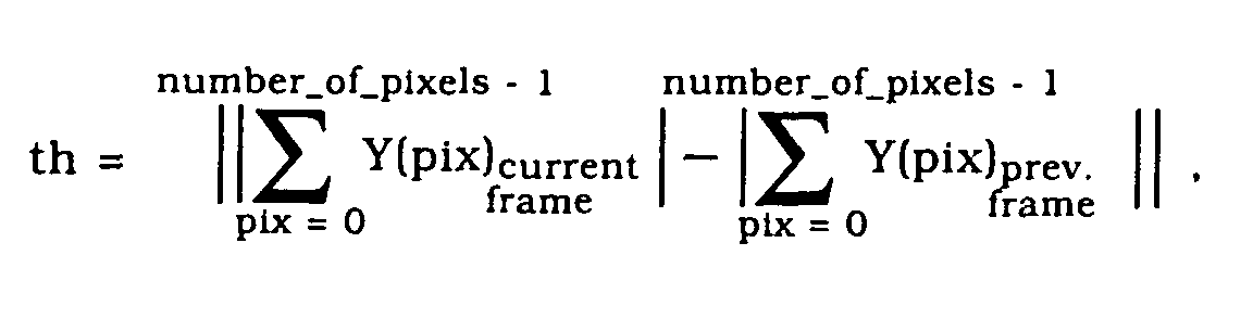
- the motion detecting process is done according to the following equation: wherein number_of_pixels is the total number of pixels within a respective frame, pix is a pixel position index, and Y(pix) is a luminance value of a pixel at a position indicated by pix. If the value th exceeds a certain motion threshold value, it is decided that motion is present.
- the above-described method is in particular suitable to be used in conjunction with MPEG-video frames, but may also be applied to any other standard for compressing/decompressing digital video data, for example JPEG.
- the term "artifact pixel periodicy value" pv/ph is to be understood as the number of pixels after which the artifact occurs again. For example, if an artifact occurs every 8 pixels in a pixel line, pv is 8. pv and/or ph are preferably 8, if the above-described method is used in conjunction with MPEG-video frames.
- the video frame is preprocessed such that borderlines of objects contained within the video frames are enhanced, wherein the preprocessing is done before applying said searching process for artifacts as described above.
- the method as described above has the following advantages:
- the detection reliability is very high; the state of the art detects blocking artifact based on the analysis of only a single video frame at a time, which might lead to an unreliable detection especially when the video frame contains horizontal and vertical lines.
- the invention takes into consideration existence of motion between two succeeding video frames and uses a decision mechanism that provides information on the existence and deposition of the grids (the structure of all block border lines creates the grid).
- the invention further provides an apparatus for detecting block-structured artifacts within a video frame, which comprises:
- Feature a) is needed if the vertical positions of said artifacts have to be determind, whereas feature b) is needed if the horizontal positions of said artifacts have to be determined, feature c) is always needed.
- the apparatus described above in particular provides an "Automatic MPEG Structure Phase Detector" generating in real time reliable information on the existence and the positions of block artifacts occurring during an MPEG-decoding process.
- the processing module comprises a first/second vertical peak detecting unit being connected to the vertical sum module for detecting the highest value/a second highest value of the PTV i values.
- the processing module may comprise a first/second horizontal peak detecting unit being connected to the horizontal sum module for detecting the highest value/a second highest value of the PTH i values.
- the processing module may further comprise a decision unit being connected to the first/second vertical peak detecting unit and first/second horizontal peak detecting unit for processing the highest and/or second highest PTV i /PTH i values supplied by the first/second vertical peak detecting unit and said first/second horizontal peak detecting unit in dependence of artifact information in order to decide if artifacts are present within the video frame.
- a decision unit being connected to the first/second vertical peak detecting unit and first/second horizontal peak detecting unit for processing the highest and/or second highest PTV i /PTH i values supplied by the first/second vertical peak detecting unit and said first/second horizontal peak detecting unit in dependence of artifact information in order to decide if artifacts are present within the video frame.
- the apparatus comprises a motion detection unit being connected to the decision unit to detect motion within the video frame currently processed by the vertical/horizontal sum modules, and to supply a motion detection result to the decision unit.
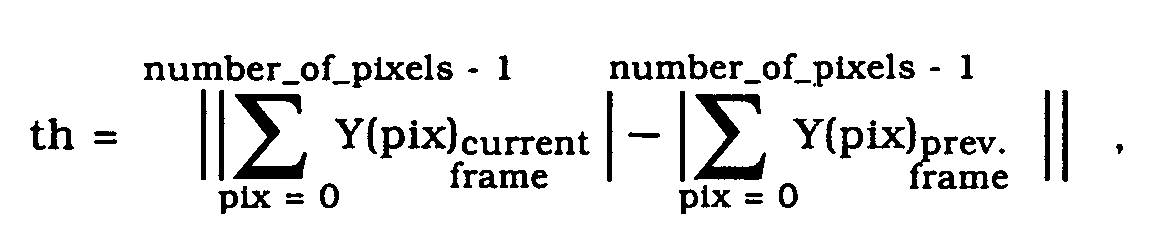
- the motion detection unit detects motion preferably according to the following equation: wherein number_of_pixels is the total number of pixels within a respective frame, pix is a pixel position index, and Y(pix) is a luminance value of a pixel at a position indicated by pix. If the value th exceeds a certain motion threshold value, it is decided that motion is present.
- a preprocessing module being connected to the vertical/horizontal sum module and/or to the motion detection unit for enhancing borderlines of objects contained within the video frame before supplying a preprocessed video frame to the vertical/horizontal sum modules.
- the apparatus may further comprise a storage means included within the decision unit for storing PTV i /PTH i values and/or other artifact information.
- a history of artifacts occurred within previous video frames can be used to process the current video frame.
- the decision unit may further comprise a function for calculating a difference between the highest PTV i /PTH i values and said second highest PTV i /PTH i values, respectively, and for outputting a "positive" artifact detection result if the difference exceeds a certain threshold value.
- the decision unit may further comprise a function for dynamically setting the threshold value in depencence of existing artifact information.
- the invention further provides a computer program product comprising computer program means adapted for performing the steps of the inventive method when it is executed on a computer, a digital signal processor or the like.
- An apparatus for detecting block-structured artifacts 1 comprises a preprocessing module 2, a vertical sum module 3, a horizontal sum module 4, a processing module 5, and a motion detection module 6.
- the processing module 5 comprises a first vertical peak detecting unit 7, a second vertical peak detecting unit 8, a first horizontal peak detecting unit 9, a second horizontal peak detecting unit 10, and a decision unit 11.
- An output of the preprocessing module 2 is connected to both an input of the vertical sum module 3 and an input of the horizontal sum module 4.
- An output of the vertical sum module 3 is connected to both an input of the first vertical peak detecting unit 7, and an input of the second vertical peak detecting unit 8.
- An output of the horizontal sum module 4 is connected to both an input of the first horizontal peak detecting unit 9 and an input of the second horizontal peak detecting unit 10. Respective outputs of the first/second vertical peak detecting units 7, 8 and the first/second horizontal peak detecting units 9, 10 are connected with the decision unit 11. Further, an output of the motion detection module 6 is connected with the decision unit 11.
- a video frame of the video frame stream is supplied to both the preprocessing module 2 and the motion detection module 6.
- the preprocessing module 2 preferably a luminance part of a video field of the video frame is processed to enhance borderlines of graphical objects contained within the video frame including the artifacts (for example grid lines between blocks).
- An enhanced video frame is outputted by the preprocessing module 2 and supplied to both the input of the vertical sum module 3 and the horizontal sum module 4.
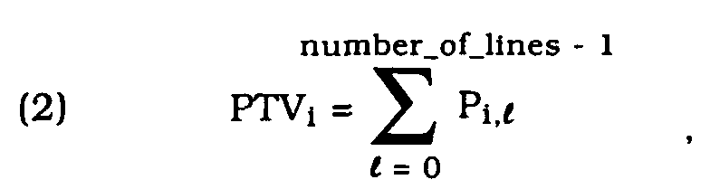
- pv vertical luminance levels P i,l are calculated according to the following equation: wherein pv is an artifact pixel periodicy value (here 8), i is an index running from zero to (pv-1), 1 is a pixel line index running from 0 to (number_of_lines-1), wherein number_of_lines is the total number of pixel lines 21 0 to 21 6 (here 7), Y(x) is the luminance value of a pixel at a position x within a pixel line, and line_length is the total number of pixels of a single pixel line.
- pv is an artifact pixel periodicy value (here 8)
- i is an index running from zero to (pv-1)
- 1 is a pixel line index running from 0 to (number_of_lines-1)
- number_of_lines is the total number of pixel lines 21 0 to 21 6 (here 7)
- Y(x) is the luminance value of a pixel at a
- the artifact pattern is a pixel line which is repeated at every interval of 8 pixels, i.e. in the pixel column 22 2 , 22 10 and 22 18 .
- the luminance values of the pixels of the pixel columns 22 2 , 22 10 and 22 18 are summed up to yield the value PTV 2 .
- the luminance values of all pixels of the pixel columns 22 0 , 22 8 and 22 16 are summed up to yield the value PTV 0 .
- the values PTV 0 to PTV 7 are supplied to both the first vertical peak detecting unit 7 and the second vertical peak detecting unit 8. The same is done in an analogous manner for the PTH i values which are supplied from the horizontal sum module 4 to both the first horizontal peak detecting unit 9 and the second horizontal peak detecting unit 10.
- the first vertical peak detecting unit 7 it is determined that the highest among the PTV i values is the value PTV 2 .
- the second vertical peak detecting unit 8 it is determined that the second highest PTV i value is value PTV 1 (here it is assumed that PTV 1 is the second highest PTV i value).
- the values PTV 1 and PTV 2 are supplied to the decision unit 11 where these two values are compared with each other. If the difference between these values exceeds a certain threshold value, it is decided that there is an artifact within the video frame 20.
- the positions of these artifacts are indicated by the highest PTV i value, i.e. here PTV 2 (the number of the "artifact column” is given by the index number of the highest PTV i value; here, the highest PTV i value is PTV 2 , thus the "artifact column” is pixel column number 2). Since the artifact pixel periodicy value is 8 the artifact is repeated every 8 pixels. Thus, the positions of the artifacts are located in pixel columns 22 2 , 22 10 and 22 18 . If the threshold value is not exceeded, it is determined that there is no artifact.
- the threshold value may be dynamically set in dependence of previous generated/stored artifact information. This information may for example include previous phase information or a motion between two consecutive video frames. The threshold value may for example be increased if no artifacts have been detected before, and decreased if artifacts have been detected.
- the motion detection module 6 detects motion of the current video frame supplied to its input by comparing luminance values of the current video frame with luminance values of at least the previous video frame. A respective motion detection result is supplied to the decision unit 11.
- the decision unit may deactivate the rest of the processing unit 5, i.e. the first/second peak detecting units 7 to 10 as well as the vertical sum module 3, the horizontal sum module 4, and the preprocessing module 2 until the motion detecting module 6 supplies a "positive" motion detection result telling the decision unit 11 that motion is again present within the current video frame of the video frame stream.
- the motion detecting process is done by comparing an absolute value th of a difference given by equation: with a certain motion threshold value, wherein number_of_pixels is the total number of pixels within a respective frame, pix is a pixel position index, and Y(pix) is a luminance value of a pixel at a position indicated by pix. If the value th exceeds said motion threshold value, it is decided that motion is present. In other words, an accumulated absolute value of all the pixels' luminance in the current video frame is substracted from an accumulated absolute value of all pixels' luminance in a previous video frame to obtain an absolute value th of a resulting difference, and this absolute value th is compared against said motion threshold value.
- the decision unit 11 outputs four signals: Ph0 is the highest PTHi value, Ph1 is the second highest PTHi value, Pv0 is the highest PTVi value, Pv1 is the second highest PTVi value, and BS is a block signal indicating if artifacts are present or not.
- the reliability of detecting MPEG artifact blocks according to the inventive method is higher than those of the state of the art.
- the inventive method can be applied both to one-dimensional and two-dimensional video frames.
Landscapes
- Engineering & Computer Science (AREA)
- Multimedia (AREA)
- Signal Processing (AREA)
- Compression Or Coding Systems Of Tv Signals (AREA)
Abstract
Description

pv is an artifact pixel periodicy value, i is an index running from 0 to (pv-1), 1 is a pixel line index running from 0 to (number_of_lines-1), wherein number_of_lines is the total number of pixel lines, Y(x) is the luminance value of a pixel at a position x within a pixel line, and line_length is the total number of pixels of a single pixel line,
calculating pv sums of the vertical luminance levels PTVi according to the following equation:
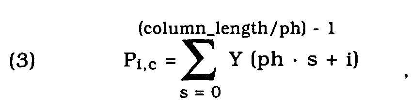
ph is an artifact pixel periodicy value, i is an index running from 0 to (ph-1), c is a pixel column index running from 0 to (number_of_columns-1), wherein number_of_columns is the total number of pixel columns, Y(x) is the luminance value of a pixel at a position x within a pixel column, and column_length is the total number of pixels of a single pixel column,
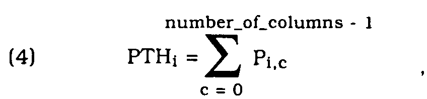
calculating ph sums of the horizontal luminance levels PTHi according to the following equation:

- calculating for each pixel line within the video frame pv vertical luminance
levels Pi,l according to following equation:

pv is an artifact pixel periodicy value, i is an index running from 0 to (pv-1), 1 is a pixel line index running from 0 to (number_of_lines-1), wherein number_of_lines is the total number of pixel lines, Y(x) is the luminance value of a pixel at a position x within a pixel line, and line_length is the total number of pixels of a single pixel line,
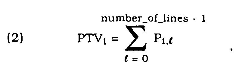
- calculating pv sums of the vertical luminance levels PTVi according to
the following equation:
and/or
- calculating for each pixel column within the video frame ph horizontal
luminance levels Pi,c according to following equation:

- calculating ph sums of the horizontal luminance levels PTHi according to
the following equation:
and


- Fig. 1
- shows a preferred embodiment of the architecture of the appapratus according to the present invention;
- Fig. 2
- shows a schematic drawing of a video frame illustrating the principle of a vertical summing process according to the present invention.


Claims (20)
- Method for detecting block strucured artifacts within a video frame (20), comprising the following steps:a) calculating for each pixel line (210 to 216) within said video frame (20) pv vertical luminance levels Pi,l according to following equation:wherein

pv is an artifact pixel periodicy value, i is an index running from 0 to pv-1, 1 is a pixel line index running from 0 to number_of_lines-1, wherein number_of_lines is the total number of pixel lines (210 to 216), Y(x) is the luminance value of a pixel at a position x within a pixel line (210 to 216), and line_length is the total number of pixels of a single pixel line (210 to 216),
calculating pv sums of said vertical luminance levels PTVi according to the following equation:and/or b) calculating for each pixel column (220 to 2219) within said video frame (20) ph horizontal luminance levels Pi,c according to following equation:wherein ph is an artifact pixel periodicy value, i is an index running from 0 to ph-1, c is a pixel column index running from 0 to number_of_columns-1, wherein number_of_columns is the total number of pixel columns (220 to 2219), Y(x) is the luminance value of a pixel at a position x within a pixel column (220 to 2219), and column_length is the total number of pixels of a single pixel column (220 to 2219).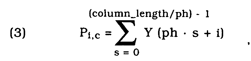
calculating ph sums of said horizontal luminance levels PTHi according to the following equation:and c) determining a highest value of said PTVi values and/or a highest value of said PTHi values, and determining vertical and/or horizontal positions of said artifacts within said video frame (20) on the basis of said highest PTVi value and/or said highest PTHi value.
 - Method according to claim 1, characterized by determining a second highest value of said PTVi values and a second highest value of said PTHi values, and determining that said highest value of said PTVi values and said highest value of said PTHi values respectively represent vertical and/or horizontal positions of said artifacts if a difference between said second highest value of said PTVi values and of said PTHi values respectively exceeds a certain threshold value.
- Method according to claim 2, characterized in that said threshold value is dynamically set in dependence of previous generated block artifact information.
- Method according to claim 3, characterized by increasing said threshold value if no artifacts have been detected, and decreasing said threshold value if artifacts have been detected.
- Method according to anyone of the claims 1 to 4, characterized by detecting motion associated with a current video frame (20) by comparing luminance values of said current video frame (20) with luminance values of at least the previous video frame (20), and temporarily deactivating said process of detecting artifacts during the time in which no motion is detected.
- Method according to claim 5, characterized in that said motion detecting process is done according to the following equation:wherein number_of_pixels is the total number of pixels within a respective video frame (20), pix is a pixel position index, and Y(pix) is a luminance value of a pixel at a position indicated by pix, wherein, by the above formula, an accumulated absolute value of all the pixels' luminance in a current video frame is substracted from an accumulated absolute value of all pixels' luminance in a previous video frame to obtain an absolute value th of of a resulting difference, wherein said absolute value th is compared against a motion threshold value, and it is decided that motion is present if said absolute value th of said resulting difference is higher than said motion threshold value.
- Method according to anyone of the claims 1 to 6, characterized by using said method to detect block strucured artifacts within MPEG video frames (20).
- Method according to anyone of the claims 1 to 7, characterized in that said artifact pixel periodicy values pv and/or ph is 8.
- Method according to anyone of the claims 1 to 8, characterized by preprocessing the video frame (20) such that borderlines of objects contained within the video frame (20) are enhanced, said preprocessing being done before searching for artifacts.
- Apparatus (1) for detecting block structured artifacts within a video frame (20), comprising:a) a vertical sum module (3) for:whereincalculating for each pixel line (210 to 216) within said video frame (20) pv vertical luminance levels Pi,l according to following equation:

pv is an artifact pixel periodicy value, i is an index running from 0 to pv-1, 1 is a pixel line index running from 0 to number_of_lines-1, wherein number_of_lines is the total number of pixel lines (210 to 216), Y(x) is the luminance value of a pixel at a position x within a pixel line (210 to 216), and line_length is the total number of pixels of a single pixel line (210 to 216),calculating pv sums of said vertical luminance levels PTVi according to the following equation:and/or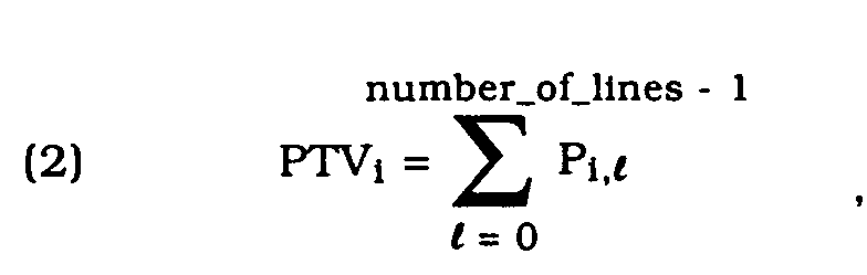 b) a horizontal sum module (4) for:wherein ph is an artifact pixel periodicy value, i is an index running from 0 to ph-1, c is a pixel column index running from 0 to number_of_columns-1, wherein number_of_columns is the total number of pixel columns (220 to 2219), Y(x) is the luminance value of a pixel at a position x within a pixel column (220 to 2219), and column_length is the total number of pixels of a single pixel column (220 to 2219).calculating for each pixel column (220 to 2219) within said video frame (20) ph horizontal luminance levels Pi,c according to following equation:
 calculating ph sums of said horizontal luminance levels PTHi according to the following equation:and
 c) a processing module (5) being connected to said a vertical sum module (3) and said horizontal sum module (4) for determining a highest value of said PTVi values and a highest value of said PTHi values, and for determining vertical and/or horizontal positions of said artifacts within said video frame (20) on the basis of said highest PTVi value and/or said highest PTHi value.
 - Apparatus (1) according to claim 10, characterized in that said processing module (5) comprises a first/second vertical peak detecting unit (7, 8) being connected to said vertical sum module (4) for detecting said highest value/a second highest value of said PTVi values.
- Apparatus (1) according to anyone of the claims 10 to 11, characterized in that said processing module (5) comprises a first/second horizontal peak detecting unit (9, 10) being connected to said horizontal sum module (4) for detecting said highest value/a second highest value of said PTHi values.
- Apparatus (1) according to claim 12, characterized in that said processing module (5) comprises a decision unit (11) being connected to said first/second vertical peak detecting unit (7, 8) and said first/second horizontal peak detecting unit (9, 10) for processing said highest and/or second highest PTVi/PTHi values supplied by said first/second vertical peak detecting unit (7, 8) and said first/second horizontal peak detecting unit (9, 10) in dependence of artifact correlated information in order to decide if artifacts are present within said video frame (20).
- Apparatus (1) according to claim 13, characterized by a motion detection module (6) being connected to said decision unit (11) to detect motion within said video frame (20), and to supply a motion detection result to said decision unit (11).
- Apparatus (1) according to anyone of the claims 10 to 14, characterized by a preprocessing module (2) being connected to said vertical/horizontal sum module (3, 4) for enhancing borderlines of objects contained within said video frame (20) before supplying a preprocessed video frame (20) to said vertical/horizontal sum modules (3, 4).
- Apparatus (1) according to anyone of the claims 13 to 15, characterized in that said decision unit comprises a storage means for storing PTVi/PTHi values and/or other artifact correlated information.
- Apparatus (1) according to anyone of the claims 13 to 16, characterized in that said decision unit (11) comprises a function for calculating a difference between said highest PTVi/PTHi value and said second highest PTVi/PTHi value, respectively, and for outputting an artifact detection result if said difference exceeds a certain threshold value.
- Apparatus (1) according to claim 17, characterized in that said decision unit (11) comprises a function for dynamically setting said threshold value in dependence of existing artifact correlated information.
- Apparatus (1) according to claim 18, characterized in that said motion detection module (6) detects motion according to the following equation:wherein number_of_pixels is the total number of pixels within a respective frame (20), pix is a pixel position Index, and Y(pix) is a luminance value of a pixel at a position indicated by pix, wherein, by the above formula, an accumulated absolute value of all the pixels' luminance in a current video frame is substracted from an accumulated absolute value of all pixels' luminance in a previous video frame to obtain an absolute value th of a resulting difference, wherein said absolute value th is compared against a motion threshold value, and it is decided that motion is present if said absolute value th of said resulting difference is higher than said motion threshold value.
- Computer program product comprising computer program means adapted to perform any step of the method of the claims 1 to 9 when it is executed on a computer, a digital signal processor or the like.
Priority Applications (1)
| Application Number | Priority Date | Filing Date | Title |
|---|---|---|---|
| EP01130689A EP1326450A1 (en) | 2001-12-21 | 2001-12-21 | Method and apparatus for detecting block-structured artifacts |
Applications Claiming Priority (1)
| Application Number | Priority Date | Filing Date | Title |
|---|---|---|---|
| EP01130689A EP1326450A1 (en) | 2001-12-21 | 2001-12-21 | Method and apparatus for detecting block-structured artifacts |
Publications (1)
| Publication Number | Publication Date |
|---|---|
| EP1326450A1 true EP1326450A1 (en) | 2003-07-09 |
Family
ID=8179657
Family Applications (1)
| Application Number | Title | Priority Date | Filing Date |
|---|---|---|---|
| EP01130689A Withdrawn EP1326450A1 (en) | 2001-12-21 | 2001-12-21 | Method and apparatus for detecting block-structured artifacts |
Country Status (1)
| Country | Link |
|---|---|
| EP (1) | EP1326450A1 (en) |
Cited By (1)
| Publication number | Priority date | Publication date | Assignee | Title |
|---|---|---|---|---|
| WO2004014084A1 (en) * | 2002-07-31 | 2004-02-12 | Koninklijke Philips Electronics N.V. | Dynamic detection of blocking artefacts |
Citations (5)
| Publication number | Priority date | Publication date | Assignee | Title |
|---|---|---|---|---|
| FR2769452A1 (en) * | 1997-10-06 | 1999-04-09 | Telediffusion Fse | Method of spatial synchronisation of coded video image |
| EP0998149A1 (en) * | 1998-10-27 | 2000-05-03 | France Telecom | Method for controlling the quality of broadcast digital images |
| WO2001020912A1 (en) * | 1999-09-14 | 2001-03-22 | Koninklijke Philips Electronics N.V. | Method and device for identifying block artifacts in digital video pictures |
| US6219450B1 (en) * | 1998-11-13 | 2001-04-17 | Xerox Corporation | Blocking signature detection for identification JPEG images |
| EP1168823A2 (en) * | 2000-06-29 | 2002-01-02 | Eastman Kodak Company | A method of determining the extent of blocking artifacts in a digital image |
-
2001
- 2001-12-21 EP EP01130689A patent/EP1326450A1/en not_active Withdrawn
Patent Citations (5)
| Publication number | Priority date | Publication date | Assignee | Title |
|---|---|---|---|---|
| FR2769452A1 (en) * | 1997-10-06 | 1999-04-09 | Telediffusion Fse | Method of spatial synchronisation of coded video image |
| EP0998149A1 (en) * | 1998-10-27 | 2000-05-03 | France Telecom | Method for controlling the quality of broadcast digital images |
| US6219450B1 (en) * | 1998-11-13 | 2001-04-17 | Xerox Corporation | Blocking signature detection for identification JPEG images |
| WO2001020912A1 (en) * | 1999-09-14 | 2001-03-22 | Koninklijke Philips Electronics N.V. | Method and device for identifying block artifacts in digital video pictures |
| EP1168823A2 (en) * | 2000-06-29 | 2002-01-02 | Eastman Kodak Company | A method of determining the extent of blocking artifacts in a digital image |
Non-Patent Citations (4)
| Title |
|---|
| CHEN J-L ET AL: "An efficient algorithm for form structure extraction using strip projection", PATTERN RECOGNITION, PERGAMON PRESS INC. ELMSFORD, N.Y, US, vol. 31, no. 9, 1 September 1998 (1998-09-01), pages 1353 - 1368, XP004127719, ISSN: 0031-3203 * |
| DERVIAUX C ET AL: "Blocking artifact reduction of DCT coded image sequences using a visually adaptive postprocessing", PROCEEDINGS OF THE INTERNATIONAL CONFERENCE ON IMAGE PROCESSING (ICIP) LAUSANNE, SEPT. 16 - 19, 1996, NEW YORK, IEEE, US, vol. 1, 16 September 1996 (1996-09-16), pages 5 - 8, XP010202580, ISBN: 0-7803-3259-8 * |
| SUTHAHARAN S: "Lspl infin//-based distortion measure for blocking artifacts in digital video", DEVICES, CIRCUITS AND SYSTEMS, 1998. PROCEEDINGS OF THE 1998 SECOND IEEE INTERNATIONAL CARACAS CONFERENCE ON ISLA DE MARGARITA, VENEZUELA 2-4 MARCH 1998, NEW YORK, NY, USA,IEEE, US, 2 March 1998 (1998-03-02), pages 235 - 238, XP010295671, ISBN: 0-7803-4434-0 * |
| TAN K T ET AL: "Measuring blocking artefacts using harmonic analysis", ELECTRONICS LETTERS, IEE STEVENAGE, GB, vol. 35, no. 16, 5 August 1999 (1999-08-05), pages 1322 - 1323, XP006012504, ISSN: 0013-5194 * |
Cited By (1)
| Publication number | Priority date | Publication date | Assignee | Title |
|---|---|---|---|---|
| WO2004014084A1 (en) * | 2002-07-31 | 2004-02-12 | Koninklijke Philips Electronics N.V. | Dynamic detection of blocking artefacts |
Similar Documents
| Publication | Publication Date | Title |
|---|---|---|
| US6430317B1 (en) | Method and apparatus for estimating motion using block features obtained from an M-ary pyramid | |
| EP1138152B8 (en) | Method and apparatus for performing hierarchical motion estimation using nonlinear pyramid | |
| US10893283B2 (en) | Real-time adaptive video denoiser with moving object detection | |
| CN1143550C (en) | Preprocessing process and devices for motion estimation | |
| KR950009699B1 (en) | Motion vector detection method and apparatus | |
| CN110263699B (en) | Video image processing method, device, equipment and storage medium | |
| JPH02281875A (en) | Picture processing system and method of thresholding analog video signal | |
| US7953151B2 (en) | Motion vector detecting apparatus | |
| WO2006022493A1 (en) | Method for removing noise in image and system thereof | |
| EP1129579A1 (en) | Method and device for identifying block artifacts in digital video pictures | |
| US6408101B1 (en) | Apparatus and method for employing M-ary pyramids to enhance feature-based classification and motion estimation | |
| EP0508706B1 (en) | Motion-vector detecting apparatus | |
| US8675080B2 (en) | Motion estimation in imaging systems | |
| US20040105589A1 (en) | Moving picture compression/coding apparatus and motion vector detection method | |
| US7167594B2 (en) | Noise reduction method | |
| JP5364264B2 (en) | Location detection of block defect using neural network | |
| EP3001685A1 (en) | Method and apparatus for estimating absolute motion values in image sequences | |
| US20050213662A1 (en) | Method of compression and digital imaging device employing compression algorithm | |
| EP1862970B1 (en) | Image motion vector detecting device | |
| CN1429454A (en) | Method for detecting saturation of motion vector field | |
| CN113132721B (en) | Video coding method and device, readable storage medium and electronic equipment | |
| JPS61201587A (en) | Dynamic vector detector | |
| KR101492772B1 (en) | Image processing apparatus and image processing method | |
| KR20060123237A (en) | Image identification method and apparatus, method and apparatus for determining image movement, image stabilization method and apparatus, computer program product | |
| JP2004179886A (en) | Apparatus, method, and program for smoothing process of image data |
Legal Events
| Date | Code | Title | Description |
|---|---|---|---|
| PUAI | Public reference made under article 153(3) epc to a published international application that has entered the european phase |
Free format text: ORIGINAL CODE: 0009012 |
|
| AK | Designated contracting states |
Designated state(s): AT BE CH CY DE DK ES FI FR GB GR IE IT LI LU MC NL PT SE TR |
|
| AX | Request for extension of the european patent |
Extension state: AL LT LV MK RO SI |
|
| 17P | Request for examination filed |
Effective date: 20031007 |
|
| AKX | Designation fees paid |
Designated state(s): AT BE CH CY LI |
|
| RBV | Designated contracting states (corrected) |
Designated state(s): DE FR GB NL |
|
| REG | Reference to a national code |
Ref country code: DE Ref legal event code: 8566 |
|
| RAP1 | Party data changed (applicant data changed or rights of an application transferred) |
Owner name: SONY DEUTSCHLAND GMBH |
|
| RAP1 | Party data changed (applicant data changed or rights of an application transferred) |
Owner name: SONY DEUTSCHLAND GMBH |
|
| 17Q | First examination report despatched |
Effective date: 20080317 |
|
| STAA | Information on the status of an ep patent application or granted ep patent |
Free format text: STATUS: THE APPLICATION IS DEEMED TO BE WITHDRAWN |
|
| 18D | Application deemed to be withdrawn |
Effective date: 20080729 |