FIELD OF THE INVENTION
The invention relates generally to data communications and,
more particularly, to systems and methods for adaptive
equalization.
BACKGROUND OF THE INVENTION
A typical application of signal equalization in a data
communication system involves filtering a received signal to
extract the signal that was originally transmitted from the
received signal. For example, when a signal is transmitted
through a noisy medium the received signal will consist of a
combination of the originally transmitted signal and noise
signals induced by the medium. Thus, equalization techniques may
be employed at the receiver to attempt to remove the noise
signals from the received signal.
Typically, adaptive equalization involves providing
equalization using an adaptable filter. For example, a
transversal adaptive filter consists of several delay lines
connected in series. The output of each delay line (commonly
referred to as a tap) is multiplied by an adjustable weighting
factor. The output of the filter consists of the sum of these
products. By adjusting the value of the weighting factors, the
characteristics of the filter may be changed thereby providing
adaptive equalization.
In general, a filter is defined by three characteristics:
1) the structure (transversal, lattice, etc.); 2) the
optimization method (stochastic gradient, stochastic Newton,
etc.); and 3) the implementation (implementations differ in their
work factors and memory requirements).
Least-Mean-Square (LMS) and Recursive Least Squares (RLS)
are two common adaptive filters. Both use a tapped delay line;
the difference is that LMS is a stochastic gradient method,
whereas RLS is a stochastic Newton method.
Adaptive equalization/filtering has many uses. The
pioneering paper "Adaptive Noise Canceling: Principles and
Applications" by Widrow, B. et al, Proceedings of the IEEE, vol.
63, no. 12, pp. 1692-1716, December, 1975, discusses interference
cancellation for electrocardiography, speech, and antennas, as
well as, periodic signal removal. The book Adaptive Filter
Theory, Haykin, S., Prentice Hall, 1975 (3rd edition), groups
adaptive filtering applications into four classes: system
identification, inverse modeling, prediction, and interference
cancellation. A great deal of research is still being performed
in this area, as it forms the cornerstone of many equalization
techniques.
Although conventional adaptive equalization techniques are
effective, many of these techniques are computationally complex.
For example, the equalization algorithms may involve a large
number of multiply operations or may use a large number of bits
to represent the variables used in the algorithms. Complexities
such as these may result in relatively long executions times for
the algorithms. In addition, the multipliers that perform the
multiply operations utilize relatively large areas of the
integrated circuit. These factors affect the cost, precision and
performance of the filter.
SUMMARY OF THE INVENTION
The invention is directed to methods and associated systems
that use adaptive thresholds to accomplish adaptive equalization.
In general, threshold values are defined according to the type
of signal being processed by the filter. The output of the
filter is then compared to the threshold values. To accomplish
adaptation, the tap weights of the filter are adjusted based on
this comparison.
The adaptive thresholding technique includes replacing the
largest tap with unity and making the calculation of an error
signal ei adaptive. This largest tap is referred to as the
"unity tap." During operation, the taps other than the unity tap
are constrained to have a magnitude less than unity.
Adaptive thresholding can be applied to any channel where
this constraint does not interfere with performance. Adaptive
thresholding can be applied to a wide range of channels, such as
phone lines, twisted pair cables, reading magnetic recordings,
etc. Typically, the inverse channel will have its highest
magnitude tap in the center. However, certain inverse channels
may be more accurately computed by having the largest tap off
center.
In one embodiment involving decision-directed equalization,
a desired response di is calculated by comparing the filter
output to a set of thresholds. The desired response is used to
calculate the error signal which, in turn, is used to generate
new weights for the taps. The result of a comparison of the
filter output to the thresholds is then used to update the
thresholds.
Adaptive thresholding is a useful technique for applications
such as channel identification. The teachings of the invention
may be applied to virtually any method of performing adaptive
equalization without a known desired signal. For example,
adaptive thresholding may be combined with filter adaptation
algorithms such as LMS, RLS, etc., as long as the memory of the
algorithm is finite.
There are several advantages associated with performing
equalization in accordance with the invention. For example, a
multiply in the calculation of the error signal may be removed.
In addition, the dynamic range of the system may be increased.
Moreover, the overall performance of the system may be improved.
BRIEF DESCRIPTION OF THE DRAWINGS
These and other features, aspects and advantages of the
present invention will be more fully understood when considered
with respect to the following detailed description, appended
claims and accompanying drawings, wherein:
DETAILED DESCRIPTION OF THE INVENTION
The invention is described below, with reference to detailed
illustrative embodiments. It will be apparent that the invention
can be embodied in a wide variety of forms, some of which may be
quite different from those of the disclosed embodiments.
Consequently, the specific structural and functional details
disclosed herein are merely representative and do not limit the
scope of the invention.
Figure 1 is a simplified block diagram of one embodiment of
an adaptive equalizer E incorporating adaptive thresholding
according to the invention. A filter 20 filters an input signal
22 to produce an output signal 24. The filter 20 includes tap
weights (not shown) that are updated by a tap weight updater 26.
In accordance with one embodiment of the invention a threshold
comparator 28 compares the output signal 24 with one or more
thresholds stored in a threshold memory 32 to provide an error
signal 30 to the tap weight updater 26. Thus, the tap weight
updater 26 adapts the tap weights based on the error signal 30.
In one embodiment of the invention the tap weights are stored in
a tap weight memory 36.
The teachings of the invention may be better understood by
consideration of particular embodiments of the invention.
Preliminary to such consideration, the principles of conventional
adaptive filters will be discussed.
There is an inherent relationship between automatic gain
control and tapped filters. If there is only one tap in the
filter, the signal is merely multiplied by a factor. Since the
factor is set automatically, it is often termed Automatic Gain
Control (AGC). If there is more than one tap, the scale of all
of the taps is usually free to vary. Thus, a filter can
essentially have a built-in AGC. Other designs place an
additional AGC in front of the filter to provide course
adjustment of the gain. Hence, an AGC in the system can normally
be viewed as part of the filter.
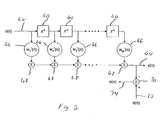
A transversal filter (or tapped delay line) is the most
common filter structure. A tapped delay line comprising a series
of delay elements 60 is illustrated in Figure 2. The input to
the filter is the signal u(n) 62. The output of each tap is
weighted by a tap weight element 66 defined by a tap vector w1,
w2, etc. A series of adders 68 sum these products to produce the
filter output y(n) 64.
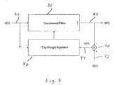
In an adaptive transversal filter, each tap vector w is
adjusted according to some adaptation criterion or cost function.
Figure 3 illustrates a tap weight adapter 82 that updates the tap
weights for a transversal filter 80 according to an error signal
e(n) 74.
Using the notation and perspective of Haykin, the equation
for this error at time
i is
ei = di - wH iui
where
The superscript H indicates a Hermitian transpose, which is
equivalent to a standard transpose for real data.
The filter output is
yi = wH iui
The single channel filtering input vector is defined by
ui = ui ,ui -1,...,ui - L -1 T
where
In other words, this ui is a tapped-delay line and w T / i
contains the weighting values of each tap.
In the Least Squares (LS) adaption criterion, the goal is
to minimize the power of the error signal, as given by
which corresponds to minimizing the sample variance given by
In the Least-Mean-Square (LMS) technique the LS criterion
is implemented by adjusting the tap vector wi by the multiple of
the product of the error ei and the input vector ui .
ei = di - wT iui
wi +1 = wi + µuiei
This is a stochastic gradient algorithm, because each step
may not proceed down the gradient. In other words, convergence
only will occur in the average, assuming certain stability
conditions are satisfied.
The Zero-Forcing Least-Mean-Square (ZFLMS), also known as
the Sign-Sign (SS) algorithm is like LMS, but the multiply is
performed only upon the sign bits,
wi +1 = wi + µsign(ui )sign(ei ).
This is more suitable for real-time applications, because
it avoids the multiplications. Under certain conditions, ZFLMS
can be proven to converge to the same point as LMS. See
Bodenschatz, J. and Nikias, C.L., "Symmetric alpha-stable filter
theory," IEEE Transactions on Signal Processing, vol. 45, no. 9,
pp. 2301-06, 1997.
There are many other methods to adapt the filter taps, such
as algorithms based upon recursive least squares.
The most common method of channel equalization uses an
adaptive equalizer to undo the effects of the channel. While this
generally does not remove all of the channel effects, it is still
a very powerful technique. If the transmitted signal is known,
a value of di for Equation 6 will be known. An example of this is
the use in voice-grade modems of a known training sequence for
initialization. If the desired signal, di , is not known, but the
signal being equalized is a bauded signal with a finite
constellation of transmitted values, "decision-directed
equalization" or "blind equalization" may be used.
In decision-directed equalization, the desired signal, di ,
is chosen as the closest point on the transmitted constellation.
This gives us an error, ei , from Equation 6 to use in the tap
update equations, such as Equations 7 or 8.
There are many types of blind equalization techniques. These
techniques rely on statistics to calculate a value of ei for use
in the tap update equations, such as Equations 7 or 8.
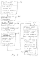
Figure 4 illustrates one embodiment of a decision directed
equalizer in accordance with the invention. The operation of
this embodiment will be discussed in conjunction with the
flowchart of Figure 5.
Briefly, as described in Figure 4 the equalizer includes a
transversal filter 86 that operates in conjunction with a
threshold compare and update circuit 92 and a tap weight updater
100 to process an input signal u(n) 88 to produce an output
signal y(n) 90. Referring to Figure 5, initially, as described
at block 102, the weight of each tap is set. As discussed above,
the largest tap is set to unity and the taps other than the unity
tap will be constrained to have a magnitude less than unity.
While the other taps typically are initialized to zero; they
could be set to some other value to facilitate convergence.
As described at block 104, the thresholds are set to an
initial value. For constellations other than BPSK, the value of
the threshold should be initialized to a value that is reasonable
close to the scaled value expected for the various points in the
constellation. Typically this is a relative simple operation,
although it may require an additional initialization algorithm.
In one embodiment the initialization algorithm is based on the
incoming signal strength.
As the transversal filter 86 processes the input signal u(n)
88 (block 106) it generates an output y(n) 90 that is routed to
the threshold compare and update circuit 92 (block 108). As
represented by block 110, the threshold compare and update
circuit 92 compares y(n) 90 with one or more thresholds to select
a desired response d(n) 94. This operation is discussed in more
detail below in conjunction with specific decision directed
applications. An adder 96 subtracts y(n) 90 from d(n) 94 to
produce an error signal e(n) 98 (block 112). Next, the tap
weight updater 100 updates the tap weights based, in part, on
e(n) 98 and u(n) 88 (block 114). Again, the tap weights are
constrained to unity and less than unity as discussed above.
Then, at block 116, the threshold compare and update circuit 92
updates the thresholds based on comparison of y(n) 90 with the
thresholds. The process then repeats to process each sample of
the input signal, continually updating the tap weights and the
thresholds to adapt to, for example, the transmission channel.
The adaptation to calculate the threshold may be better
understood by illustrating the operation with a specific example.
The following example involves a three level signal such as MLT3.
The transmitted signal can be viewed as being { -1, 0, 1 }. After
equalization, all outputs should fall around scaled version of
those three levels, { -2T, 0, 2T }. For decision-directed
equalization, the signal may be deemed high if it is above
T, and
deemed low if it is below -
T, or more formally:
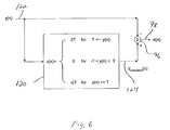
Such a comparison operation is used in the threshold
comparator 120 of Figure 6. As described in Figure 6, the
threshold comparator 120 compares the input y(n) 122 with the
threshold to generate a desired (e.g., estimated) signal d(n)
124.
Statistically, the high signals should be symmetrically
clustered around
2T, and the low signals should be clustered
around
-2T. Therefore, the threshold compare and update procedure
can use the following algorithm to update the threshold:
Ti +1 = Ti + ΔTi ,
where µ is a small constant.
Adaptation can also be performed by using a scaled version
of the difference:
This is potentially faster, but values of |y| just above T,
which are likely to be in error, will have a greater impact on
T than values near T. Thus, the method in Equation 10 typically
is more robust.
Adaptive thresholding also is also applicable to Binary
Phase-Shift Keying signals. In this case, the decision threshold
is constant at zero. However, a value of
di is needed for
Equation 6. This value can be set according to the following
equation:
Then
Ti may be adapted using Equation 11 and:
In this example, a factor of 2 was used to multiply T in
Equation 14 to remain consistent with Equation 9, but this is not
necessary here, since this is the only use of T, except for its
update.
In another embodiment, adaptive thresholding may be used in
conjunction with modems that use constellations that may have as
many as 256 (or more) points. Here, the decision thresholds and
ideal decision values are calculated as multiples of T. However,
depending upon the specific implementation, these multiplications
may be more burdensome than the multiply in the tapped delay line
that is being replaced. Thus, adaptive thresholding may, or may
not, be advantageous for all implementations.
In another embodiment, adaptive thresholding may be used in
conjunction with a decision-feedback equalizer (DFE) that is
combined with the transversal filter. The output of the DFE is
added to the output yi of the transversal filter before ei is
calculated. The resulting ei is used to update both filters. To
use adaptive filtering with a DFE, the DFE is added as it would
be with a conventional transversal filter. All of the taps of
the DFE may remain adaptive.
In another embodiment, adaptive thresholding may be used
with algorithms that use a known training sequence. In this
case, instead of using the decisions calculations, such as
Equations 9 or 14, di may be calculated by multiplying by the
appropriate factor of T.
Blind equalization cost functions contain constants that are
calculated from the statistics of the data, such as E{|y|2}. To
extend the adaptive threshold method to embodiments that use
blind equalization, the constants can be re-estimated to track
the output. However, a potentially more effective approach
involves the use of step-wise adjustments, so that the constants
have the correct ratio of output points above and below them.
For example, using a Sato algorithm, the error signal, ei , is the
vector from yi to a circle of the appropriate radius. Using the
adaptive thresholding algorithm, the radius is adaptively
updated, instead of changing the largest tap of the equalizer.
As with BPSK, this adaptive quantity is not used as a decision
threshold per se, but the manner in which ei is calculated is
adapted.
In general, adaptive thresholding may be combined with any
adaptation algorithm that does not have infinite memory. The
unity tap is unchanged in the adaptation, and the other taps are
adjusted to minimize ei of Equation 1. Any stochastic gradient
algorithm is suitable. Stochastic Newton algorithms can be used,
but the memory must be finite. For example, this can be
accomplished in RLS by having the λ < 1, or by using a window of
finite length. In effect, the finite memory allows the filter
to "forget" the errors ei that were calculated before the
threshold algorithm converged.
Thus the teaching of the invention can effectively be
applied to wide classes of channel equalization including, for
example, T100/T1000, QAM, DVI, and magnetic media. Figure 7
illustrates a generalized depiction of a data communication
system S consisting of a transmitter 130 that sends a signal over
a channel 132 to a receiver 134. Typically the receiver includes
a channel interface 136 that is adapted to receive signals from
a particular channel (e.g., T100/T1000). The received signals
are then processed by an adaptive equalizer 138 in accordance
with the teachings herein.
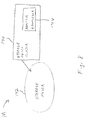
Figure 8 illustrates a generalized depiction of a storage
media system M where a storage media reader 140 reads a storage
media 142. The storage media reader 140 generates signals that
are processed by an adaptive equalizer 144 which, for example,
equalizes the signal to remove undesirable signal artifacts
introduced by the media 142. For example, the storage media 142
may be a magnetic media or a compact disk media. As discussed
above the adaptive equalizer of Figures 7 and 8 may incorporate
a variety of adaptive equalization techniques in implementing the
teachings of the invention.
Adaptive thresholding provides a number of advantages over
some conventional equalization techniques. A multiply may be removed;
the dynamic range per number of bits in the system may be
increased; and the structure may allow the ratio of the
largest/unity tap to the threshold to be computed with greater
accuracy, thereby increasing performance.
Replacing the multiply with the thresholding mechanism saves
computation, especially since the multiply being replaced
typically would need the highest precision of any multiply in the
equalizer. In hardware implementations, this is very important
for saving silicon area and minimizing path delays, thereby
permitting the integrated circuit to be clocked at a higher rate.
In real-time DSP software, it reduces computations and increases
speed. For non-real time software on a general-purpose computer,
it will increase execution speed.
The unity tap constrains the range signal going through the
equalizer, reducing the number of bits needed to accurately
represent the computed values. The number of bits also is reduced
in the DFE, if it is present. In hardware implementations, this
reduces gate count; in software, it may permit faster execution.
In both cases, it facilitates system design and testing.
In conventional filters, the value of the largest tap may
be adjusted relative to a fixed value. Since the largest tap is
an input to a multiply, there is a severe practical limit to how
many bits can be used to represent it. In the techniques
described herein, the largest tap may be held at unity and the
value of the threshold adjusted. As the threshold is an input
to a compare, it can more practically be represented by many more
bits. With precision, the ratio of the largest tap to the
threshold has the same theoretical final value. However, the
difference in bits allows the ratio to be more accurate with
adaptive thresholding. This greater accuracy will result in
improved accuracy of filter shape and the filter output.
Typically, a system constructed according to invention will
be implemented in an integrated circuit and/or as software code
that is executed by a processing device. For example, an
equalizer incorporating these techniques may be hardcoded into
a data communications transceiver on an integrated circuit and/or
a circuit board. In addition, these techniques may be
implemented in software that is loaded, for example, into a
digital signal processor, a conventional central processing unit
or a custom integrated circuit.
In summary, the invention described herein teaches improved
techniques for providing adaptive equalization. While certain
exemplary embodiments have been described in detail and shown in
the accompanying drawings, it is to be understood that such
embodiments are merely illustrative of and not restrictive of the
broad invention. It will thus be recognized that various
modifications may be made to the illustrated and other
embodiments of the invention described above, without departing
from the broad inventive scope thereof. In view of the above it
will be understood that the invention is not limited to the
particular embodiments or arrangements disclosed, but is rather
intended to cover any changes, adaptations or modifications which
are within the scope and spirit of the invention as defined by
the appended claims.