EP1326238A2 - Flexible magnetic recording medium - Google Patents
Flexible magnetic recording medium Download PDFInfo
- Publication number
- EP1326238A2 EP1326238A2 EP02028010A EP02028010A EP1326238A2 EP 1326238 A2 EP1326238 A2 EP 1326238A2 EP 02028010 A EP02028010 A EP 02028010A EP 02028010 A EP02028010 A EP 02028010A EP 1326238 A2 EP1326238 A2 EP 1326238A2
- Authority
- EP
- European Patent Office
- Prior art keywords
- magnetic
- recording medium
- magnetic layer
- magnetic recording
- layer
- Prior art date
- Legal status (The legal status is an assumption and is not a legal conclusion. Google has not performed a legal analysis and makes no representation as to the accuracy of the status listed.)
- Withdrawn
Links
- 230000005291 magnetic effect Effects 0.000 title claims abstract description 778
- 239000002245 particle Substances 0.000 claims abstract description 97
- 239000000843 powder Substances 0.000 claims abstract description 79
- 230000005294 ferromagnetic effect Effects 0.000 claims abstract description 75
- 239000010432 diamond Substances 0.000 claims abstract description 73
- 239000000758 substrate Substances 0.000 claims abstract description 67
- 229910003460 diamond Inorganic materials 0.000 claims abstract description 59
- 238000000576 coating method Methods 0.000 claims description 216
- 239000011248 coating agent Substances 0.000 claims description 211
- 229920005749 polyurethane resin Polymers 0.000 claims description 90
- 238000012546 transfer Methods 0.000 claims description 74
- 239000000314 lubricant Substances 0.000 claims description 65
- 239000006247 magnetic powder Substances 0.000 claims description 45
- 229920005989 resin Polymers 0.000 claims description 43
- 239000011347 resin Substances 0.000 claims description 43
- 238000004519 manufacturing process Methods 0.000 claims description 16
- 229910052783 alkali metal Inorganic materials 0.000 claims description 14
- 239000007788 liquid Substances 0.000 claims description 11
- 125000004435 hydrogen atom Chemical group [H]* 0.000 claims description 9
- 150000001340 alkali metals Chemical class 0.000 claims description 7
- 125000003178 carboxy group Chemical group [H]OC(*)=O 0.000 claims description 7
- 150000003863 ammonium salts Chemical class 0.000 claims description 5
- 238000009937 brining Methods 0.000 claims 1
- LGEZTMRIZWCDLW-UHFFFAOYSA-N 14-methylpentadecyl octadecanoate Chemical compound CCCCCCCCCCCCCCCCCC(=O)OCCCCCCCCCCCCCC(C)C LGEZTMRIZWCDLW-UHFFFAOYSA-N 0.000 description 64
- 229940078545 isocetyl stearate Drugs 0.000 description 64
- 238000000034 method Methods 0.000 description 55
- -1 acrylic ester Chemical class 0.000 description 53
- ZWEHNKRNPOVVGH-UHFFFAOYSA-N 2-Butanone Chemical compound CCC(C)=O ZWEHNKRNPOVVGH-UHFFFAOYSA-N 0.000 description 48
- 239000011230 binding agent Substances 0.000 description 46
- 239000006229 carbon black Substances 0.000 description 45
- OKTJSMMVPCPJKN-UHFFFAOYSA-N Carbon Chemical compound [C] OKTJSMMVPCPJKN-UHFFFAOYSA-N 0.000 description 37
- 229910052799 carbon Inorganic materials 0.000 description 35
- VYPSYNLAJGMNEJ-UHFFFAOYSA-N Silicium dioxide Chemical compound O=[Si]=O VYPSYNLAJGMNEJ-UHFFFAOYSA-N 0.000 description 30
- 239000000654 additive Substances 0.000 description 28
- PNEYBMLMFCGWSK-UHFFFAOYSA-N aluminium oxide Inorganic materials [O-2].[O-2].[O-2].[Al+3].[Al+3] PNEYBMLMFCGWSK-UHFFFAOYSA-N 0.000 description 26
- 229920001228 polyisocyanate Polymers 0.000 description 25
- 239000005056 polyisocyanate Substances 0.000 description 25
- 238000001035 drying Methods 0.000 description 24
- XEEYBQQBJWHFJM-UHFFFAOYSA-N Iron Chemical compound [Fe] XEEYBQQBJWHFJM-UHFFFAOYSA-N 0.000 description 22
- GWEVSGVZZGPLCZ-UHFFFAOYSA-N Titan oxide Chemical compound O=[Ti]=O GWEVSGVZZGPLCZ-UHFFFAOYSA-N 0.000 description 22
- 229910052751 metal Inorganic materials 0.000 description 22
- 239000002184 metal Substances 0.000 description 22
- 239000006185 dispersion Substances 0.000 description 21
- 229910000859 α-Fe Inorganic materials 0.000 description 21
- XDTMQSROBMDMFD-UHFFFAOYSA-N Cyclohexane Chemical compound C1CCCCC1 XDTMQSROBMDMFD-UHFFFAOYSA-N 0.000 description 20
- 239000002253 acid Substances 0.000 description 20
- 238000010276 construction Methods 0.000 description 20
- 235000014113 dietary fatty acids Nutrition 0.000 description 20
- 230000000694 effects Effects 0.000 description 20
- 239000000194 fatty acid Substances 0.000 description 20
- 229930195729 fatty acid Natural products 0.000 description 20
- 239000000463 material Substances 0.000 description 20
- 239000003082 abrasive agent Substances 0.000 description 19
- 239000000126 substance Substances 0.000 description 18
- ZQPPMHVWECSIRJ-UHFFFAOYSA-N Oleic acid Natural products CCCCCCCCC=CCCCCCCCC(O)=O ZQPPMHVWECSIRJ-UHFFFAOYSA-N 0.000 description 17
- ZQPPMHVWECSIRJ-MDZDMXLPSA-N elaidic acid Chemical compound CCCCCCCC\C=C\CCCCCCCC(O)=O ZQPPMHVWECSIRJ-MDZDMXLPSA-N 0.000 description 17
- QXJSBBXBKPUZAA-UHFFFAOYSA-N isooleic acid Natural products CCCCCCCC=CCCCCCCCCC(O)=O QXJSBBXBKPUZAA-UHFFFAOYSA-N 0.000 description 17
- QIQXTHQIDYTFRH-UHFFFAOYSA-N octadecanoic acid Chemical compound CCCCCCCCCCCCCCCCCC(O)=O QIQXTHQIDYTFRH-UHFFFAOYSA-N 0.000 description 17
- 239000002904 solvent Substances 0.000 description 17
- WRIDQFICGBMAFQ-UHFFFAOYSA-N (E)-8-Octadecenoic acid Natural products CCCCCCCCCC=CCCCCCCC(O)=O WRIDQFICGBMAFQ-UHFFFAOYSA-N 0.000 description 16
- LQJBNNIYVWPHFW-UHFFFAOYSA-N 20:1omega9c fatty acid Natural products CCCCCCCCCCC=CCCCCCCCC(O)=O LQJBNNIYVWPHFW-UHFFFAOYSA-N 0.000 description 16
- QSBYPNXLFMSGKH-UHFFFAOYSA-N 9-Heptadecensaeure Natural products CCCCCCCC=CCCCCCCCC(O)=O QSBYPNXLFMSGKH-UHFFFAOYSA-N 0.000 description 16
- 239000005642 Oleic acid Substances 0.000 description 16
- 235000021355 Stearic acid Nutrition 0.000 description 16
- 229920001577 copolymer Polymers 0.000 description 16
- OQCDKBAXFALNLD-UHFFFAOYSA-N octadecanoic acid Natural products CCCCCCCC(C)CCCCCCCCC(O)=O OQCDKBAXFALNLD-UHFFFAOYSA-N 0.000 description 16
- 239000008117 stearic acid Substances 0.000 description 16
- 150000001875 compounds Chemical class 0.000 description 15
- 229910052593 corundum Inorganic materials 0.000 description 15
- 239000000203 mixture Substances 0.000 description 14
- 229920005862 polyol Polymers 0.000 description 14
- 125000000217 alkyl group Chemical group 0.000 description 13
- 238000009826 distribution Methods 0.000 description 13
- 239000004615 ingredient Substances 0.000 description 13
- 230000007774 longterm Effects 0.000 description 13
- 230000002829 reductive effect Effects 0.000 description 13
- 238000011282 treatment Methods 0.000 description 13
- LFQSCWFLJHTTHZ-UHFFFAOYSA-N Ethanol Chemical compound CCO LFQSCWFLJHTTHZ-UHFFFAOYSA-N 0.000 description 12
- QLZHNIAADXEJJP-UHFFFAOYSA-N Phenylphosphonic acid Chemical compound OP(O)(=O)C1=CC=CC=C1 QLZHNIAADXEJJP-UHFFFAOYSA-N 0.000 description 12
- 150000002009 diols Chemical class 0.000 description 12
- 238000004898 kneading Methods 0.000 description 12
- 229910052710 silicon Inorganic materials 0.000 description 12
- 229920005906 polyester polyol Polymers 0.000 description 11
- 150000003077 polyols Chemical class 0.000 description 11
- 239000000377 silicon dioxide Substances 0.000 description 11
- 229930185605 Bisphenol Natural products 0.000 description 10
- 238000003490 calendering Methods 0.000 description 10
- 229910001845 yogo sapphire Inorganic materials 0.000 description 10
- 238000006243 chemical reaction Methods 0.000 description 9
- 239000013078 crystal Substances 0.000 description 9
- PUPZLCDOIYMWBV-UHFFFAOYSA-N (+/-)-1,3-Butanediol Chemical compound CC(O)CCO PUPZLCDOIYMWBV-UHFFFAOYSA-N 0.000 description 8
- 239000004970 Chain extender Substances 0.000 description 8
- XUIMIQQOPSSXEZ-UHFFFAOYSA-N Silicon Chemical compound [Si] XUIMIQQOPSSXEZ-UHFFFAOYSA-N 0.000 description 8
- 230000015572 biosynthetic process Effects 0.000 description 8
- 229910052681 coesite Inorganic materials 0.000 description 8
- 229910052906 cristobalite Inorganic materials 0.000 description 8
- 238000010438 heat treatment Methods 0.000 description 8
- 238000002156 mixing Methods 0.000 description 8
- 239000003921 oil Substances 0.000 description 8
- AJCDFVKYMIUXCR-UHFFFAOYSA-N oxobarium;oxo(oxoferriooxy)iron Chemical compound [Ba]=O.O=[Fe]O[Fe]=O.O=[Fe]O[Fe]=O.O=[Fe]O[Fe]=O.O=[Fe]O[Fe]=O.O=[Fe]O[Fe]=O.O=[Fe]O[Fe]=O AJCDFVKYMIUXCR-UHFFFAOYSA-N 0.000 description 8
- 239000004576 sand Substances 0.000 description 8
- 239000010703 silicon Substances 0.000 description 8
- 229910052682 stishovite Inorganic materials 0.000 description 8
- 229910052905 tridymite Inorganic materials 0.000 description 8
- 150000002148 esters Chemical class 0.000 description 7
- 230000005415 magnetization Effects 0.000 description 7
- 229920002635 polyurethane Polymers 0.000 description 7
- 239000004814 polyurethane Substances 0.000 description 7
- 238000013441 quality evaluation Methods 0.000 description 7
- WSFSSNUMVMOOMR-UHFFFAOYSA-N Formaldehyde Chemical compound O=C WSFSSNUMVMOOMR-UHFFFAOYSA-N 0.000 description 6
- BZHJMEDXRYGGRV-UHFFFAOYSA-N Vinyl chloride Chemical compound ClC=C BZHJMEDXRYGGRV-UHFFFAOYSA-N 0.000 description 6
- WNLRTRBMVRJNCN-UHFFFAOYSA-N adipic acid Chemical compound OC(=O)CCCCC(O)=O WNLRTRBMVRJNCN-UHFFFAOYSA-N 0.000 description 6
- 239000000969 carrier Substances 0.000 description 6
- 229920001971 elastomer Polymers 0.000 description 6
- 150000004665 fatty acids Chemical class 0.000 description 6
- 230000001965 increasing effect Effects 0.000 description 6
- 239000003960 organic solvent Substances 0.000 description 6
- 229920003023 plastic Polymers 0.000 description 6
- 239000004033 plastic Substances 0.000 description 6
- 230000008569 process Effects 0.000 description 6
- 239000005060 rubber Substances 0.000 description 6
- 238000005245 sintering Methods 0.000 description 6
- 239000004952 Polyamide Substances 0.000 description 5
- 239000004642 Polyimide Substances 0.000 description 5
- 150000001298 alcohols Chemical class 0.000 description 5
- 125000002947 alkylene group Chemical group 0.000 description 5
- 239000002216 antistatic agent Substances 0.000 description 5
- 125000004429 atom Chemical group 0.000 description 5
- IISBACLAFKSPIT-UHFFFAOYSA-N bisphenol A Chemical compound C=1C=C(O)C=CC=1C(C)(C)C1=CC=C(O)C=C1 IISBACLAFKSPIT-UHFFFAOYSA-N 0.000 description 5
- 239000010431 corundum Substances 0.000 description 5
- 125000005442 diisocyanate group Chemical group 0.000 description 5
- 229920002647 polyamide Polymers 0.000 description 5
- 229920000139 polyethylene terephthalate Polymers 0.000 description 5
- 239000005020 polyethylene terephthalate Substances 0.000 description 5
- 229920001721 polyimide Polymers 0.000 description 5
- 230000003449 preventive effect Effects 0.000 description 5
- 230000009467 reduction Effects 0.000 description 5
- 230000003068 static effect Effects 0.000 description 5
- 150000005846 sugar alcohols Polymers 0.000 description 5
- 238000004381 surface treatment Methods 0.000 description 5
- 239000012756 surface treatment agent Substances 0.000 description 5
- 239000011701 zinc Substances 0.000 description 5
- IJGRMHOSHXDMSA-UHFFFAOYSA-N Atomic nitrogen Chemical compound N#N IJGRMHOSHXDMSA-UHFFFAOYSA-N 0.000 description 4
- KAKZBPTYRLMSJV-UHFFFAOYSA-N Butadiene Chemical compound C=CC=C KAKZBPTYRLMSJV-UHFFFAOYSA-N 0.000 description 4
- CYRRYHPFWXNRRH-UHFFFAOYSA-N C(CCCCCCCCCCCCCCCCC)(=O)OOCCCC Chemical compound C(CCCCCCCCCCCCCCCCC)(=O)OOCCCC CYRRYHPFWXNRRH-UHFFFAOYSA-N 0.000 description 4
- 239000004593 Epoxy Substances 0.000 description 4
- IAYPIBMASNFSPL-UHFFFAOYSA-N Ethylene oxide Chemical compound C1CO1 IAYPIBMASNFSPL-UHFFFAOYSA-N 0.000 description 4
- PEDCQBHIVMGVHV-UHFFFAOYSA-N Glycerine Chemical compound OCC(O)CO PEDCQBHIVMGVHV-UHFFFAOYSA-N 0.000 description 4
- LRHPLDYGYMQRHN-UHFFFAOYSA-N N-Butanol Chemical compound CCCCO LRHPLDYGYMQRHN-UHFFFAOYSA-N 0.000 description 4
- PPBRXRYQALVLMV-UHFFFAOYSA-N Styrene Chemical compound C=CC1=CC=CC=C1 PPBRXRYQALVLMV-UHFFFAOYSA-N 0.000 description 4
- 238000010521 absorption reaction Methods 0.000 description 4
- 230000000996 additive effect Effects 0.000 description 4
- 125000001931 aliphatic group Chemical group 0.000 description 4
- JZQOJFLIJNRDHK-CMDGGOBGSA-N alpha-irone Chemical compound CC1CC=C(C)C(\C=C\C(C)=O)C1(C)C JZQOJFLIJNRDHK-CMDGGOBGSA-N 0.000 description 4
- 229910052782 aluminium Inorganic materials 0.000 description 4
- QVGXLLKOCUKJST-UHFFFAOYSA-N atomic oxygen Chemical compound [O] QVGXLLKOCUKJST-UHFFFAOYSA-N 0.000 description 4
- 229910052796 boron Inorganic materials 0.000 description 4
- 230000008859 change Effects 0.000 description 4
- 238000006757 chemical reactions by type Methods 0.000 description 4
- 238000001816 cooling Methods 0.000 description 4
- 238000005260 corrosion Methods 0.000 description 4
- 230000007797 corrosion Effects 0.000 description 4
- 238000010586 diagram Methods 0.000 description 4
- MTHSVFCYNBDYFN-UHFFFAOYSA-N diethylene glycol Chemical compound OCCOCCO MTHSVFCYNBDYFN-UHFFFAOYSA-N 0.000 description 4
- 238000011156 evaluation Methods 0.000 description 4
- 230000009477 glass transition Effects 0.000 description 4
- 238000009499 grossing Methods 0.000 description 4
- 239000012535 impurity Substances 0.000 description 4
- 239000012948 isocyanate Substances 0.000 description 4
- 150000002513 isocyanates Chemical class 0.000 description 4
- 238000005457 optimization Methods 0.000 description 4
- 229910052760 oxygen Inorganic materials 0.000 description 4
- 239000001301 oxygen Substances 0.000 description 4
- 238000005498 polishing Methods 0.000 description 4
- 238000002360 preparation method Methods 0.000 description 4
- 230000002265 prevention Effects 0.000 description 4
- HBMJWWWQQXIZIP-UHFFFAOYSA-N silicon carbide Chemical compound [Si+]#[C-] HBMJWWWQQXIZIP-UHFFFAOYSA-N 0.000 description 4
- 229910010271 silicon carbide Inorganic materials 0.000 description 4
- 238000004544 sputter deposition Methods 0.000 description 4
- 239000004575 stone Substances 0.000 description 4
- 238000001308 synthesis method Methods 0.000 description 4
- 229920005992 thermoplastic resin Polymers 0.000 description 4
- 229920001187 thermosetting polymer Polymers 0.000 description 4
- 229920002554 vinyl polymer Polymers 0.000 description 4
- NIXOWILDQLNWCW-UHFFFAOYSA-N 2-Propenoic acid Natural products OC(=O)C=C NIXOWILDQLNWCW-UHFFFAOYSA-N 0.000 description 3
- NHUXFMNHQIITCP-UHFFFAOYSA-N 2-butoxyethyl octadecanoate Chemical compound CCCCCCCCCCCCCCCCCC(=O)OCCOCCCC NHUXFMNHQIITCP-UHFFFAOYSA-N 0.000 description 3
- VPWNQTHUCYMVMZ-UHFFFAOYSA-N 4,4'-sulfonyldiphenol Chemical compound C1=CC(O)=CC=C1S(=O)(=O)C1=CC=C(O)C=C1 VPWNQTHUCYMVMZ-UHFFFAOYSA-N 0.000 description 3
- QTBSBXVTEAMEQO-UHFFFAOYSA-N Acetic acid Chemical compound CC(O)=O QTBSBXVTEAMEQO-UHFFFAOYSA-N 0.000 description 3
- CSCPPACGZOOCGX-UHFFFAOYSA-N Acetone Chemical compound CC(C)=O CSCPPACGZOOCGX-UHFFFAOYSA-N 0.000 description 3
- 229910052582 BN Inorganic materials 0.000 description 3
- GIXXQTYGFOHYPT-UHFFFAOYSA-N Bisphenol P Chemical compound C=1C=C(C(C)(C)C=2C=CC(O)=CC=2)C=CC=1C(C)(C)C1=CC=C(O)C=C1 GIXXQTYGFOHYPT-UHFFFAOYSA-N 0.000 description 3
- PZNSFCLAULLKQX-UHFFFAOYSA-N Boron nitride Chemical compound N#B PZNSFCLAULLKQX-UHFFFAOYSA-N 0.000 description 3
- YMWUJEATGCHHMB-UHFFFAOYSA-N Dichloromethane Chemical compound ClCCl YMWUJEATGCHHMB-UHFFFAOYSA-N 0.000 description 3
- LYCAIKOWRPUZTN-UHFFFAOYSA-N Ethylene glycol Chemical compound OCCO LYCAIKOWRPUZTN-UHFFFAOYSA-N 0.000 description 3
- KFZMGEQAYNKOFK-UHFFFAOYSA-N Isopropanol Chemical compound CC(C)O KFZMGEQAYNKOFK-UHFFFAOYSA-N 0.000 description 3
- OKKJLVBELUTLKV-UHFFFAOYSA-N Methanol Chemical compound OC OKKJLVBELUTLKV-UHFFFAOYSA-N 0.000 description 3
- 229910052779 Neodymium Inorganic materials 0.000 description 3
- OFOBLEOULBTSOW-UHFFFAOYSA-N Propanedioic acid Natural products OC(=O)CC(O)=O OFOBLEOULBTSOW-UHFFFAOYSA-N 0.000 description 3
- GOOHAUXETOMSMM-UHFFFAOYSA-N Propylene oxide Chemical compound CC1CO1 GOOHAUXETOMSMM-UHFFFAOYSA-N 0.000 description 3
- 229910052581 Si3N4 Inorganic materials 0.000 description 3
- YXFVVABEGXRONW-UHFFFAOYSA-N Toluene Chemical compound CC1=CC=CC=C1 YXFVVABEGXRONW-UHFFFAOYSA-N 0.000 description 3
- WGLPBDUCMAPZCE-UHFFFAOYSA-N Trioxochromium Chemical compound O=[Cr](=O)=O WGLPBDUCMAPZCE-UHFFFAOYSA-N 0.000 description 3
- ORLQHILJRHBSAY-UHFFFAOYSA-N [1-(hydroxymethyl)cyclohexyl]methanol Chemical compound OCC1(CO)CCCCC1 ORLQHILJRHBSAY-UHFFFAOYSA-N 0.000 description 3
- 239000001361 adipic acid Substances 0.000 description 3
- 235000011037 adipic acid Nutrition 0.000 description 3
- 229910000423 chromium oxide Inorganic materials 0.000 description 3
- 229910052802 copper Inorganic materials 0.000 description 3
- PDXRQENMIVHKPI-UHFFFAOYSA-N cyclohexane-1,1-diol Chemical compound OC1(O)CCCCC1 PDXRQENMIVHKPI-UHFFFAOYSA-N 0.000 description 3
- 230000007547 defect Effects 0.000 description 3
- 229910052746 lanthanum Inorganic materials 0.000 description 3
- 229910052759 nickel Inorganic materials 0.000 description 3
- 229910052698 phosphorus Inorganic materials 0.000 description 3
- 229920000642 polymer Polymers 0.000 description 3
- 229920001451 polypropylene glycol Polymers 0.000 description 3
- 239000011164 primary particle Substances 0.000 description 3
- 235000012239 silicon dioxide Nutrition 0.000 description 3
- HQVNEWCFYHHQES-UHFFFAOYSA-N silicon nitride Chemical compound N12[Si]34N5[Si]62N3[Si]51N64 HQVNEWCFYHHQES-UHFFFAOYSA-N 0.000 description 3
- 229910052712 strontium Inorganic materials 0.000 description 3
- CIOAGBVUUVVLOB-UHFFFAOYSA-N strontium atom Chemical compound [Sr] CIOAGBVUUVVLOB-UHFFFAOYSA-N 0.000 description 3
- OGIDPMRJRNCKJF-UHFFFAOYSA-N titanium oxide Inorganic materials [Ti]=O OGIDPMRJRNCKJF-UHFFFAOYSA-N 0.000 description 3
- MTPVUVINMAGMJL-UHFFFAOYSA-N trimethyl(1,1,2,2,2-pentafluoroethyl)silane Chemical compound C[Si](C)(C)C(F)(F)C(F)(F)F MTPVUVINMAGMJL-UHFFFAOYSA-N 0.000 description 3
- 229910052727 yttrium Inorganic materials 0.000 description 3
- 229910052725 zinc Inorganic materials 0.000 description 3
- CRPRCSYCZWFVED-UHFFFAOYSA-N (4-ethylphenyl)phosphonic acid Chemical compound CCC1=CC=C(P(O)(O)=O)C=C1 CRPRCSYCZWFVED-UHFFFAOYSA-N 0.000 description 2
- QMMJWQMCMRUYTG-UHFFFAOYSA-N 1,2,4,5-tetrachloro-3-(trifluoromethyl)benzene Chemical compound FC(F)(F)C1=C(Cl)C(Cl)=CC(Cl)=C1Cl QMMJWQMCMRUYTG-UHFFFAOYSA-N 0.000 description 2
- RYHBNJHYFVUHQT-UHFFFAOYSA-N 1,4-Dioxane Chemical compound C1COCCO1 RYHBNJHYFVUHQT-UHFFFAOYSA-N 0.000 description 2
- CUVLMZNMSPJDON-UHFFFAOYSA-N 1-(1-butoxypropan-2-yloxy)propan-2-ol Chemical compound CCCCOCC(C)OCC(C)O CUVLMZNMSPJDON-UHFFFAOYSA-N 0.000 description 2
- OEPOKWHJYJXUGD-UHFFFAOYSA-N 2-(3-phenylmethoxyphenyl)-1,3-thiazole-4-carbaldehyde Chemical compound O=CC1=CSC(C=2C=C(OCC=3C=CC=CC=3)C=CC=2)=N1 OEPOKWHJYJXUGD-UHFFFAOYSA-N 0.000 description 2
- CBECDWUDYQOTSW-UHFFFAOYSA-N 2-ethylbut-3-enal Chemical compound CCC(C=C)C=O CBECDWUDYQOTSW-UHFFFAOYSA-N 0.000 description 2
- QPRQEDXDYOZYLA-UHFFFAOYSA-N 2-methylbutan-1-ol Chemical compound CCC(C)CO QPRQEDXDYOZYLA-UHFFFAOYSA-N 0.000 description 2
- UPMLOUAZCHDJJD-UHFFFAOYSA-N 4,4'-Diphenylmethane Diisocyanate Chemical compound C1=CC(N=C=O)=CC=C1CC1=CC=C(N=C=O)C=C1 UPMLOUAZCHDJJD-UHFFFAOYSA-N 0.000 description 2
- NLHHRLWOUZZQLW-UHFFFAOYSA-N Acrylonitrile Chemical compound C=CC#N NLHHRLWOUZZQLW-UHFFFAOYSA-N 0.000 description 2
- QGZKDVFQNNGYKY-UHFFFAOYSA-O Ammonium Chemical compound [NH4+] QGZKDVFQNNGYKY-UHFFFAOYSA-O 0.000 description 2
- UHOVQNZJYSORNB-UHFFFAOYSA-N Benzene Chemical compound C1=CC=CC=C1 UHOVQNZJYSORNB-UHFFFAOYSA-N 0.000 description 2
- 229910052684 Cerium Inorganic materials 0.000 description 2
- HEDRZPFGACZZDS-UHFFFAOYSA-N Chloroform Chemical compound ClC(Cl)Cl HEDRZPFGACZZDS-UHFFFAOYSA-N 0.000 description 2
- ASMQGLCHMVWBQR-UHFFFAOYSA-N Diphenyl phosphate Chemical compound C=1C=CC=CC=1OP(=O)(O)OC1=CC=CC=C1 ASMQGLCHMVWBQR-UHFFFAOYSA-N 0.000 description 2
- VGGSQFUCUMXWEO-UHFFFAOYSA-N Ethene Chemical compound C=C VGGSQFUCUMXWEO-UHFFFAOYSA-N 0.000 description 2
- 239000005977 Ethylene Substances 0.000 description 2
- 239000005057 Hexamethylene diisocyanate Substances 0.000 description 2
- QIGBRXMKCJKVMJ-UHFFFAOYSA-N Hydroquinone Chemical compound OC1=CC=C(O)C=C1 QIGBRXMKCJKVMJ-UHFFFAOYSA-N 0.000 description 2
- UQSXHKLRYXJYBZ-UHFFFAOYSA-N Iron oxide Chemical compound [Fe]=O UQSXHKLRYXJYBZ-UHFFFAOYSA-N 0.000 description 2
- 239000005058 Isophorone diisocyanate Substances 0.000 description 2
- GWESVXSMPKAFAS-UHFFFAOYSA-N Isopropylcyclohexane Natural products CC(C)C1CCCCC1 GWESVXSMPKAFAS-UHFFFAOYSA-N 0.000 description 2
- 239000004640 Melamine resin Substances 0.000 description 2
- 229920000877 Melamine resin Polymers 0.000 description 2
- ISWSIDIOOBJBQZ-UHFFFAOYSA-N Phenol Chemical compound OC1=CC=CC=C1 ISWSIDIOOBJBQZ-UHFFFAOYSA-N 0.000 description 2
- 229910052777 Praseodymium Inorganic materials 0.000 description 2
- 229910052772 Samarium Inorganic materials 0.000 description 2
- 239000006087 Silane Coupling Agent Substances 0.000 description 2
- KDYFGRWQOYBRFD-UHFFFAOYSA-N Succinic acid Natural products OC(=O)CCC(O)=O KDYFGRWQOYBRFD-UHFFFAOYSA-N 0.000 description 2
- RTAQQCXQSZGOHL-UHFFFAOYSA-N Titanium Chemical compound [Ti] RTAQQCXQSZGOHL-UHFFFAOYSA-N 0.000 description 2
- 229920001807 Urea-formaldehyde Polymers 0.000 description 2
- XLOMVQKBTHCTTD-UHFFFAOYSA-N Zinc monoxide Chemical compound [Zn]=O XLOMVQKBTHCTTD-UHFFFAOYSA-N 0.000 description 2
- DHKHKXVYLBGOIT-UHFFFAOYSA-N acetaldehyde Diethyl Acetal Natural products CCOC(C)OCC DHKHKXVYLBGOIT-UHFFFAOYSA-N 0.000 description 2
- 239000006230 acetylene black Substances 0.000 description 2
- 125000002723 alicyclic group Chemical group 0.000 description 2
- 229920000180 alkyd Polymers 0.000 description 2
- OBETXYAYXDNJHR-UHFFFAOYSA-N alpha-ethylcaproic acid Natural products CCCCC(CC)C(O)=O OBETXYAYXDNJHR-UHFFFAOYSA-N 0.000 description 2
- 229910052787 antimony Inorganic materials 0.000 description 2
- 125000003118 aryl group Chemical group 0.000 description 2
- TZCXTZWJZNENPQ-UHFFFAOYSA-L barium sulfate Chemical compound [Ba+2].[O-]S([O-])(=O)=O TZCXTZWJZNENPQ-UHFFFAOYSA-L 0.000 description 2
- 230000005540 biological transmission Effects 0.000 description 2
- 229910052797 bismuth Inorganic materials 0.000 description 2
- PXKLMJQFEQBVLD-UHFFFAOYSA-N bisphenol F Chemical compound C1=CC(O)=CC=C1CC1=CC=C(O)C=C1 PXKLMJQFEQBVLD-UHFFFAOYSA-N 0.000 description 2
- KDYFGRWQOYBRFD-NUQCWPJISA-N butanedioic acid Chemical compound O[14C](=O)CC[14C](O)=O KDYFGRWQOYBRFD-NUQCWPJISA-N 0.000 description 2
- 125000000484 butyl group Chemical group [H]C([*])([H])C([H])([H])C([H])([H])C([H])([H])[H] 0.000 description 2
- ULBTUVJTXULMLP-UHFFFAOYSA-N butyl octadecanoate Chemical compound CCCCCCCCCCCCCCCCCC(=O)OCCCC ULBTUVJTXULMLP-UHFFFAOYSA-N 0.000 description 2
- 229910052804 chromium Inorganic materials 0.000 description 2
- 239000011651 chromium Substances 0.000 description 2
- 230000000052 comparative effect Effects 0.000 description 2
- 239000000470 constituent Substances 0.000 description 2
- 239000007822 coupling agent Substances 0.000 description 2
- 125000004122 cyclic group Chemical group 0.000 description 2
- 229950003988 decil Drugs 0.000 description 2
- XBDQKXXYIPTUBI-UHFFFAOYSA-N dimethylselenoniopropionate Natural products CCC(O)=O XBDQKXXYIPTUBI-UHFFFAOYSA-N 0.000 description 2
- UKMSUNONTOPOIO-UHFFFAOYSA-N docosanoic acid Chemical compound CCCCCCCCCCCCCCCCCCCCCC(O)=O UKMSUNONTOPOIO-UHFFFAOYSA-N 0.000 description 2
- POULHZVOKOAJMA-UHFFFAOYSA-N dodecanoic acid Chemical compound CCCCCCCCCCCC(O)=O POULHZVOKOAJMA-UHFFFAOYSA-N 0.000 description 2
- 230000002708 enhancing effect Effects 0.000 description 2
- 239000003822 epoxy resin Substances 0.000 description 2
- LZCLXQDLBQLTDK-UHFFFAOYSA-N ethyl 2-hydroxypropanoate Chemical compound CCOC(=O)C(C)O LZCLXQDLBQLTDK-UHFFFAOYSA-N 0.000 description 2
- 239000003302 ferromagnetic material Substances 0.000 description 2
- 239000010408 film Substances 0.000 description 2
- 230000004907 flux Effects 0.000 description 2
- 235000011187 glycerol Nutrition 0.000 description 2
- 229910052737 gold Inorganic materials 0.000 description 2
- 239000011019 hematite Substances 0.000 description 2
- 229910052595 hematite Inorganic materials 0.000 description 2
- IPCSVZSSVZVIGE-UHFFFAOYSA-N hexadecanoic acid Chemical compound CCCCCCCCCCCCCCCC(O)=O IPCSVZSSVZVIGE-UHFFFAOYSA-N 0.000 description 2
- RRAMGCGOFNQTLD-UHFFFAOYSA-N hexamethylene diisocyanate Chemical compound O=C=NCCCCCCN=C=O RRAMGCGOFNQTLD-UHFFFAOYSA-N 0.000 description 2
- 230000007062 hydrolysis Effects 0.000 description 2
- 238000006460 hydrolysis reaction Methods 0.000 description 2
- 125000002887 hydroxy group Chemical group [H]O* 0.000 description 2
- 229910052742 iron Inorganic materials 0.000 description 2
- LIKBJVNGSGBSGK-UHFFFAOYSA-N iron(3+);oxygen(2-) Chemical compound [O-2].[O-2].[O-2].[Fe+3].[Fe+3] LIKBJVNGSGBSGK-UHFFFAOYSA-N 0.000 description 2
- ZXEKIIBDNHEJCQ-UHFFFAOYSA-N isobutanol Chemical compound CC(C)CO ZXEKIIBDNHEJCQ-UHFFFAOYSA-N 0.000 description 2
- NIMLQBUJDJZYEJ-UHFFFAOYSA-N isophorone diisocyanate Chemical compound CC1(C)CC(N=C=O)CC(C)(CN=C=O)C1 NIMLQBUJDJZYEJ-UHFFFAOYSA-N 0.000 description 2
- 239000002075 main ingredient Substances 0.000 description 2
- 229910052748 manganese Inorganic materials 0.000 description 2
- VLKZOEOYAKHREP-UHFFFAOYSA-N methyl pentane Natural products CCCCCC VLKZOEOYAKHREP-UHFFFAOYSA-N 0.000 description 2
- 239000012046 mixed solvent Substances 0.000 description 2
- 229910052750 molybdenum Inorganic materials 0.000 description 2
- 239000000178 monomer Substances 0.000 description 2
- JTHNLKXLWOXOQK-UHFFFAOYSA-N n-propyl vinyl ketone Natural products CCCC(=O)C=C JTHNLKXLWOXOQK-UHFFFAOYSA-N 0.000 description 2
- SLCVBVWXLSEKPL-UHFFFAOYSA-N neopentyl glycol Chemical compound OCC(C)(C)CO SLCVBVWXLSEKPL-UHFFFAOYSA-N 0.000 description 2
- 229940117969 neopentyl glycol Drugs 0.000 description 2
- 229910052757 nitrogen Inorganic materials 0.000 description 2
- BDJRBEYXGGNYIS-UHFFFAOYSA-N nonanedioic acid Chemical compound OC(=O)CCCCCCCC(O)=O BDJRBEYXGGNYIS-UHFFFAOYSA-N 0.000 description 2
- WWZKQHOCKIZLMA-UHFFFAOYSA-N octanoic acid Chemical compound CCCCCCCC(O)=O WWZKQHOCKIZLMA-UHFFFAOYSA-N 0.000 description 2
- 229910052763 palladium Inorganic materials 0.000 description 2
- SECPZKHBENQXJG-FPLPWBNLSA-N palmitoleic acid Chemical compound CCCCCC\C=C/CCCCCCCC(O)=O SECPZKHBENQXJG-FPLPWBNLSA-N 0.000 description 2
- 230000036961 partial effect Effects 0.000 description 2
- 239000005011 phenolic resin Substances 0.000 description 2
- CMPQUABWPXYYSH-UHFFFAOYSA-N phenyl phosphate Chemical compound OP(O)(=O)OC1=CC=CC=C1 CMPQUABWPXYYSH-UHFFFAOYSA-N 0.000 description 2
- WLJVNTCWHIRURA-UHFFFAOYSA-N pimelic acid Chemical compound OC(=O)CCCCCC(O)=O WLJVNTCWHIRURA-UHFFFAOYSA-N 0.000 description 2
- 229920006122 polyamide resin Polymers 0.000 description 2
- 229920000768 polyamine Polymers 0.000 description 2
- 229920000647 polyepoxide Polymers 0.000 description 2
- 229920001225 polyester resin Polymers 0.000 description 2
- 239000004645 polyester resin Substances 0.000 description 2
- 229920000151 polyglycol Polymers 0.000 description 2
- 239000010695 polyglycol Substances 0.000 description 2
- 238000006116 polymerization reaction Methods 0.000 description 2
- 229920000098 polyolefin Polymers 0.000 description 2
- 229920013636 polyphenyl ether polymer Polymers 0.000 description 2
- 238000010992 reflux Methods 0.000 description 2
- 229910052702 rhenium Inorganic materials 0.000 description 2
- 229910052703 rhodium Inorganic materials 0.000 description 2
- 238000000926 separation method Methods 0.000 description 2
- 229910052709 silver Inorganic materials 0.000 description 2
- 229910052596 spinel Inorganic materials 0.000 description 2
- 239000011029 spinel Substances 0.000 description 2
- TYFQFVWCELRYAO-UHFFFAOYSA-N suberic acid Chemical compound OC(=O)CCCCCCC(O)=O TYFQFVWCELRYAO-UHFFFAOYSA-N 0.000 description 2
- 238000006467 substitution reaction Methods 0.000 description 2
- 229910052717 sulfur Inorganic materials 0.000 description 2
- VZGDMQKNWNREIO-UHFFFAOYSA-N tetrachloromethane Chemical compound ClC(Cl)(Cl)Cl VZGDMQKNWNREIO-UHFFFAOYSA-N 0.000 description 2
- 239000010409 thin film Substances 0.000 description 2
- 229910052718 tin Inorganic materials 0.000 description 2
- 229910052719 titanium Inorganic materials 0.000 description 2
- 239000010936 titanium Substances 0.000 description 2
- 239000004408 titanium dioxide Substances 0.000 description 2
- DVKJHBMWWAPEIU-UHFFFAOYSA-N toluene 2,4-diisocyanate Chemical compound CC1=CC=C(N=C=O)C=C1N=C=O DVKJHBMWWAPEIU-UHFFFAOYSA-N 0.000 description 2
- JOYRKODLDBILNP-UHFFFAOYSA-N urethane group Chemical group NC(=O)OCC JOYRKODLDBILNP-UHFFFAOYSA-N 0.000 description 2
- 229910052720 vanadium Inorganic materials 0.000 description 2
- 229920001567 vinyl ester resin Polymers 0.000 description 2
- XLYOFNOQVPJJNP-UHFFFAOYSA-N water Substances O XLYOFNOQVPJJNP-UHFFFAOYSA-N 0.000 description 2
- 229910003145 α-Fe2O3 Inorganic materials 0.000 description 2
- OBETXYAYXDNJHR-SSDOTTSWSA-M (2r)-2-ethylhexanoate Chemical compound CCCC[C@@H](CC)C([O-])=O OBETXYAYXDNJHR-SSDOTTSWSA-M 0.000 description 1
- JNYAEWCLZODPBN-JGWLITMVSA-N (2r,3r,4s)-2-[(1r)-1,2-dihydroxyethyl]oxolane-3,4-diol Chemical compound OC[C@@H](O)[C@H]1OC[C@H](O)[C@H]1O JNYAEWCLZODPBN-JGWLITMVSA-N 0.000 description 1
- OYHQOLUKZRVURQ-NTGFUMLPSA-N (9Z,12Z)-9,10,12,13-tetratritiooctadeca-9,12-dienoic acid Chemical compound C(CCCCCCC\C(=C(/C\C(=C(/CCCCC)\[3H])\[3H])\[3H])\[3H])(=O)O OYHQOLUKZRVURQ-NTGFUMLPSA-N 0.000 description 1
- DNIAPMSPPWPWGF-GSVOUGTGSA-N (R)-(-)-Propylene glycol Chemical compound C[C@@H](O)CO DNIAPMSPPWPWGF-GSVOUGTGSA-N 0.000 description 1
- QNRATNLHPGXHMA-XZHTYLCXSA-N (r)-(6-ethoxyquinolin-4-yl)-[(2s,4s,5r)-5-ethyl-1-azabicyclo[2.2.2]octan-2-yl]methanol;hydrochloride Chemical compound Cl.C([C@H]([C@H](C1)CC)C2)CN1[C@@H]2[C@H](O)C1=CC=NC2=CC=C(OCC)C=C21 QNRATNLHPGXHMA-XZHTYLCXSA-N 0.000 description 1
- WSLDOOZREJYCGB-UHFFFAOYSA-N 1,2-Dichloroethane Chemical compound ClCCCl WSLDOOZREJYCGB-UHFFFAOYSA-N 0.000 description 1
- RFFLAFLAYFXFSW-UHFFFAOYSA-N 1,2-dichlorobenzene Chemical compound ClC1=CC=CC=C1Cl RFFLAFLAYFXFSW-UHFFFAOYSA-N 0.000 description 1
- LZDKZFUFMNSQCJ-UHFFFAOYSA-N 1,2-diethoxyethane Chemical compound CCOCCOCC LZDKZFUFMNSQCJ-UHFFFAOYSA-N 0.000 description 1
- VGHSXKTVMPXHNG-UHFFFAOYSA-N 1,3-diisocyanatobenzene Chemical compound O=C=NC1=CC=CC(N=C=O)=C1 VGHSXKTVMPXHNG-UHFFFAOYSA-N 0.000 description 1
- ALQLPWJFHRMHIU-UHFFFAOYSA-N 1,4-diisocyanatobenzene Chemical compound O=C=NC1=CC=C(N=C=O)C=C1 ALQLPWJFHRMHIU-UHFFFAOYSA-N 0.000 description 1
- SBJCUZQNHOLYMD-UHFFFAOYSA-N 1,5-Naphthalene diisocyanate Chemical compound C1=CC=C2C(N=C=O)=CC=CC2=C1N=C=O SBJCUZQNHOLYMD-UHFFFAOYSA-N 0.000 description 1
- YVGASWYKHVPNEW-UHFFFAOYSA-N 1,6-diisocyanato-5,5-dimethylcyclohexa-1,3-diene Chemical compound CC1(C)C=CC=C(N=C=O)C1N=C=O YVGASWYKHVPNEW-UHFFFAOYSA-N 0.000 description 1
- RWNUSVWFHDHRCJ-UHFFFAOYSA-N 1-butoxypropan-2-ol Chemical compound CCCCOCC(C)O RWNUSVWFHDHRCJ-UHFFFAOYSA-N 0.000 description 1
- RTBFRGCFXZNCOE-UHFFFAOYSA-N 1-methylsulfonylpiperidin-4-one Chemical compound CS(=O)(=O)N1CCC(=O)CC1 RTBFRGCFXZNCOE-UHFFFAOYSA-N 0.000 description 1
- JHJUYGMZIWDHMO-UHFFFAOYSA-N 2,6-dibromo-4-(3,5-dibromo-4-hydroxyphenyl)sulfonylphenol Chemical compound C1=C(Br)C(O)=C(Br)C=C1S(=O)(=O)C1=CC(Br)=C(O)C(Br)=C1 JHJUYGMZIWDHMO-UHFFFAOYSA-N 0.000 description 1
- SMZOUWXMTYCWNB-UHFFFAOYSA-N 2-(2-methoxy-5-methylphenyl)ethanamine Chemical compound COC1=CC=C(C)C=C1CCN SMZOUWXMTYCWNB-UHFFFAOYSA-N 0.000 description 1
- PTTPXKJBFFKCEK-UHFFFAOYSA-N 2-Methyl-4-heptanone Chemical compound CC(C)CC(=O)CC(C)C PTTPXKJBFFKCEK-UHFFFAOYSA-N 0.000 description 1
- POAOYUHQDCAZBD-UHFFFAOYSA-N 2-butoxyethanol Chemical compound CCCCOCCO POAOYUHQDCAZBD-UHFFFAOYSA-N 0.000 description 1
- XPWGDZPUQGNOGK-UHFFFAOYSA-N 2-butoxypropyl octadecanoate Chemical compound CCCCCCCCCCCCCCCCCC(=O)OCC(C)OCCCC XPWGDZPUQGNOGK-UHFFFAOYSA-N 0.000 description 1
- SZIFAVKTNFCBPC-UHFFFAOYSA-N 2-chloroethanol Chemical compound OCCCl SZIFAVKTNFCBPC-UHFFFAOYSA-N 0.000 description 1
- TWJNQYPJQDRXPH-UHFFFAOYSA-N 2-cyanobenzohydrazide Chemical compound NNC(=O)C1=CC=CC=C1C#N TWJNQYPJQDRXPH-UHFFFAOYSA-N 0.000 description 1
- SRGATTGYDONWOU-UHFFFAOYSA-N 2-cyclohexyl-5-methylphenol Chemical compound OC1=CC(C)=CC=C1C1CCCCC1 SRGATTGYDONWOU-UHFFFAOYSA-N 0.000 description 1
- ZNQVEEAIQZEUHB-UHFFFAOYSA-N 2-ethoxyethanol Chemical compound CCOCCO ZNQVEEAIQZEUHB-UHFFFAOYSA-N 0.000 description 1
- SVONRAPFKPVNKG-UHFFFAOYSA-N 2-ethoxyethyl acetate Chemical compound CCOCCOC(C)=O SVONRAPFKPVNKG-UHFFFAOYSA-N 0.000 description 1
- OPJWPPVYCOPDCM-UHFFFAOYSA-N 2-ethylhexyl octadecanoate Chemical compound CCCCCCCCCCCCCCCCCC(=O)OCC(CC)CCCC OPJWPPVYCOPDCM-UHFFFAOYSA-N 0.000 description 1
- GRXOKLJPWSYWIA-UHFFFAOYSA-N 2-ethylhexyl tetradecanoate Chemical compound CCCCCCCCCCCCCC(=O)OCC(CC)CCCC GRXOKLJPWSYWIA-UHFFFAOYSA-N 0.000 description 1
- QTWJRLJHJPIABL-UHFFFAOYSA-N 2-methylphenol;3-methylphenol;4-methylphenol Chemical compound CC1=CC=C(O)C=C1.CC1=CC=CC(O)=C1.CC1=CC=CC=C1O QTWJRLJHJPIABL-UHFFFAOYSA-N 0.000 description 1
- VEORPZCZECFIRK-UHFFFAOYSA-N 3,3',5,5'-tetrabromobisphenol A Chemical compound C=1C(Br)=C(O)C(Br)=CC=1C(C)(C)C1=CC(Br)=C(O)C(Br)=C1 VEORPZCZECFIRK-UHFFFAOYSA-N 0.000 description 1
- BEAXEMCLWBKJHN-UHFFFAOYSA-N 3,4-bis(2-hydroxyethyl)-2-(2-hydroxyphenyl)sulfanylphenol Chemical compound OCCC1=CC=C(O)C(SC=2C(=CC=CC=2)O)=C1CCO BEAXEMCLWBKJHN-UHFFFAOYSA-N 0.000 description 1
- WDQOEAOLRIMQDA-UHFFFAOYSA-N 3-methylbutyl octadecanoate Chemical compound CCCCCCCCCCCCCCCCCC(=O)OCCC(C)C WDQOEAOLRIMQDA-UHFFFAOYSA-N 0.000 description 1
- SVOBELCYOCEECO-UHFFFAOYSA-N 4-[1-(4-hydroxy-3-methylphenyl)cyclohexyl]-2-methylphenol Chemical compound C1=C(O)C(C)=CC(C2(CCCCC2)C=2C=C(C)C(O)=CC=2)=C1 SVOBELCYOCEECO-UHFFFAOYSA-N 0.000 description 1
- MQWCXKGKQLNYQG-UHFFFAOYSA-N 4-methylcyclohexan-1-ol Chemical compound CC1CCC(O)CC1 MQWCXKGKQLNYQG-UHFFFAOYSA-N 0.000 description 1
- FSKHAPGZONXACL-UHFFFAOYSA-N 5-methyl-2-phenylcyclohexan-1-ol Chemical compound C1(=CC=CC=C1)C1C(CC(CC1)C)O FSKHAPGZONXACL-UHFFFAOYSA-N 0.000 description 1
- YWFPGFJLYRKYJZ-UHFFFAOYSA-N 9,9-bis(4-hydroxyphenyl)fluorene Chemical compound C1=CC(O)=CC=C1C1(C=2C=CC(O)=CC=2)C2=CC=CC=C2C2=CC=CC=C21 YWFPGFJLYRKYJZ-UHFFFAOYSA-N 0.000 description 1
- 239000004925 Acrylic resin Substances 0.000 description 1
- 229920000178 Acrylic resin Polymers 0.000 description 1
- 238000004438 BET method Methods 0.000 description 1
- 235000021357 Behenic acid Nutrition 0.000 description 1
- 229910000873 Beta-alumina solid electrolyte Inorganic materials 0.000 description 1
- DKPFZGUDAPQIHT-UHFFFAOYSA-N Butyl acetate Natural products CCCCOC(C)=O DKPFZGUDAPQIHT-UHFFFAOYSA-N 0.000 description 1
- KYXHKHDZJSDWEF-LHLOQNFPSA-N CCCCCCC1=C(CCCCCC)C(\C=C\CCCCCCCC(O)=O)C(CCCCCCCC(O)=O)CC1 Chemical compound CCCCCCC1=C(CCCCCC)C(\C=C\CCCCCCCC(O)=O)C(CCCCCCCC(O)=O)CC1 KYXHKHDZJSDWEF-LHLOQNFPSA-N 0.000 description 1
- BVKZGUZCCUSVTD-UHFFFAOYSA-L Carbonate Chemical compound [O-]C([O-])=O BVKZGUZCCUSVTD-UHFFFAOYSA-L 0.000 description 1
- 229910020517 Co—Ti Inorganic materials 0.000 description 1
- 229910020521 Co—Zn Inorganic materials 0.000 description 1
- XTHFKEDIFFGKHM-UHFFFAOYSA-N Dimethoxyethane Chemical compound COCCOC XTHFKEDIFFGKHM-UHFFFAOYSA-N 0.000 description 1
- IMROMDMJAWUWLK-UHFFFAOYSA-N Ethenol Chemical compound OC=C IMROMDMJAWUWLK-UHFFFAOYSA-N 0.000 description 1
- 229910002546 FeCo Inorganic materials 0.000 description 1
- 238000007547 Knoop hardness test Methods 0.000 description 1
- 239000005639 Lauric acid Substances 0.000 description 1
- CERQOIWHTDAKMF-UHFFFAOYSA-N Methacrylic acid Chemical compound CC(=C)C(O)=O CERQOIWHTDAKMF-UHFFFAOYSA-N 0.000 description 1
- 235000021360 Myristic acid Nutrition 0.000 description 1
- TUNFSRHWOTWDNC-UHFFFAOYSA-N Myristic acid Natural products CCCCCCCCCCCCCC(O)=O TUNFSRHWOTWDNC-UHFFFAOYSA-N 0.000 description 1
- ZMXDDKWLCZADIW-UHFFFAOYSA-N N,N-Dimethylformamide Chemical compound CN(C)C=O ZMXDDKWLCZADIW-UHFFFAOYSA-N 0.000 description 1
- JMHQPTAFBUVYBA-UHFFFAOYSA-N N=C=O.N=C=O.CC1=CC=CC=C1N Chemical compound N=C=O.N=C=O.CC1=CC=CC=C1N JMHQPTAFBUVYBA-UHFFFAOYSA-N 0.000 description 1
- CTQNGGLPUBDAKN-UHFFFAOYSA-N O-Xylene Chemical compound CC1=CC=CC=C1C CTQNGGLPUBDAKN-UHFFFAOYSA-N 0.000 description 1
- 235000021314 Palmitic acid Nutrition 0.000 description 1
- 235000021319 Palmitoleic acid Nutrition 0.000 description 1
- XBDQKXXYIPTUBI-UHFFFAOYSA-M Propionate Chemical compound CCC([O-])=O XBDQKXXYIPTUBI-UHFFFAOYSA-M 0.000 description 1
- 229910019146 Sn—Co—Ti Inorganic materials 0.000 description 1
- 229910009075 Sn—Zn—Co Inorganic materials 0.000 description 1
- VMHLLURERBWHNL-UHFFFAOYSA-M Sodium acetate Chemical compound [Na+].CC([O-])=O VMHLLURERBWHNL-UHFFFAOYSA-M 0.000 description 1
- QAOWNCQODCNURD-UHFFFAOYSA-L Sulfate Chemical compound [O-]S([O-])(=O)=O QAOWNCQODCNURD-UHFFFAOYSA-L 0.000 description 1
- UCKMPCXJQFINFW-UHFFFAOYSA-N Sulphide Chemical compound [S-2] UCKMPCXJQFINFW-UHFFFAOYSA-N 0.000 description 1
- XTXRWKRVRITETP-UHFFFAOYSA-N Vinyl acetate Chemical compound CC(=O)OC=C XTXRWKRVRITETP-UHFFFAOYSA-N 0.000 description 1
- 229920002433 Vinyl chloride-vinyl acetate copolymer Polymers 0.000 description 1
- 229910007564 Zn—Co Inorganic materials 0.000 description 1
- UKLDJPRMSDWDSL-UHFFFAOYSA-L [dibutyl(dodecanoyloxy)stannyl] dodecanoate Chemical compound CCCCCCCCCCCC(=O)O[Sn](CCCC)(CCCC)OC(=O)CCCCCCCCCCC UKLDJPRMSDWDSL-UHFFFAOYSA-L 0.000 description 1
- KXKVLQRXCPHEJC-UHFFFAOYSA-N acetic acid trimethyl ester Natural products COC(C)=O KXKVLQRXCPHEJC-UHFFFAOYSA-N 0.000 description 1
- ZOIORXHNWRGPMV-UHFFFAOYSA-N acetic acid;zinc Chemical compound [Zn].CC(O)=O.CC(O)=O ZOIORXHNWRGPMV-UHFFFAOYSA-N 0.000 description 1
- 230000002411 adverse Effects 0.000 description 1
- 150000007933 aliphatic carboxylic acids Chemical class 0.000 description 1
- 229910001413 alkali metal ion Inorganic materials 0.000 description 1
- 150000001346 alkyl aryl ethers Chemical class 0.000 description 1
- 229910045601 alloy Inorganic materials 0.000 description 1
- 239000000956 alloy Substances 0.000 description 1
- DTOSIQBPPRVQHS-PDBXOOCHSA-N alpha-linolenic acid Chemical compound CC\C=C/C\C=C/C\C=C/CCCCCCCC(O)=O DTOSIQBPPRVQHS-PDBXOOCHSA-N 0.000 description 1
- 235000020661 alpha-linolenic acid Nutrition 0.000 description 1
- JFCQEDHGNNZCLN-UHFFFAOYSA-N anhydrous glutaric acid Natural products OC(=O)CCCC(O)=O JFCQEDHGNNZCLN-UHFFFAOYSA-N 0.000 description 1
- 150000004945 aromatic hydrocarbons Chemical class 0.000 description 1
- 229910052788 barium Inorganic materials 0.000 description 1
- 239000002585 base Substances 0.000 description 1
- 229940116226 behenic acid Drugs 0.000 description 1
- BTANRVKWQNVYAZ-UHFFFAOYSA-N butan-2-ol Chemical compound CCC(C)O BTANRVKWQNVYAZ-UHFFFAOYSA-N 0.000 description 1
- OMARWWFUVFAGSK-UHFFFAOYSA-N butan-2-yl octadecanoate Chemical compound CCCCCCCCCCCCCCCCCC(=O)OC(C)CC OMARWWFUVFAGSK-UHFFFAOYSA-N 0.000 description 1
- 229910052791 calcium Inorganic materials 0.000 description 1
- 239000011575 calcium Substances 0.000 description 1
- WETINTNJFLGREW-UHFFFAOYSA-N calcium;iron;tetrahydrate Chemical compound O.O.O.O.[Ca].[Fe].[Fe] WETINTNJFLGREW-UHFFFAOYSA-N 0.000 description 1
- 239000003054 catalyst Substances 0.000 description 1
- 239000003795 chemical substances by application Substances 0.000 description 1
- 150000008280 chlorinated hydrocarbons Chemical class 0.000 description 1
- MVPPADPHJFYWMZ-UHFFFAOYSA-N chlorobenzene Chemical compound ClC1=CC=CC=C1 MVPPADPHJFYWMZ-UHFFFAOYSA-N 0.000 description 1
- QJNYIFMVIUOUSU-UHFFFAOYSA-N chloroethene;ethenyl acetate;furan-2,5-dione Chemical compound ClC=C.CC(=O)OC=C.O=C1OC(=O)C=C1 QJNYIFMVIUOUSU-UHFFFAOYSA-N 0.000 description 1
- SECPZKHBENQXJG-UHFFFAOYSA-N cis-palmitoleic acid Natural products CCCCCCC=CCCCCCCCC(O)=O SECPZKHBENQXJG-UHFFFAOYSA-N 0.000 description 1
- 229920006026 co-polymeric resin Polymers 0.000 description 1
- 239000002131 composite material Substances 0.000 description 1
- 238000009833 condensation Methods 0.000 description 1
- 230000005494 condensation Effects 0.000 description 1
- 238000007796 conventional method Methods 0.000 description 1
- 238000003851 corona treatment Methods 0.000 description 1
- 238000012937 correction Methods 0.000 description 1
- 229930003836 cresol Natural products 0.000 description 1
- JHIVVAPYMSGYDF-UHFFFAOYSA-N cyclohexanone Chemical compound O=C1CCCCC1 JHIVVAPYMSGYDF-UHFFFAOYSA-N 0.000 description 1
- 238000000354 decomposition reaction Methods 0.000 description 1
- 229940028356 diethylene glycol monobutyl ether Drugs 0.000 description 1
- 239000002270 dispersing agent Substances 0.000 description 1
- 239000000428 dust Substances 0.000 description 1
- 229910001651 emery Inorganic materials 0.000 description 1
- 125000003700 epoxy group Chemical group 0.000 description 1
- 229940116333 ethyl lactate Drugs 0.000 description 1
- 230000006870 function Effects 0.000 description 1
- 239000002223 garnet Substances 0.000 description 1
- 238000001879 gelation Methods 0.000 description 1
- 229910052732 germanium Inorganic materials 0.000 description 1
- 229910052598 goethite Inorganic materials 0.000 description 1
- XXMIOPMDWAUFGU-UHFFFAOYSA-N hexane-1,6-diol Chemical compound OCCCCCCO XXMIOPMDWAUFGU-UHFFFAOYSA-N 0.000 description 1
- FUZZWVXGSFPDMH-UHFFFAOYSA-N hexanoic acid Chemical compound CCCCCC(O)=O FUZZWVXGSFPDMH-UHFFFAOYSA-N 0.000 description 1
- AEIXRCIKZIZYPM-UHFFFAOYSA-M hydroxy(oxo)iron Chemical compound [O][Fe]O AEIXRCIKZIZYPM-UHFFFAOYSA-M 0.000 description 1
- VKOBVWXKNCXXDE-UHFFFAOYSA-N icosanoic acid Chemical compound CCCCCCCCCCCCCCCCCCCC(O)=O VKOBVWXKNCXXDE-UHFFFAOYSA-N 0.000 description 1
- 238000007373 indentation Methods 0.000 description 1
- 150000002484 inorganic compounds Chemical class 0.000 description 1
- 229910010272 inorganic material Inorganic materials 0.000 description 1
- XMNVMZIXNKZAJB-UHFFFAOYSA-N iron(3+);lead(2+);oxygen(2-) Chemical compound [O-2].[O-2].[O-2].[O-2].[O-2].[Fe+3].[Fe+3].[Pb+2].[Pb+2] XMNVMZIXNKZAJB-UHFFFAOYSA-N 0.000 description 1
- GJRQTCIYDGXPES-UHFFFAOYSA-N iso-butyl acetate Natural products CC(C)COC(C)=O GJRQTCIYDGXPES-UHFFFAOYSA-N 0.000 description 1
- 229940035429 isobutyl alcohol Drugs 0.000 description 1
- FGKJLKRYENPLQH-UHFFFAOYSA-M isocaproate Chemical compound CC(C)CCC([O-])=O FGKJLKRYENPLQH-UHFFFAOYSA-M 0.000 description 1
- JMMWKPVZQRWMSS-UHFFFAOYSA-N isopropanol acetate Natural products CC(C)OC(C)=O JMMWKPVZQRWMSS-UHFFFAOYSA-N 0.000 description 1
- 229940011051 isopropyl acetate Drugs 0.000 description 1
- 229940089456 isopropyl stearate Drugs 0.000 description 1
- GWYFCOCPABKNJV-UHFFFAOYSA-N isovaleric acid Chemical compound CC(C)CC(O)=O GWYFCOCPABKNJV-UHFFFAOYSA-N 0.000 description 1
- OQAGVSWESNCJJT-UHFFFAOYSA-N isovaleric acid methyl ester Natural products COC(=O)CC(C)C OQAGVSWESNCJJT-UHFFFAOYSA-N 0.000 description 1
- 150000002576 ketones Chemical class 0.000 description 1
- 229910052745 lead Inorganic materials 0.000 description 1
- 229960004488 linolenic acid Drugs 0.000 description 1
- KQQKGWQCNNTQJW-UHFFFAOYSA-N linolenic acid Natural products CC=CCCC=CCC=CCCCCCCCC(O)=O KQQKGWQCNNTQJW-UHFFFAOYSA-N 0.000 description 1
- 229910052744 lithium Inorganic materials 0.000 description 1
- 238000005461 lubrication Methods 0.000 description 1
- 239000000696 magnetic material Substances 0.000 description 1
- 230000005389 magnetism Effects 0.000 description 1
- VZCYOOQTPOCHFL-UPHRSURJSA-N maleic acid Chemical compound OC(=O)\C=C/C(O)=O VZCYOOQTPOCHFL-UPHRSURJSA-N 0.000 description 1
- 239000011976 maleic acid Substances 0.000 description 1
- 238000005259 measurement Methods 0.000 description 1
- 229910052753 mercury Inorganic materials 0.000 description 1
- 229910044991 metal oxide Inorganic materials 0.000 description 1
- WQEPLUUGTLDZJY-UHFFFAOYSA-N n-Pentadecanoic acid Natural products CCCCCCCCCCCCCCC(O)=O WQEPLUUGTLDZJY-UHFFFAOYSA-N 0.000 description 1
- WIBFFTLQMKKBLZ-SEYXRHQNSA-N n-butyl oleate Chemical compound CCCCCCCC\C=C/CCCCCCCC(=O)OCCCC WIBFFTLQMKKBLZ-SEYXRHQNSA-N 0.000 description 1
- 229910052758 niobium Inorganic materials 0.000 description 1
- 150000004767 nitrides Chemical class 0.000 description 1
- 230000000414 obstructive effect Effects 0.000 description 1
- OTLDLKLSNZMTTA-UHFFFAOYSA-N octahydro-1h-4,7-methanoindene-1,5-diyldimethanol Chemical compound C1C2C3C(CO)CCC3C1C(CO)C2 OTLDLKLSNZMTTA-UHFFFAOYSA-N 0.000 description 1
- 229940049964 oleate Drugs 0.000 description 1
- ZQPPMHVWECSIRJ-KTKRTIGZSA-N oleic acid Chemical compound CCCCCCCC\C=C/CCCCCCCC(O)=O ZQPPMHVWECSIRJ-KTKRTIGZSA-N 0.000 description 1
- 235000021313 oleic acid Nutrition 0.000 description 1
- JCGNDDUYTRNOFT-UHFFFAOYSA-N oxolane-2,4-dione Chemical compound O=C1COC(=O)C1 JCGNDDUYTRNOFT-UHFFFAOYSA-N 0.000 description 1
- MOQRZWSWPNIGMP-UHFFFAOYSA-N pentyl octadecanoate Chemical compound CCCCCCCCCCCCCCCCCC(=O)OCCCCC MOQRZWSWPNIGMP-UHFFFAOYSA-N 0.000 description 1
- 239000012071 phase Substances 0.000 description 1
- 229920006287 phenoxy resin Polymers 0.000 description 1
- 239000013034 phenoxy resin Substances 0.000 description 1
- WVDDGKGOMKODPV-ZQBYOMGUSA-N phenyl(114C)methanol Chemical compound O[14CH2]C1=CC=CC=C1 WVDDGKGOMKODPV-ZQBYOMGUSA-N 0.000 description 1
- 230000000704 physical effect Effects 0.000 description 1
- 238000009832 plasma treatment Methods 0.000 description 1
- 229920003207 poly(ethylene-2,6-naphthalate) Polymers 0.000 description 1
- 229920002492 poly(sulfone) Polymers 0.000 description 1
- 238000012643 polycondensation polymerization Methods 0.000 description 1
- 239000011112 polyethylene naphthalate Substances 0.000 description 1
- 229910052700 potassium Inorganic materials 0.000 description 1
- 238000003825 pressing Methods 0.000 description 1
- BDERNNFJNOPAEC-UHFFFAOYSA-N propan-1-ol Chemical compound CCCO BDERNNFJNOPAEC-UHFFFAOYSA-N 0.000 description 1
- ZPWFUIUNWDIYCJ-UHFFFAOYSA-N propan-2-yl octadecanoate Chemical compound CCCCCCCCCCCCCCCCCC(=O)OC(C)C ZPWFUIUNWDIYCJ-UHFFFAOYSA-N 0.000 description 1
- 235000019260 propionic acid Nutrition 0.000 description 1
- IUVKMZGDUIUOCP-BTNSXGMBSA-N quinbolone Chemical compound O([C@H]1CC[C@H]2[C@H]3[C@@H]([C@]4(C=CC(=O)C=C4CC3)C)CC[C@@]21C)C1=CCCC1 IUVKMZGDUIUOCP-BTNSXGMBSA-N 0.000 description 1
- 229920006395 saturated elastomer Polymers 0.000 description 1
- 238000007086 side reaction Methods 0.000 description 1
- 229910052708 sodium Inorganic materials 0.000 description 1
- 239000011734 sodium Substances 0.000 description 1
- 239000001632 sodium acetate Substances 0.000 description 1
- 235000017281 sodium acetate Nutrition 0.000 description 1
- 239000004094 surface-active agent Substances 0.000 description 1
- 229910052715 tantalum Inorganic materials 0.000 description 1
- 238000012360 testing method Methods 0.000 description 1
- TUNFSRHWOTWDNC-HKGQFRNVSA-N tetradecanoic acid Chemical compound CCCCCCCCCCCCC[14C](O)=O TUNFSRHWOTWDNC-HKGQFRNVSA-N 0.000 description 1
- RUELTTOHQODFPA-UHFFFAOYSA-N toluene 2,6-diisocyanate Chemical compound CC1=C(N=C=O)C=CC=C1N=C=O RUELTTOHQODFPA-UHFFFAOYSA-N 0.000 description 1
- VZCYOOQTPOCHFL-UHFFFAOYSA-N trans-butenedioic acid Natural products OC(=O)C=CC(O)=O VZCYOOQTPOCHFL-UHFFFAOYSA-N 0.000 description 1
- 229910052721 tungsten Inorganic materials 0.000 description 1
- 239000012808 vapor phase Substances 0.000 description 1
- 125000000391 vinyl group Chemical group [H]C([*])=C([H])[H] 0.000 description 1
- 239000008096 xylene Substances 0.000 description 1
- 239000004246 zinc acetate Substances 0.000 description 1
- 239000011787 zinc oxide Substances 0.000 description 1
Images


Classifications
-
- G—PHYSICS
- G11—INFORMATION STORAGE
- G11B—INFORMATION STORAGE BASED ON RELATIVE MOVEMENT BETWEEN RECORD CARRIER AND TRANSDUCER
- G11B5/00—Recording by magnetisation or demagnetisation of a record carrier; Reproducing by magnetic means; Record carriers therefor
- G11B5/86—Re-recording, i.e. transcribing information from one magnetisable record carrier on to one or more similar or dissimilar record carriers
-
- G—PHYSICS
- G11—INFORMATION STORAGE
- G11B—INFORMATION STORAGE BASED ON RELATIVE MOVEMENT BETWEEN RECORD CARRIER AND TRANSDUCER
- G11B5/00—Recording by magnetisation or demagnetisation of a record carrier; Reproducing by magnetic means; Record carriers therefor
- G11B5/62—Record carriers characterised by the selection of the material
- G11B5/68—Record carriers characterised by the selection of the material comprising one or more layers of magnetisable material homogeneously mixed with a bonding agent
- G11B5/70—Record carriers characterised by the selection of the material comprising one or more layers of magnetisable material homogeneously mixed with a bonding agent on a base layer
- G11B5/702—Record carriers characterised by the selection of the material comprising one or more layers of magnetisable material homogeneously mixed with a bonding agent on a base layer characterised by the bonding agent
- G11B5/7021—Record carriers characterised by the selection of the material comprising one or more layers of magnetisable material homogeneously mixed with a bonding agent on a base layer characterised by the bonding agent containing a polyurethane or a polyisocyanate
-
- B—PERFORMING OPERATIONS; TRANSPORTING
- B82—NANOTECHNOLOGY
- B82Y—SPECIFIC USES OR APPLICATIONS OF NANOSTRUCTURES; MEASUREMENT OR ANALYSIS OF NANOSTRUCTURES; MANUFACTURE OR TREATMENT OF NANOSTRUCTURES
- B82Y10/00—Nanotechnology for information processing, storage or transmission, e.g. quantum computing or single electron logic
-
- G—PHYSICS
- G11—INFORMATION STORAGE
- G11B—INFORMATION STORAGE BASED ON RELATIVE MOVEMENT BETWEEN RECORD CARRIER AND TRANSDUCER
- G11B5/00—Recording by magnetisation or demagnetisation of a record carrier; Reproducing by magnetic means; Record carriers therefor
- G11B5/62—Record carriers characterised by the selection of the material
- G11B5/68—Record carriers characterised by the selection of the material comprising one or more layers of magnetisable material homogeneously mixed with a bonding agent
- G11B5/70—Record carriers characterised by the selection of the material comprising one or more layers of magnetisable material homogeneously mixed with a bonding agent on a base layer
- G11B5/708—Record carriers characterised by the selection of the material comprising one or more layers of magnetisable material homogeneously mixed with a bonding agent on a base layer characterised by addition of non-magnetic particles to the layer
- G11B5/7085—Record carriers characterised by the selection of the material comprising one or more layers of magnetisable material homogeneously mixed with a bonding agent on a base layer characterised by addition of non-magnetic particles to the layer non-magnetic abrasive particles
-
- G—PHYSICS
- G11—INFORMATION STORAGE
- G11B—INFORMATION STORAGE BASED ON RELATIVE MOVEMENT BETWEEN RECORD CARRIER AND TRANSDUCER
- G11B5/00—Recording by magnetisation or demagnetisation of a record carrier; Reproducing by magnetic means; Record carriers therefor
- G11B5/74—Record carriers characterised by the form, e.g. sheet shaped to wrap around a drum
- G11B5/743—Patterned record carriers, wherein the magnetic recording layer is patterned into magnetic isolated data islands, e.g. discrete tracks
-
- G—PHYSICS
- G11—INFORMATION STORAGE
- G11B—INFORMATION STORAGE BASED ON RELATIVE MOVEMENT BETWEEN RECORD CARRIER AND TRANSDUCER
- G11B5/00—Recording by magnetisation or demagnetisation of a record carrier; Reproducing by magnetic means; Record carriers therefor
- G11B5/86—Re-recording, i.e. transcribing information from one magnetisable record carrier on to one or more similar or dissimilar record carriers
- G11B5/865—Re-recording, i.e. transcribing information from one magnetisable record carrier on to one or more similar or dissimilar record carriers by contact "printing"
-
- G—PHYSICS
- G11—INFORMATION STORAGE
- G11B—INFORMATION STORAGE BASED ON RELATIVE MOVEMENT BETWEEN RECORD CARRIER AND TRANSDUCER
- G11B5/00—Recording by magnetisation or demagnetisation of a record carrier; Reproducing by magnetic means; Record carriers therefor
- G11B5/48—Disposition or mounting of heads or head supports relative to record carriers ; arrangements of heads, e.g. for scanning the record carrier to increase the relative speed
- G11B5/58—Disposition or mounting of heads or head supports relative to record carriers ; arrangements of heads, e.g. for scanning the record carrier to increase the relative speed with provision for moving the head for the purpose of maintaining alignment of the head relative to the record carrier during transducing operation, e.g. to compensate for surface irregularities of the latter or for track following
- G11B5/596—Disposition or mounting of heads or head supports relative to record carriers ; arrangements of heads, e.g. for scanning the record carrier to increase the relative speed with provision for moving the head for the purpose of maintaining alignment of the head relative to the record carrier during transducing operation, e.g. to compensate for surface irregularities of the latter or for track following for track following on disks
- G11B5/59633—Servo formatting
Definitions
- the present invention relates to high-density magnetic recording media, and particularly to a flexible magnetic recording medium that is preformatted by magnetic transfer, suitable for high-capacity magnetic disks.
- a magnetic recording medium that is large in memory capacity, low in cost, and capable of high-speed access to a desired block of data.
- a so-called tracking servo technique in which the width of a narrow data track is scanned accurately with a magnetic head to generate signals at a high signal-to-noise ratio (S/N ratio), plays an important role.
- S/N ratio signal-to-noise ratio
- a tracking servo signal, an address data signal, a reproduction clock signal, etc. are "preformatted", that is, recorded in advance, on a disk at predetermined intervals along one rotation thereof.
- the magnetic head is accurately positioned over a desired data track by reading out the above-described preformatted signals and then correcting its position.
- Existing pre-formats are recorded on disks one sheet at a time, one track at a time, with a dedicated servo recorder.
- pre-formatting is time-consuming and therefore occupies a large part of the manufacturing cost.
- methods have also been proposed, in which pre-formatting is performed not one track at a time, but by magnetic transfer.
- a microscopic "land/groove" pattern corresponding to data signals is formed in the surface of a substrate.
- the surface of a master carrier, equipped with a ferromagnetic thin film formed on at least the lands of the land/groove pattern is brought into contact with the surface of a magnetic recording sheet or a disk which has a ferromagnetic thin film or ferromagnetic powder coated layer.
- a magnetization pattern corresponding to the land/groove pattern is magnetically transferred to the magnetic recording medium.
- the lands of a land/groove pattern formed in the master carrier are brought into intimate contact with a magnetic recording medium to be preformatted, and at the same time, the ferromagnetic material constituting the lands is excited. In this way, a predetermined format is formed in the magnetic recording medium. Because magnetic recording can be performed statically without changing the relative position between the master carrier and the magnetic recording medium, accurate pre-formatting can be performed and the time required for pre-formatting is extremely short.
- the magnetic transfer is advantageous in that it can perform pre-formatting accurately and in a short time.
- the master carrier surface will be flawed by an abrasive contained in the magnetic recording medium.
- the quality of recorded signals will be degraded and it will become difficult to perform recording on a plurality of magnetic recording disks or a long tape length.
- the abrasive in the magnetic recording medium is indispensable to maintain the high electromagnetic transfer characteristic and durability of the magnetic recording medium, the above-described problem cannot be overcome by simply reducing the quantity of the abrasive.
- the master carrier and the slave medium are usually brought into intimate contact with each other. Even in this case, it is extremely important to keep the intimate contact uniform over the entire surface. If there is an imperfect contact portion, magnetic transfer will not be performed on that portion. If magnetic transfer is not performed, then signal dropouts will occur in the magnetic data transferred to the magnetic recording medium and therefore signal quantity will be degraded. In the case where the signals recorded are servo signals, the tracking function is not sufficiently obtained. As a result, there is a problem that reliability will be reduced.
- the contact between the magnetic recording medium and the master carrier can be enhanced by pressing the entire back surface of the master carrier with uniform pressure by elastic means (see Japanese Unexamined Patent Publication No. 7(1995)-78337).
- the master carrier is usually generated by a lithographic method, a stamper method, etc. Since the master carrier generated by these methods has a warp of about a few 10 micrometers to a few 100 micrometers, it is difficult to apply uniform pressure to the entire surface. Therefore, it is contemplated that it is difficult to apply uniform pressure to the entire surface by simply removing a warp in the master carrier.
- a magnetic disk is rotated at high speeds, and a magnetic head is repeatedly positioned over the required data track on the magnetic disk over a predetermined time (e.g., 200 to 300 hours in a high-temperature environment), then there are cases where flaws will occur in the disk surface, data cannot be recorded or reproduced, and errors will occur.
- a predetermined time e.g. 200 to 300 hours in a high-temperature environment
- flaws will occur in the disk surface, data cannot be recorded or reproduced, and errors will occur.
- a lubricant is indispensable for magnetic disks, because it has a great influence on the durability and flaw-resisting property of the magnetic disks.
- the lubricant is required to maintain the durability and flaw-resisting property of the magnetic disk, the lubricant is obstructive when predetermined signals are prerecorded on a great number of magnetic disks by a master carrier.
- the present invention has been made in view of the above-described circumstances.
- a first object of the present invention is to provide a flexible magnetic recording medium that is capable of increasing the number of magnetic transfer cycles, by preventing flaws from occurring in the surface of a master carrier while maintaining the high electromagnetic transfer characteristics and durability of the magnetic recording medium.
- a second object of the invention is to provide a flexible magnetic recording medium that is capable of increasing the number of magnetic transfer cycles, by preventing the surface of a master carrier from being corroded.
- a third object of the invention is to provide a flexible magnetic recording medium which is capable of reducing signal dropouts during magnetic transfer and enhancing signal quality, by making the intimate contact between the recording medium and a master carrier sufficient.
- a fourth object of the invention is to provide a flexible magnetic recording medium and a fabrication method thereof which are capable of assuring the long-term stability of the quality of recorded signals, by preventing a lubricant for the recording medium from being transferred to a master carrier where predetermined signals are prerecorded by magnetic transfer, while maintaining the durability and flaw-resisting property of the magnetic recording medium.
- a first flexible magnetic recording medium to which data is transferred by being brought into intimate contact with a master carrier which has a land/groove pattern corresponding to the data and also has a surface whose Moh' s hardness is 6 to 10.
- the magnetic recording medium comprises a substrate, a non-magnetic layer, and a magnetic layer.
- the non-magnetic layer and the magnetic layer are coated on the substrate in the recited order.
- the magnetic layer contains an abrasive comprising diamond particles whose average particle size is 0.03 to 0.5 ⁇ m.
- the diamond particle content of the abrasive is in a range of 0.1 to 5 wt% of ferromagnetic powder contained in the magnetic layer.
- the average particle size of the diamond particles is in a range of 0.03 to 0.5 ⁇ m and preferably in a range of 0.05 to 0.3 ⁇ m.
- the diamond particle content is in a range of 0.1 to 5 wt% of the ferromagnetic powder and preferably in a range of 0.3 to 3 wt%.
- a second flexible magnetic recording medium to which data is transferred by being brought into intimate contact with a master carrier which has a magnetic pattern corresponding to the data.
- the second magnetic recording medium comprises a non-magnetic substrate, a non-magnetic layer, and a magnetic layer. The non-magnetic layer and the magnetic layer are formed on the substrate in the recited order.
- the polyurethane resin content is 60 wt% or greater of the quantity of all resins in the magnetic layer.
- the aforementioned one kind of polar group is in a range of 0.01 to 0.7 meq/g, preferably in a range of 0.1 to 0.5 meq/g, and further preferably in a range of 0.2 to 0.4 meq/g.
- the aforementioned polyurethane resin content is 60 wt% or greater of the quantity of all resins in the magnetic layer and preferably 70 wt% or greater. It may be 100 wt%. That is, all resins in the magnetic layer may be polyurethane resin.
- a third flexible magnetic recording medium to which data is transferred by being brought into intimate contact with a master carrier which has a land/groove pattern corresponding to the data.
- the third magnetic recording medium comprises a non-magnetic substrate, and a non-magnetic layer and a magnetic layer coated on the substrate in the recited order.
- the relationship between the Moh's hardness (X) of the surface of the master carrier and the Knoop hardness (Y kg/mm 2 ) of the surface of the magnetic recording medium is represented as 1 ⁇ Y/X ⁇ 7.
- the Knoop hardness of the surface of the magnetic recording medium is measured by a Knoop hardness test.
- the Knoop hardness is expressed as 14.22 P/l 2 (kg/mm 2 ).
- a fourth flexible magnetic recording medium to which data is magnetically transferred by being brought into intimate contact with a master carrier which has a land/groove pattern corresponding to the data.
- the fourth magnetic recording medium comprises a substrate, and a non-magnetic layer and a magnetic layer coated on the substrate in the recited order.
- a first coating solution for forming the non-magnetic layer contains a first lubricant in a range of 1 to 20 wt% of non-magnetic powder contained in the non-magnetic layer.
- a second coating solution for forming the magnetic layer contains a second lubricant which is 1/4 or less of the first lubricant in quantity.
- the first and second lubricants are liquids at a temperature at which the magnetic transfer is performed.
- the first lubricant and the second lubricant may be the same or different in kind, if they are liquids at a temperature at which the magnetic transfer is performed.
- the first lubricant is in a range of 1 to 20 wt% of the non-magnetic powder, preferably in a range of 2 to 15 wt%, and further preferably in a range of 4 to 10 wt%.
- the second lubricant is 1/4 or less of the first lubricant in quantity and preferably 1/10 or less in quantity.
- a method of fabricating a flexible magnetic recording medium which comprises (1) a step of stacking a non-magnetic layer which contains in a range of 1 to 20 wt% of non-magnetic powder a first coating solution being a liquid at a temperature at which magnetic transfer is performed, and a magnetic layer which contains a second coating solution being 1/4 or less of the first lubricant in quantity and also being a liquid at the temperature, on a substrate in the recited order; (2) a step of bringing a master carrier, which has a land/groove pattern corresponding to data to be transferred, into intimate contact with the stacked body to transfer the data to the stacked body; and (3) a step of treating the stacked body with heat.
- the magnetic layer contains an abrasive comprising diamond particles whose average particle size is 0.03 to 0.5 ⁇ m.
- the diamond particle content of the abrasive is in a range of 0.1 to 5 wt% of ferromagnetic powder contained in the magnetic layer.
- the first flexible magnetic recording medium has the following advantages: the surface of the master carrier is prevented from being flawed by the magnetic recording medium during magnetic transfer; the long-term stability of the quality of signals recorded on the magnetic recording medium can be achieved; and the running durability of the magnetic recording medium can be maintained.
- the polyurethane resin content is 60 wt% or greater of the quantity of all resins in the magnetic layer. Therefore, the master carrier surface can be prevented from being corroded during magnetic transfer by a chemical substance, which can be the cause of corrosion, such as vinyl chloride contained in the magnetic recording medium. As a result, the long-term stability of the quality of signals recorded on the magnetic recording medium can be achieved.
- polyurethane resin with a high polar group content is employed a predetermined quantity or greater. Therefore, the dispersion of magnetic powder in the magnetic layer can be enhanced, and uniform dispersion can be achieved. As a result, it becomes possible to obtain a sufficient S/N ratio.
- the relationship between the Moh's hardness (X) of the surface of the master carrier and the Knoop hardness (Y kg/mm 2 ) of the surface of the magnetic recording medium is represented as 1 ⁇ Y/X ⁇ 7. Therefore, magnetic transfer can be performed while holding a sufficient intimate contact between the master carrier and the magnetic recording medium. As a result, signal dropouts can be prevented from occurring in magnetic data transferred to the magnetic recording medium, and signal quantity can be enhanced.
- the first coating solution for forming the non-magnetic layer contains a first lubricant in a range of 1 to 20 wt% of non-magnetic powder contained in the non-magnetic layer.
- the second coating solution for forming the magnetic layer contains a second lubricant which is 1/4 or less of the first lubricant in quantity. Therefore, the second lubricant can be prevented from being transferred to the master carrier, and the long-term stability of the quality of signals recorded on the magnetic recording medium can be achieved.
- the first and second lubricants are liquids at a temperature at which the magnetic transfer is performed. Therefore, the lubricant moves gradually from the non-magnetic layer to the magnetic layer after magnetic transfer and during rotation of the magnetic recording medium. As a result, it becomes possible to maintain the durability and flaw-resisting property of the magnetic recording medium.
- the non-magnetic layer and the magnetic layer are stacked on a substrate in the recited order.
- a master carrier which has a land/groove pattern corresponding to data to be transferred, is brought into intimate contact with the stacked body to transfer the data to the stacked body.
- the stacked body is treated with heat. Therefore, since the lubricant in the non-magnetic layer can be efficiently moved to the magnetic layer (overlying layer), the durability and flaw-resisting property of the magnetic recording medium can be further enhanced.
- a first flexible magnetic recording medium is a flexible magnetic recording medium to which data is transferred by being brought into intimate contact with a master carrier which has a land/groove pattern corresponding to the data and also has a surface whose Moh' s hardness is 6 to 10.
- the magnetic recording medium has a coating, which includes a non-magnetic layer and a magnetic layer.
- the magnetic layer contains an abrasive comprising diamond particles whose average particle size is 0.03 to 0.5 ⁇ m.
- the diamond particle content of the abrasive is in a range of 0.1 to 5 wt% of ferromagnetic powder contained in the magnetic layer.
- the average particle size of the diamond particles contained in the magnetic layer is in a range of 0.03 to 0.5 ⁇ m and preferably in a range of 0.05 to 0.3 ⁇ m. If the average particle size is less than 0.3 ⁇ m, then the effect of durability enhancement with respect to the addition of diamond particles is reduced. On the other hand, if it is 0.5 ⁇ m or greater, the master carrier is easily flawed during magnetic transfer. For these reasons, it is difficult to achieve the long-term stability of the quality of signals recorded on a magnetic recording medium, and in addition, noise becomes high.
- the diamond particle size refers to the maximum size of each diamond particle.
- the average particle size means the average of the measured values of 500 particles extracted randomly from a transmission electron microscope (TEM) image
- the diamond particle content is in a range of 0.1 to 5 weight percent (wt%) of the ferromagnetic powder and preferably in a range of 0.3 to 3 wt%. If it is less than 0.1 wt%, then it is difficult to assure durability. On the other hand, if it exceeds 5 wt%, the master carrier is easily flawed during magnetic transfer. For these reasons, it is difficult to achieve the long-term stability of the quality of signals recorded on a magnetic recording medium, and in addition, durability is reduced. Furthermore, the effect of reducing noise is lessened.
- the number of particles whose size is 200% or greater of the average particle size is 5% or less of the total number of diamond particles.
- the number of particles whose size is 50% or less of the average particle size is 20% or less of the total number of diamond particles.
- the maximum value of a diamond particle size used in the present invention is normally 3.00 ⁇ m and preferably about 2.00 ⁇ m.
- the minimum value is normally 0.01 ⁇ m and preferably about 0.02 ⁇ m.
- the measurement of the particle distribution is made by calculating the number of particles with an average particle size as reference when measuring the above-described particle sizes.
- the distribution of diamond particles also flaws the master carrier surface during magnetic transfer, and has influence on durability and noise. If the particle distribution is wider than the above-described range, then an effect equivalent to the aforementioned average particle size will be shifted. That is, if there are a great number of particles that are too large in size, then the master carrier will be easily flawed during magnetic transfer, it will become difficult to achieve the long-term stability of the quality of signals recorded on a magnetic recording medium, noise will be increased, and a magnetic head will be flawed. Conversely, if there are a great number of particles that are too small in size, then the abrasive effect will become insufficient.
- Diamond particles have high hardness. If diamond particles whose distribution is sharp are used, the same abrasive effect can be obtained with diamond particles smaller in quantity than a conventional abrasive. Therefore, diamond particles are advantageous from the viewpoint of noise.
- the diamonds that are employed in the present invention may be natural diamonds or artificial diamonds. However, considering cost, cheap artificial diamonds are preferred.
- Examples of diamond generating methods are a method of generating diamonds under high temperature and high pressure through black lead, iron, Co, Ni, etc., a static synthesis method in which black lead or fran resin carbon reacts under high temperature and high pressure, a dynamic synthesis method, vapor phase synthesis method, etc.
- the diamonds that are employed in the present invention may be generated by any synthesis method.
- a small quantity of diamonds alone are preferable.
- other abrasives such as alumina, etc.
- diamond particles with particle sizes in a predetermined range are contained in an amount within a predetermined range, and therefore, the quantity of abrasive can be considerably reduced, compared with the quantity of an abrasive such as alumina used alone required for durability.
- the long-term stability of the quality of signals recorded on the magnetic recording medium can be achieved by preventing flaws from occurring in the master carrier surface during magnetic transfer. At the same time, durability can be assured, and a reduction in noise can be realized.
- Examples of other abrasives other than diamonds in addition to the above-described alumina abrasive (e.g., ⁇ -alumina of ⁇ -ratio 90% or greater, ⁇ -alumina, etc.), are silicon carbide, chromium oxide, ⁇ -iron oxide, corundum, silicon nitride, silicon carbide, titanium carbide, titanium oxide, silicon dioxide, boron nitride, etc. These known abrasives with a Moh's hardness of 6 or greater can be employed singly or in combination. A complex of these abrasives (in which one abrasive is surface-treated with another abrasive) may also be used. In the case where these abrasive contain a compound or an element other than their main component, they can be employed without lessening their effect, if their main component is 90% or greater.
- alumina abrasive e.g., ⁇ -alumina of ⁇ -ratio 90% or greater, ⁇
- abrasives other than diamonds may be added to the magnetic layer. They can also be added to the non-magnetic layer as necessary. If an abrasive is added to the non-magnetic layer, the surface shape can be controlled, or the state of protrusion of the abrasive can be controlled. The particle size and quantity of an abrasive that is added to the magnetic layer and non-magnetic layer should be set to optimum values, respectively.
- the particle sizes of other abrasives other than diamonds are preferably in a range of 0.01 to 2 ⁇ m. Particularly, to enhance the electromagnetic transfer characteristic, narrower particle size distribution is preferable. To enhance durability, abrasives different in size may be combined together as necessary, or a particle size distribution for a single abrasive can be made wider. Even in this case, the same effect can be obtained.
- the tap density is 0.3 to 2 g/cc, the percentage of water content 0.1 to 5 wt%, the pH 2 to 11, and the specific surface area 1 to 30 m 2 /g.
- An abrasive that is employed in the present invention may be in the form of a needle, a sphere, or a cube. However, an abrasive with an edge in a portion of its form is preferred because the abrasive property is high.
- Typical examples are AKP-12, AKP-15, AKP-20, AKP-30, AKP-50, HIT-20, HIT-30, HIT-55, HIT-60, HIT-70, HIT-80, HIT-100 (Sumitomo Kagaku) ; ERC-DBM, HP-DBM, HPS-DBM (Reynolds) ; WA10000 (Fujimi Kenmazai); UB-20 (Kamimura); G-5, CHROMEX U2, CHROMEX U1 (Nippon Kagaku) ; TF-100, TF-140 (Toda) ; Beta random ultrafine (Ibiden); and B-3 (Showa Kogyo).
- the magnetic recording medium of the present invention is basically the same in construction as known magnetic recording media, except that a predetermined quantity of diamond particles described above are added as an abrasive.
- a magnetic recording medium can be suitably employed that has a practically non-magnetic layer (underlying layer), and a magnetic layer formed on the non-magnetic layer and having ferromagnetic powder or ferromagnetic hexagonal ferrite powder distributed in a binder.
- the thickness of the magnetic layer can be made 0.5 ⁇ m or less.
- it has high mechanical strength and is excellent in surface smoothness. Therefore, if this magnetic recording medium is employed, a magnetic recording medium with a high recording density and high durability can be obtained.
- the coercive force Hc of the magnetic layer of the magnetic recording medium is 143 kA/m (1800 Oe) or greater, preferably 159 kA/m (2000 Oe) or greater, and further preferably 183 to 279 kA/m (2300 to 3500 Oe). If it is 143 kA/m or greater, a high recording density can be more favorably achieved.
- a typical example of ferromagnetic powder that is used in the overlying magnetic layer is ferromagnetic metal powder or hexagonal ferrite powder. It is preferable that ferromagnetic metal powder have a major axis length of 150 nm or less. It is also preferable that hexagonal ferrite powder have a major axis length of 35 nm or less.
- ferromagnetic metal powder be a ferromagnetic alloy powder having ⁇ -Fe as its main component.
- This ferromagnetic metal powder in addition to predetermined atoms, may contain atoms such as Al, Si, S, Sc, Ca, Ti, V, Cr, Cu, Y, Mo, Rh, Pd, Ag, Sn, Sb, Te, Ba, Ta, W, Re, Au, Hg, Pb, Bi, La, Ce, Pr, Nd, Sm, P, Co, Mn, Zn, Ni, Sr, B, etc.
- the Co content of the ferromagnetic metal powder be 40 atomic % or less of Fe and further preferable that it be 15 to 35 atomic %. Furthermore, it is preferable that the Co content be in a range of 20 to 35 atomic %. It is preferable that the Y content of the ferromagnetic metal powder be 1.5 to 12 atomic % of Fe and further preferable that it be 3 to 10 atomic %. Furthermore, it is preferable that the Y content be in a range of 4 to 9 atomic %.
- the Al content of the ferromagnetic metal powder be 1.5 to 30 atomic % of Fe and further preferable that it be 5 to 20 atomic %. Furthermore, it is preferable that the Al content be in a range of 8 to 15 atomic %.
- These ferromagnetic powders may be pretreated before dispersion by a dispersant, a lubricant, a surface active agent, an antistatic agent, etc.
- Ferromagnetic hexagonal ferrite includes barium ferrite, strontium ferrite, lead ferrite, calcium ferrite, various substitution products of these, Co substitution products, etc.
- Typical examples are barium ferrite and strontium ferrite of a magneto plum-bite type, a magneto plum-bite type ferrite having particle surfaces coated with spinel, barium ferrite and strontium ferrite of a composite magneto plum-bite type partially containing a spinel phase, etc.
- the ferromagnetic hexagonal ferrite in addition to predetermined atoms, may contain atoms such as Al, Si, S, Nb, Ti, V, Cr, Cu, Y, Mo, Rh, Pd, Ag, Sn, Sb, Te, W, Re, Au, Bi, La, Ce, Pr, Nd, P, Co, Mn, Zn, Ni, B, Ge, etc.
- the ferromagnetic hexagonal ferrite may contain elements such as Co-Zn, Co-Ti, Co-Ti-Zr, Co-Ti-Zn, Ni-Ti-Zn, Nb-Zn-Co, Sn-Zn-Co, Sn-Co-Ti, Nb-Zn, etc.
- Ferromagnetic hexagonal ferrite contains specific impurities depending on materials and generation methods.
- the powder size is a hexagonal plate size, and preferably, the average plate size is 10 to 30 nm.
- the specific surface area of the ferromagnetic powder in the magnetic layer represented by a BET method is normally 45 to 80 m2/g.
- the crystal lattice size of the ferromagnetic metal powder is normally in a range of 8 to 18 nm, preferably in a range of 10 to 18 nm, and further preferably in a range of 11 to 17.5 nm. It is preferable that the average major axis length of the ferromagnetic metal powder be in a range of 30 to 150 nm and further preferable that it be in a range of 30 to 100 nm. It is preferable that the needle ratio of the ferromagnetic metal powder be in a range of 3 to 15 and further preferable that it be in a range of 5 to 12.
- the saturation magnetization ⁇ s of the ferromagnetic powder is normally in a range of 100 to 200 A ⁇ m 2 /kg (100 to 200 emu/g) and preferably in a range of 120 to 180 A ⁇ m 2 /kg (120 to 180 emu/g).
- the plate ratio of the hexagonal ferrite is normally in a range of 2 to 20 and preferably in a range of 2 to 5.
- the saturation magnetization ⁇ s is normally in a range of 30 to 70 A ⁇ m 2 /kg (30 to 70 emu/g) and preferably in a range of 40 to 60 A ⁇ m 2 /kg (40 to 60 emu/g).
- the ferromagnetic powder may be surface-treated with Al, Si, P, or an oxide of these as necessary.
- the SFD of the ferromagnetic powder itself is preferably small and 0.8 or less. That is, it is preferable that a distribution of Hc for the ferromagnetic powder be made smaller. Particularly, if the SFD is 0.8 or less, then the electromagnetic transfer characteristic is good and the output is high. In addition, the magnetization reversal is sharp, the peak shift is reduced, and it is suitable for high-density digital magnetic recording.
- the Hc distribution can be made smaller, for example, by a method of preventing sintering, which makes a distribution of goethite particles better.
- the magnetic layer in addition to the above-described abrasive, may contain carbon black.
- Preferred examples are rubber furnace, rubber thermal, color black, acetylene black, etc.
- the specific surface area is 5 to 500 m 2 /g, DBP oil absorption 10 to 400 ml/100g, the average particle size 5 to 300 nm, the pH 2 to 10, the percentage of water content 0.1 to 10 wt%, and the tap density 0.1 to 1 g/ml.
- carbon black it is preferable to employ it in a range of 0.1 to 30 wt% of the ferromagnetic substance content.
- Carbon black can make a contribution to the static charge prevention, reduction in the friction coefficient, light interception, and enhancement in the film strength of the magnetic layer. These depend on the carbon black used.
- the underlying layer in the magnetic recording medium is not to be limited in its construction if it is practically non-magnetic. However, it is normally constructed of at least resin. Preferably, powder, for example, inorganic powder or organic powder is dispersed into resin. Inorganic powder is preferably non-magnetic powder. However, magnetic powder can also be used within the range that maintains the practically non-magnetic nature of the underlying layer.
- the expression "underlying layer is practically non-magnetic" is intended to mean that the underlying layer is allowed to have magnetism to the extent that the electromagnetic transfer characteristic of the overlying layer is not practically reduced.
- the inorganic powder can be selected suitably from among inorganic compounds such as a metallic oxide, a metallic carbonate, a metallic sulfate, a metallic nitride, a metallic carbide, a metallic sulfide, etc.
- inorganic compounds such as a metallic oxide, a metallic carbonate, a metallic sulfate, a metallic nitride, a metallic carbide, a metallic sulfide, etc.
- titanium dioxide, zinc oxide, iron oxide, and barium sulfate are preferred, because they have narrow particle distribution and many functional application means. Titanium dioxide and ⁇ -iron oxide are further preferable.
- the average particle size of these non-magnetic powders is preferably in a range of 0.005 to 2 ⁇ m. However, if non-magnetic powders different in particle size are combined as necessary, or particle distribution is widened within a single non-magnetic powder, the same effects can be obtained.
- the underlying layer contains carbon black, the surface electric resistance Rs can be lowered, the light transmission factor can be made smaller, and a desired micro-Vickers hardness can be obtained.
- the underlying layer contains carbon black, it can have the effect of storing a lubricant. Rubber furnace, rubber thermal, color black, acetylene black, etc., can be employed.
- the kind and quantity of a binder that is employed in the magnetic layer and underlying layer of the magnetic recording medium can utilize conventional techniques.
- conventional thermoplastic resin, thermosetting resin, reaction type resin, and a mixture of these can be used.
- Thermoplastic resin to be employed has a glass transition temperature of - 100 to 150 °C, a number average molecular weight of 1000 to 200000, preferably 10000 to 100000, and a polymerization degree of about 50 to 1000.
- Examples are polyurethane resin, various rubber resins, and a polymer or copolymer which contains a constituent unit derived from a monomer such as vinyl chloride, vinyl acetate, vinyl alcohol, maleic acid, acrylic acid, acrylic ester, vinylidene chloride, acrylonitrile, methacrylic acid, ester methacrylate, ethylene, styrene, butadiene, vinyl butyral, vinyl acetal, and vinyl ester.
- thermosetting resin and reaction type resin examples include phenol resin, epoxy resin, polyurethane setting resin, urea resin, melamine resin, alkyd resin, acrylic reaction resin, formaldehyde resin, silicon resin, epoxy-polyamide resin, a mixture of polyester resin and isocyanate prepolymer, a mixture of polyester polyol and polyisocyanate, a mixture of polyurethane and polyisocyanate, etc.
- resins can be used singly or in combination.
- Preferred examples are a combination of at least one selected from the group consisting of vinyl chloride resin, vinyl chloride-vinyl acetate copolymer, vinyl chloride-vinyl acetate-vinyl alcohol copolymer, and vinyl chloride-vinyl acetate-maleic anhydride copolymer, and polyurethane resin, and a combination of these and polyisocyanate.
- the quantity of such a specific group is preferably in a range of 10 -1 to 10 -8 mole/g and further preferably in a range of 10 -2 to 10 -6 mole/g.
- a binder that is employed in the underlying layer of the magnetic recording medium is in a range of 5 to 50 wt% of non-magnetic powder and preferably in a range of 10 to 30 wt%.
- a binder that is employed in the magnetic layer of the magnetic recording medium is in a range of 5 to 50 wt% of ferromagnetic metal powder and preferably in a range of 10 to 30 wt%.
- the magnetic recording medium is constructed basically of the above-described magnetic layer and underlying layer. At least one of the underlying layer or magnetic layer may be formed as multiple layers. Therefore, it is possible to change the quantity of the binder, the quantity of the vinyl chloride resin, polyurethane resin, polyisocyanate, or other resins in a binder, the molecular weight of each resin forming the magnetic layer, the quantity of the polar group, and the previously described physical properties as necessary. Optimization should be performed on each layer, and known techniques relating to multilayer construction can be utilized.
- polyisocyanate it is preferable to add polyisocyanate to at least either the underlying layer or magnetic layer and harden each layer, because durability is enhanced.
- isocyanates such as tolylenediisocyanate; 4,4'-diphenylmethanediisocyanate; hexamethylenediisocyanate, xylilenediisocyanate; naphthylene-1; 5-diisocyanate; o-toluidinediisocyanate; isophoronediisocyanate; triphenylmethanetridiisocyanate; etc., a product of these isocyanates and polyalcohol, a polyisocyanate generated by condensation of polyisocyanates, etc., can be used. These can be employed in each layer singly, or in combination by utilizing differences in hardening reactions thereof.
- the magnetic layer and underlying layer of the magnetic recording medium may contain a wide variety of additives having a lubrication effect, an static charge prevention effect, a dispersion effect, a plastic effect, etc.
- additives having a lubrication effect, an static charge prevention effect, a dispersion effect, a plastic effect, etc.
- Examples are silicon oil; silicon oil with a polar group; fatty acid modified silicon; fluorine-contained silicon; fluorine-contained alcohol; fluorine-contained ester; polyolefin; polyglycol; alkylphosphate and an alkali metal salt thereof; alkylsalfate and an alkali metal salt thereof; polyphenylether; phenylphosphonic acid; ⁇ -naphthyphosphoric acid; phenylphosphoric acid; diphenylphosphoric acid; p-ethylbenzenphosphonic acid; phenylhosphinic acid; aminoquinones; various silane coupling agents; titan coupling agents; fluor
- additives may be added in the step of generating magnetic and non-magnetic coatings.
- a case where additives are mixed with a magnetic substance before a kneading step a case where additives are added in a step of kneading a magnetic substance, a binder, and an organic solvent
- a case where additives are added in a dispersion step a case where additives are added after dispersion, and a case where additive are added immediately before coating.
- all or some of additives may be used at the same time or in sequence, depending on the objects. After calendering (a pressurizing and heating process performed by a calendar roller) or after slit completion, a lubricant can be coated on the magnetic layer surface depending on the objective.
- the thickness of the substrate of the magnetic recording medium is preferably in a range of 2 to 100 ⁇ m and further preferably in a range of 2 to 80 ⁇ m.
- An intervening layer may be provided between the substrate and the underlying layer to enhance the intimate contact therebetween.
- the thickness of the intervening layer is preferably in a range of 0.01 to 0.5 ⁇ m and further preferably in a range of 0.02 to 0.5 ⁇ m.
- the magnetic recording medium may be a magnetic recording medium in which magnetic layers (an underlying layer and a magnetic layer) are formed on both sides of a substrate, or a magnetic recording medium in which a magnetic layer is formed on only one side of a substrate.
- a back coating may be provided on the side opposite to the underlying layer and magnetic layer to obtain a static charge prevention effect and a curl-correction effect.
- This thickness is preferably in a range of 0.1 to 4 ⁇ m and further preferably in a range of 0.3 to 2 ⁇ m.
- the above-described intervening layer and back coating are well known in the prior art.
- the thickness of the magnetic layer of the magnetic recording medium is optimized in consideration of the saturated magnetization quantity and head gap length of a magnetic head to be employed and the band of signal to be recorded.
- the thickness of the magnetic layer is preferably in a range of 0.01 to 0.5 ⁇ m and further preferably in a range of 0.03 to 0.3 ⁇ m. Moreover, it is preferable that it be in a range of 0.03 to 0.10 ⁇ m.
- the magnetic layer may be separated into two or more layers having different magnetic characteristics, and a construction related to a known magnetic multilayer can be utilized.
- the thickness of the underlying layer is normally in a range of 0.2 to 5 ⁇ m, preferably in a range of 0.3 to 3 ⁇ m, and further preferably in a range of 1 to 2.5 ⁇ m.
- the underlying layer exhibits its effect if it is practically non-magnetic. For instance, even if the underlying layer contains impurities or purposely contains a small quantity of magnetic substances, it can be considered to be practically the same as the present invention.
- the residual magnetic flux density of the underlying layer is 0.01 tesla (100 gauss) or less and the coercive force is 7.96 kA/m (100 Oe) or less.
- the underlying layer has no residual magnetic flux density and no coercive force.
- the non-magnetic substrate that is employed in the magnetic recording medium of the present invention is constructed of known film such as polyethyleneterephthalate, polyethylenenaphthalate, polyimide, polyamide, polysulphon, polybenzooxazole, etc.
- These support bodies may undergo a corona discharge treatment, a plasma treatment, an easy adhesion treatment, a heat treatment, a dust removing treatment, etc.
- the method of fabricating the magnetic recording medium of the present invention includes the preparation of a coating solution for forming each layer, application of the coating solution to the substrate, orientation treatment, drying, cooling, calendering, stamping, post-hardening, polishing, assembly, etc.
- the step of generating the magnetic coating and non-magnetic coating of the magnetic recording medium includes at least a kneading step, a dispersion step, and mixing steps provided before and after these steps as necessary.
- Each step may be performed in two or more stages.
- the above-described ferromagnetic powder, non-magnetic powder, binder, carbon black, abrasive, antistatic agent, lubricant, and solvent may be added at the beginning or in the middle of any step.
- each material may be divided and added in two or more steps.
- polyurethane may be divided and added in the kneading step, the dispersion step, and the mixing step for adjusting viscosity after dispersion.
- the magnetic coating and non-magnetic coating are kneaded and dispersed by various kneaders.
- kneaders are a two-roll mill, a three-roll mill, a ball mill, a pebble mill, a revolving mill, a sand grinder, a szegvari, a high-speed impeller disperser, a high-speed stone mill, a high-speed impact mill, a disperser, a kneader, a high-speed mixer, a homogenizer, an ultrasonic disperser, etc.
- a method for applying a coating solution is not particularly limited.
- a second coating solution for the magnetic layer is applied on the non-magnetic layer (i.e., wet-on-wet application). Then, drying is performed and a surface formation treatment is performed.
- wet-on-wet application method the magnetic layer is uniform in thickness, defects such as pinholes are prevented, and yield rate is high.
- the intimate contact between the non-magnetic layer and the magnetic layer is enhanced and the separation of the magnetic layer from the non-magnetic layer is prevented.
- the second coating solution for the magnetic layer may be applied at the same time as the first coating solution or after the first coating solution.
- the non-magnetic layer and the magnetic layer are generated by the wet-on-wet application method
- the coatings are exposed continuously or intermittently for a predetermined time to a predetermined temperature. More specifically, they are passed through for 3 to 120 sec at a conveying speed of 50 to 800 m/min under a temperature of 20 to 120 °C.
- the surface formation treatment can be performed by a calender.
- the calender rolls are formed from a plastic material, which has a heat resisting property, such as epoxy, polyimide, polyamide, polyimideamide, etc.
- the line pressure is in a range of 50 to 500 kg/cm, preferably 100 to 400 kg/cm.
- the temperature is in a range of 20 to 130 °C, preferably 40 to 120 °C.
- Amaster carrier for magnetic transfer that is employed in the present invention can employ a conventional one if the surface has a Moh's hardness of 6 to 10.
- the construction and material of the master carrier, the generation method, etc., are not particularly limited.
- the substrate of a master carrier employed a Ni substrate, which was generated by a stamper generation method. More specifically, the disk-shaped Ni substrate has a land/groove pattern, in which radial lines with a width of 0.5 ⁇ m are arranged between the disk center and a radial position of 20 to 40 mm, and the line pitch is 0.3 ⁇ m at the radially innermost position 20 mm away from the disk center.
- the Ni substrate has a FeCo30at% layer (soft magnetic layer), which was formed at 25°C.
- the layer thickness of the soft magnetic layer is 200 nm
- the Ar sputtering pressure is 1.5 ⁇ 10 -4 Pa (1.08 mTorr)
- the applied voltage is 2.80 W/cm 2 .
- the Moh's hardness of the surface of the master carrier obtained is 4.
- the surface was treated with an oxygen plasma to obtain a Moh's hardness of 6.
- the oxygen partial pressure is 7.5 ⁇ 10 -5 Pa (0.54 mTorr).
- the surface was provided with a diamond-like carbon (DLC) coating to obtain a Moh's hardness of 9.5.
- DLC diamond-like carbon
- the materials of a coating (magnetic coating) for the magnetic layer and a coating (non-magnetic coating) for the non-magnetic underlying layer were prepared as listed below.
- the quantity of each ingredient is a quantity per 100 weight parts of ferromagnetic metal powder or non-magnetic powder.
- the ingredients were kneaded with a kneader and dispersed with a sand mill.
- the dispersed solutions of the magnetic coating A, magnetic coating B, and non-magnetic coating 13 parts of polyisocyanate were added to the coating solution of the non-magnetic layer, 4 parts of polyisocyanate were added to the coating solution of the magnetic layer A, and 5 parts of polyisocyanate were added to the coating solution of the magnetic layer B.
- 30 parts of cyclohexane were added to each of the three coating solutions. Next, they were passed through a filter with an average bore diameter of 1 ⁇ m. In this way, the coating solution for the non-magnetic layer and the coating solutions for the magnetic layers A and B were prepared.
- the non-magnetic layer coating solution obtained on the polyethylene terephthalate substrate of 62 ⁇ m in thickness and 3 nm in center line average height, was applied to have a thickness of 1.5 ⁇ m after drying. After drying, the obtained magnetic layer coating solution was applied on the non-magnetic layer coating solution to obtain a thickness of 0.1 ⁇ m after drying. After drying, the magnetic medium was treated at a temperature of 90°C and a line pressure of 300 kg/cm with a 7-roll calender. The magnetic medium was stamped out so as to have a diameter of 3.7 in, and the surface was polished.
- a servo signal was transferred magnetically to the obtained magnetic medium.
- the medium was inserted into a 3.7-in cartridge with a liner installed inside (Zip-disk cartridge produced by Iomega), and predetermined mechanical parts were operated. In this way, a 3.7-in magnetic recording medium (disk) was obtained.
- Samples 2 to 14 are the same as sample 1 except the particle size and quantity of a diamond added to the magnetic coating A, as listed in Table 1.
- Sample 15 is the same as sample 1 except that the master carrier is changed from that of sample C to that of sample A.
- Sample 16 is the same as sample 1 except that the master carrier is changed from that of sample C to that of sample B.
- Sample 17 is the same as sample 1 except that the magnetic coating A is changed to the magnetic coating B.
- Samples 18 to 30 are the same as sample 1 except the particle size and quantity of a diamond added to the magnetic coating B, as listed in Table 1.
- the particle size and quantity of diamond particles in each sample, Moh's hardness, quality evaluation by the number of signal-transferred sheets, and result of durability are listed in Table 1. The number of signal-transferred sheets and durability were evaluated by the following methods.
- a signal with a bit length of 0.3 ⁇ m was magnetically transferred by the master carriers of the samples A to C.
- the magnetic transfer to the magnetic medium was stopped when the level of the reproduced signal was 2dB lower than that of the signal at the starting point. At this time, the number of signal-transferred media was calculated.
- a floppy disk drive (ZIP100 with a speed of 2968 rpm produced by Iomega) was employed. With the magnetic head fixed at the position of radius 38 mm, recording was performed at recording density 34 KFCI. Thereafter, the signal was reproduced and the output was considered as 100%.
- Each sample was rotated for 1500 hr under thermocyclic environment in which the thermocylce shown in Figure 1 is set as one cycle. The output was monitored at intervals of 24 hours. When the output value was 70% or less of the initial value, the durability test was stopped.
- the master carrier surface is prevented from being flawed by the magnetic recording medium during magnetic transfer.
- the number of signal-transferred sheets exceeds 1000000 and therefore good quality and sufficient running durability are obtained.
- the size and quantity of diamond particles are in the above-described ranges, but the Moh's hardness of the master carrier surface is as low as 4. Because of this, the master carrier surface was flawed during magnetic transfer, and the number of signal-transferred sheets was reduced.
- the magnetic layer contains an abrasive comprising diamond particles whose average particle size is 0.03 to 0.5 ⁇ m.
- the diamond particle content is in a range of 0.1 to 5 wt% of the ferromagnetic powder contained in the magnetic layer. Therefore, the first flexible magnetic recording medium is capable of maintaining its running durability, while preventing the master carrier from being flawed during magnetic transfer.
- the polyurethane resin content is 60 wt% or greater of the quantity of all resins in the magnetic layer.
- the magnetic layer includes polyurethane resin that contains the above-described specific polar group in a predetermined range as a binder.
- the polyurethane resin content is 60 wt% or greater of the quantity of all resins. Therefore, a binder for the non-magnetic layer can use known binders to be described later, but it may employ the above-described polyurethane resin contained in the magnetic layer. If the above-described polyurethane resin is employed as a binder that is employed in the flexible magnetic recording medium, then the long-term stability of the quality of signals recorded on the magnetic recording medium can be achieved.
- the above-described specific polar group is contained in a range of 0.05 to 0.7 meq/g. If the specific polar group is outside this range, it will become difficult to disperse magnetic powder.
- the alkyl group of polyurethane resin preferably has carbon numbers 1 to 18. It may be a straight chain structure or a branch structure.
- polyurethane resin Preferred examples of polyurethane resin are:
- the polyol with a ring structure and an alkylene oxide chain which is the material of the polyurethane resin (A)
- an alkylene oxide such as an ethylene oxide, a propylene oxide, etc., added to diol having a ring structure.
- diol examples include bisphenol A; bisphenol hydride A; bisphenol S; bisphenol hydride S; bisphenol P; bisphenol hydride P; tricyclodecanedimethanol; cyclohexanedimethanol; cyclohexanediol; 5,5'-(1-methyleethylidene)bis-(1,1'-bicyclohexyl)2-ol; 4,4'-(1-methyleethylidene)bis-2- methylcyclohexanol; 5,5'-(1,1'-cyclohexylidene)bis-(1,1'-bicyclohexyl)2-ol; 5,5'-(1,1' cyclohexylmethylene)bis-(1,1'-bicyclohexyl)2-ol; hydroterpenediphenol; diphenolbisphenol A; diphenolbisphenol S; diphenolbisphenol P; 9,9'-bis-(4-hydroxyphenyl)fluorene; 4,
- the molecular weight of the above-describe polyol be 500 to 5000. If the molecular weight is 500 or greater, then the concentration of the urethane group is low and therefore solvent solubility is high. If it is 5000 or less, then coating strength is good and therefore durability can be made higher.
- the polyol with a ring structure which is employed as a chain extender, can employ an alkylene oxide, such as an ethylene oxide, a propylene oxide, etc., added in a range of molecular weight 200 to 500 to the above-described diol having a ring structure.
- an alkylene oxide such as an ethylene oxide, a propylene oxide, etc.
- Bisphenol hydride A, and a polypropylene oxide added to bisphenol hydride A are preferable.
- the polyesterpolyol that is the material of the polyurethane resin (B) consists of aliphatic diol having no ring structure which has aliphatic dibasic acid and an alkyl branch side chain.
- the aliphatic dibasic acid can use succinic acid, adipic acid, azelaic acid, sebasic acid, malonic acid, glutaric acid, pimelic acid, suberic acid, etc. Among them, succinic acid, adipic acid, and sebasic acid are preferable.
- the aliphatic dibasic acid content is preferably 70 mol% or greater. If it is 70 mol% or greater, the concentration of dibasic acid having a ring structure is practically low and therefore solvent solubility is high. In addition, dispersibility can be enhanced.
- the aliphatic polyol which can be employed in polyesterpolyol, having no ring structure that has an alkyl branch side chain can use branch aliphatic diol such as 2,2-dimethyl-1,3-propanegiol; 3,3-dimethyl-1,5-pentanegiol; 2-methyl-2-ethyl-1,3-propanegiol; 3-methyl-3-ethyl-1,5-pentanegiol; 2-methyl-2-propyl-1,5-propanegiol; 3-methyl-3-propyl-1,5-pentanegiol; 2-methyl-2-butyl-1,3-propanegiol; 3-methyl-3-butyl-1,5-pentanegiol; 2,2-diethyl-1,3-propanegiol; 3,3-diethyl-1,5-pentanegiol; 2-ethyl-2-butyl-1,3-propanegiol; 3-ethyl-3-butyl-1,5-pent
- 2,2-dimethyl-1,3-propanegiol; 2-ethyl-2-butyl-1,3-propanegiol; and 2,2-diethyl-1,3-propanegiol are preferable.
- the polyol content having a branch side chain, which is employed in polyesterpolyol is preferably in a range of 50 to 100 mol% and further preferably in a range of 70 to 100 mol%. In this range, solvent solubility is high and therefore good dispersibility can be obtained.
- aliphatic diol having a branch alkyl side chain whose carbon number is 3 or greater can be employed as a chain extender. If aliphatic diol has a branch alkyl side chain whose carbon number is 3 or greater, solvent solubility is enhanced and therefore good dispersibility can be obtained.
- the aliphatic diol having a branch alkyl side chain whose carbon number is 3 or greater can use 2-methyl-2-ethyl-1,3-propanegiol; 3-methyl-3-ethyl-1,5-pentanegiol; 2-methyl-2-propyl-1,5-propanegiol; 3-methyl-3-propyl-1,5-pentanegiol; 2-methyl-2-butyl-1,3-propanegiol; 3-methyl-3-butyl-1,5-pentanegiol; 2,2-diethyl-1,3-propanegiol; 3,3-diethyl-1,5-pentanegiol; 2-ethyl-2-butyl-1,3-propanegiol; 3-ethyl-3-butyl-1,5-pentanegiol; 2-ethyl-2-propyl-1,3-propanegiol; 3-ethyl-3-butyl-1,5-pentanegiol; 2-ethy
- the aliphatic diol content of the polyurethane resin (B) is preferably in a range of 5 to 30 wt% and further preferably in a range of 10 to 20 wt%. In this range, solvent solubility is high and therefore good dispersibility can be obtained.
- the polyol compound which is the material of the above-described polyurethane resin (C), having a ring structure and an alkyl chain whose carbon number is 2 or greater is preferably diol with a molecular weight of 500 to 1000. If it is diol, gelation due to bridge formation at the time of polyurethane polymerization will not occur. In addition, if the carbon number of the alkyl chain of the above-described diol is 2 or greater, solvent solubility is high and therefore dispersibility is good. If the molecular weight is 500 or greater, the concentration of the urethane group is low and therefore solubility is high. If it is 1000 or less, coating strength is good.
- the polyol which has a ring structure and an alkyl chain whose carbon number 2 or greater, is obtained by hydrogenating and deoxidizing dimeric acid. For example, dimerdiol with the following structure is preferable.
- Diol which has a ring structure and an alkyl chain whose carbon number is 2 or greater, is preferable in a range of 5 to 60 wt% in the polyurethane resin (C) and further preferably in a range of 10 to 40 wt%. If the diol content is in the above-described ranges, solvent solubility is high and therefore dispersibility is good. Furthermore, durability can be enhanced.
- organic diisocyanate that is caused to react with the above-described polyol to generate polyurethane resin is not particularly limited.
- Ordinary organic diisocyanate can be employed. Examples are hexamethylenediisocyanate; tridinediisocyanate; isophoronediisocyanate; 1,3-xylilenediisocyanate; 1,4-xylilenediisocyanatecyclohexanediisocyanate; tolidinediisocyanate; 2,4-tolylenediisocyanate; 2,6-tolylenediisocyanate; 4,4'-diphenylmethanediisocyanate; p-phenylenediisocyanate; m-phenylenediisocyanate; 1,5-naphthalenediisocyanate; 3,3-dimethylphenylenediisocyanate; etc.
- polyurethane resin with a polar group By generating polyurethane resin from a monomer which introduces a polar group, polyurethane resin with a polar group can be generated.
- polyurethane resin with a polar group can be generatedbyamethodof generating it from polar-group contained polyol (such as polyesterpolyol and polyetherpolyol having a polar group), polyole such as polyesterpolyol and polyetherpolyol having no polar group, and diisocyanate, or a method of generating it by changing a portion of a dihydric alcohol or dibasic acid to polar-group contained diol or polar-group contained dibasic acid.
- polar-group contained polyol such as polyesterpolyol and polyetherpolyol having a polar group
- polyole such as polyesterpolyol and polyetherpolyol having no polar group
- diisocyanate or a method of generating it by changing a portion of a
- the average molecular weight of polar-group contained polyurethane resin that is employed in the present invention is preferably in a range of 5000 to 100000 and further preferably in a range of 10000 to 50000. If it is 5000 or greater, a magnetic coating is high in physical strength and therefore the durability of the magnetic recording medium can be enhanced. If it is 100000 or less, solubility to a solvent is high and therefore dispersibility can be enhanced. In addition, coating viscosity at a predetermined concentration is suitable and therefore workability is good and handling can be facilitated.
- the polar-group contained polyurethane resin that is employed in the present invention preferably has OH-groups from the viewpoint of hardening properties and durability.
- the number of OH-groups is preferably in a range of 2 to 40 per molecule and further preferable in a range of 3 to 20 per molecule.
- polyurethane resin other than the above-described polyurethane resin can also be used together.
- polyurethane resin to be used together has the same polar group as the above-described polyurethane resin.
- the above-described chain extender uses polyhydric alcohol, aliphatic alcohol, alicyclic polyamine, aromatic polyamine, etc., which are well known in the prior art. Among them, polyhydric alcohol with a molecular weight of 50 to 500 is preferable. If it is 50 or greater, coating strength is high and therefore durability can be enhanced. If it is 500 or less, the glass transition temperature Tg of a coating is high and therefore the coating becomes hard and durability can be enhanced.
- Polyhydric alcohol can employ a short chain diol such as bisphenol A, bisphenol hydride A, bisphenol S, bisphenol P, an ethylene oxide added to these, a propylene oxide added to these, cyclohexanedimethanol, cyclohexanediol, hydroquinone, bis(2-hydroxyethyl)tetrabromobisphenol A, bis(2-hydroxyethyl)tetrabromobisphenol S, bis(2-hydroxyethyl)tetramethylbisphenol S, bis(2-hydroxyethyl)diphenylbisphenol S, bis(2-hydroxyethyl)diphenylbisphenol, bis(2-hydroxyethyl)thiodiphenol, bis(2-hydroxyethyl)bisphenol F, biphenol, bisphenolfluorene, bisphenolfluorenedihydroxyethylether, etc.
- a short chain diol such as bisphenol A, bisphenol hydride A, bisphenol S, bisphenol P, an ethylene
- diol which has aromatic and alicyclic structures, such as bisphenol, bisphenol hydride A, bisphenol S, bisphenol P, ethylene oxide and polypropylene oxide added to these, cyclohexanedimethanol, cyclohexanediol, etc., are preferred.
- the binder in the present invention employs the above-described polar-group contained polyurethane resin
- other resins such as vinyl chloride resin, acrylic resin, etc.
- the resins that can be used together are not particularly limited. Conventional thermoplastic resin, thermosetting resin, reaction type resin, and a mixture of these can be used.
- Thermoplastic resin that is employed has a glass transition temperature of - 100 to 150 °C and a number average molecular weight of 1000 to 200000, preferably 10000 to 100000. Examples are various rubber resins, and a polymer and a copolymer which contain, as a constituent unit, vinylidene chloride, acrylonitrile, styrene, butadiene, ethylene, vinyl butyral, vinyl acetal, vinyl ester, etc.
- thermosetting resin and reaction type resin examples include phenol resin, phenoxy resin, epoxy resin, urea resin, melamine resin, alkyd resin, acrylic reaction resin, formaldehyde resin, silicon resin, epoxy-polyamide resin, a mixture of polyester resin and isocyanate prepolymer, etc.
- the above-described resins can be used singly or in combination.
- a binder in the present invention, can be employed in a range of 5 to 50 weight parts with respect to 100 weight parts of ferromagnetic powder or non-magnetic powder. Particularly, if the binder content is in a range of 7 to 45 weight parts, the glossiness of the magnetic layer surface or non-magnetic layer surface becomes high and the dispersibility of ferromagnetic powder or nonmagnetic powder can be enhanced. Furthermore, if the binder content is in a range of 10 to 40 weight parts, the electromagnetic transfer characteristic is considerably improved. If the binder content is less than 5 weight parts, ferromagnetic powder or nonmagnetic powder is not bound.
- the second flexible magnetic recording medium of the present invention is constructed basically of a magnetic layer and an underlying layer (non-magnetic layer). At least either the underlying layer or magnetic layer may be formed into a multilayer, Therefore, it is possible to change the quantity of the binder, the quantity of polyurethane resin or other resins in the binder, the molecular weight of each resin forming the magnetic layer, and the quantity of the polar group within the scope of the present invention as necessary. Optimization should be performed on each layer, and known techniques relating to multilayer construction can be utilized.
- the second flexible magnetic recording medium of the present invention is basically the same in construction as known magnetic recording media except a predetermined binder employed in the magnetic layer.
- a magnetic recording medium can be suitably employed that has a practically non-magnetic layer (underlying layer), and a magnetic layer formed on the non-magnetic layer and having ferromagnetic powder or ferromagnetic hexagonal ferrite powder distributed in a binder.
- the thickness of the magnetic layer can be made 0.5 ⁇ m or less.
- it has high mechanical strength and is excellent in surface smoothness. Therefore, if this magnetic recording medium is employed, a magnetic recording medium with a high recording density and high durability can be obtained.
- a description of the magnetic layer is omitted because it is the same as the contents described in the [Magnetic Layer] of the first flexible magnetic recording medium.
- a description of the ferromagnetic powder is omitted because it is the same as the contents described in the (Ferromagnetic Powder) of the first flexible magnetic recording medium.
- a description of the carbon black in the magnetic layer is omitted because it is the same as the contents described in the (Carbon Black in the Magnetic Layer) of the first flexible magnetic recording medium.
- non-magnetic layer (underlying layer) is omitted because it is the same as the contents described in the [Non-Magnetic Layer (Underlying Layer)] of the first flexible magnetic recording medium.
- non-magnetic powder A description of the non-magnetic powder is omitted because it is the same as the contents described in the (Non-Magnetic Powder) of the first flexible magnetic recording medium.
- the underlying layer may contain an abrasive.
- the abrasive in addition to the above-described natural and artificial diamonds contained in the magnetic layer, can use molten alumina, silicon carbide, chromium oxide, serium oxide, ⁇ -iron oxide, corundum, artificial corundum, silicon nitride, titaniumcarbide, titanium oxide, silicon dioxide, boron nitride, garnet, emery (main ingredients: corundum and magnetic iron ore), etc. If the underlying layer contains an abrasive, the surface shape and the state of protrusion of the abrasive can be controlled.
- a description of the carbon black, etc. in the underlying layer is omitted because it is the same as the contents described in the (Carbon Black, etc. in the Underlying Layer) of the first flexible magnetic recording medium.
- a description of the layer construction is omitted because it is the same as the contents described in the [Layer Construction] of the first flexible magnetic recording medium.
- a description of the substrate is omitted because it is the same as the contents described in the [Substrate] of the first flexible magnetic recording medium.
- the method of fabricating the second flexible magnetic recording medium of the present invention includes the preparation of a coating solution for forming each layer, application of the coating solution to the substrate, orientation treatment, drying, cooling, calendering, stamping, post-hardening, polishing, assembly, etc.
- the step of generating the magnetic coating and non-magnetic coating of the magnetic recording medium includes at least a kneading step, a dispersion step, and mixing steps provided before and after these steps as necessary.
- Each step may be performed in two or more stages. Ferromagnetic powder, non-magnetic powder, a binder, carbon black, an abrasive, an antistatic agent, a lubricant, and a solvent may be added at the beginning or in the middle of any step.
- each material may be divided and added in two or more steps. For example, polyurethane may be divided and added in the kneading step, the dispersion step, and the mixing step for adjusting viscosity after dispersion.
- the magnetic coating and non-magnetic coating are kneaded and dispersed by various kneaders.
- kneaders are a two-roll mill, a three-roll mill, a ball mill, a pebble mill, a revolving mill, a sand grinder, a szegvari, a high-speed impeller disperser, a high-speed stone mill, a high-speed impact mill, a disperser, a kneader, a high-speed mixer, a homogenizer, an ultrasonic disperser, etc.
- a method for applying a coating solution is not particularly limited.
- a second coating solution for the magnetic layer may be applied on the non-magnetic layer (wet-on-wet method).
- the second coating solution may be applied on the non-magnetic layer (wet-on-dry method).
- the magnetic layer is uniform in thickness, defects such as pinholes are prevented, and yield rate is high.
- the intimate contact between the non-magnetic layer and the magnetic layer is enhanced and the separation of the magnetic layer from the non-magnetic layer is prevented.
- the second coating solution for the magnetic layer may be applied at the same time as the first coating solution or after the first coating solution.
- the wet-on-dry method a fluctuation in the interface between the magnetic layer and the non-magnetic layer is reduced, and consequently, noise can be prevented and a S/N ratio can be enhanced.
- a surface smoothing process can be performed on the coating.
- the surface smoothing process can be performed by super calender rolls, etc. If the surface smoothing process is performed, bores produced by the removal of a solvent during drying are eliminated and the fill amount of the ferromagnetic powder in the magnetic layer is enhanced. As a result, a magnetic recording medium with a high electromagnetic transfer characteristic can be obtained.
- the calender rolls may be formed from a plastic material, which has a heat resisting property, such as epoxy, polyimide, polyamide, polyimideamide, etc.
- the line pressure is in a range of 100 to 500 kg/cm, preferably 200 to 450 kg/cm
- the temperature is in a range of 60 to 130 °C, preferably 80 to 100 °C.
- the materials of a binder, a coating (magnetic coating) for forming a magnetic layer and a coating (non-magnetic coating) for forming a non-magnetic underlying layer were prepared as listed below.
- the quantity of each ingredient is a quantity per 100 weight parts of ferromagnetic metal powder or non-magnetic powder.
- polyurethane resin PUA-1 polyurethane resins PUA-2, PUA-3, PUA-4, PUC-1, PUC-2, and PUC-3 were obtained by employing a chain extender and an organic diisocyanate compound listed in Table 2.
- polyurethane resin PUB-1 was obtained by employing the obtained polyesterpolyol A, a chain extender and an organic diisocyanate compound.
- the hydrophilic polar group content of the obtained polyurethane resin PUB-1 was 0.824 meq/g.
- polyurethane resin PUB-1 polyurethane resins PUB-2, PUB-3, PUB-4, PUB-5, PUB-6, and PUB-7 were obtained by employing polyesterpolyol, a chain extender and an organic diisocyanate compound listed in Table 2.
- the substrate of the master carrier employed a Ni substrate, which was generated by a stamper generation method. More specifically, the disk-shaped Ni substrate has a land/groove pattern, in which radial lines with a width of 0.5 ⁇ m are arranged between the disk center and a radial position of 20 to 40 mm, and the line pitch is 0.3 ⁇ m at the radially innermost position 20 mm away from the disk center.
- the Ni substrate has a FeCo30at% layer (soft magnetic layer), which was formed at 25°C. The thickness of the soft magnetic layer is 200 nm, the Ar sputtering pressure is 1.5 ⁇ 10 -4 Pa (1.08 mTorr), and the applied voltage is 2.80 W/cm 2 .
- the ingredients of the magnetic coating A were kneaded with a kneader and dispersed with a sand mill. Similarly, the ingredients of the non-magnetic coating a were kneaded and dispersed.
- 13 parts of polyisocyanate were added to the coating solution of the non-magnetic layer, and 4 parts of polyisocyanate were added to the coating solution of the magnetic layer A.
- 30 parts of cyclohexane were added to each of the two coating solutions. Next, they were passed through a filter with an average bore diameter of 1 ⁇ m. In this way, the coating solution for the non-magnetic layer and the coating solution for the magnetic layer A were prepared.
- the obtained non-magnetic layer coating solution was applied on the polyethyleneterephthalate substrate of 62 ⁇ m in thickness and 3 nm in center line average height so as to have a thickness of 1.5 ⁇ m after drying.
- the obtained magnetic layer coating solution was applied on the non-magnetic layer coating solution so as to have a thickness of 0.1 ⁇ m after drying.
- the magnetic medium was treated at a temperature of 90°C and a line pressure of 300 kg/cm with a 7-roll calender. The magnetic medium was stamped out to have a diameter of 3.7 in, and the surface was polished.
- Sample 2 is the same as sample 1 except that the polyurethane resin UR8200 in the magnetic coating A is changed to polyurethane resin PUA-1.
- Sample 3 is the same as sample 1 except that the quantity of the vinyl chloride copolymer MR110 in the magnetic coating A is changed from 7 parts to 1.5 parts and the quantity of the polyurethane resin PUA-1 is changed from 3 parts to 8.5 parts.
- Sample 4 is the same as sample 1 except that the magnetic coating B is employed instead of the magnetic coating B and the non-magnetic coating b is employed instead of the non-magnetic coating a.
- Samples 5 to 17 are the same as sample 1 except that polyurethane resin to be added to the magnetic coating and non-magnetic coating is changed as listed in Table 3.
- Sample 18 is the same as sample 1 except that the magnetic coating B is employed instead of the magnetic coating A.
- Sample 19 is the same as sample 1 except that the magnetic coating C is employed instead of the magnetic coating A.
- Sample 20 is the same as sample 1 except that the magnetic coating D is employed instead of the magnetic coating A and the non-magnetic coating b is employed instead of the non-magnetic coating a.
- Samples 21 to 33 are the same as sample 1 except that polyurethane resin to be added to the magnetic coating and non-magnetic coating is changed as listed in Table 3.
- the kind of binders of the samples, initial S/N ratio, and quality evaluation by the number of signal-transferred sheets are listed in Table 3.
- the initial S/N ratio and number of transferred sheets in Table 3 were evaluated by the following methods.
- a signal with a bit length of 0.3 ⁇ m was magnetically transferred by the generated master carriers. After magnetic transfer, a signal was reproduced from each of the magnetic media with an MR head of 0.5 ⁇ m in track width, using a RWA1001 type disk evaluation device (GUZIK) and a spin stand LS-90 (Kyodo Electronic Systems). Thereafter, the S/N ratio of each of the reproduced signals was evaluated.
- GUIK RWA1001 type disk evaluation device
- LS-90 Kerodo Electronic Systems
- a signal with a bit length of 0.3 ⁇ m was magnetically transferred by the generated master carriers.
- a signal was reproduced from each of the magnetic media with an MR head of 0.5 ⁇ m in track width, using a RWA1001 type disk evaluation device (GUZIK) and a spin stand LS-90 (Kyodo Electronic System).
- the magnetic transfer to the magnetic recording medium was stopped when the level of the reproduced signal (TAA) was 2dB lower than that of the signal at the starting point. At this time, the number of signal-transferred media was calculated.
- sample 2 where the quantity of the polyurethane resin with a specific polar group is as low as 30 wt% and samples 1 and 19 which has no polyurethane resin having a specific polar group, the number of signal-transferred sheets is half that of the magnetic recording medium of the present invention and it is contemplated that corrosion has occurred in the master carrier surface.
- the magnetic recording layer contains a predetermined quantity of polyurethane resin that has a specific polar group by a predetermined quantity.
- the non-magnetic layer also contains the polyurethane resin, corrosion of the master carrier surface can be prevented over a longer time.
- the polyurethane resin content is 60 wt% or greater of the quantity of all resins in the magnetic layer. Therefore, it becomes possible to achieve the long-term stability of the quality of signals recorded on the magnetic recording medium.
- polyurethane resin with a high polar group content is employed a predetermined quantity or greater. Therefore, it becomes possible to obtain a sufficient S/N ratio.
- the third flexible magnetic recording medium is a flexible magnetic recording medium to which data is transferred by being brought into intimate contact with a master carrier which has a land/groove pattern corresponding to said data.
- the third magnetic recording medium comprises a non-magnetic substrate, and a non-magnetic layer, and a magnetic layer. The non-magnetic layer and the magnetic layer are coated on the substrate in the recited order.
- the relationship between the Moh's hardness (X) of the surface of the master carrier and the Knoop hardness (Y kg/mm 2 ) of the surface of the magnetic recording medium is represented as 1 ⁇ Y/X ⁇ 7.
- the relationship between the Moh's hardness (X) of the surface of the master carrier and the Knoop hardness (Y kg/mm 2 ) of the surface of the magnetic recording medium is in a range of 1 ⁇ Y/X ⁇ 7, preferably 2 ⁇ Y/X ⁇ 5.
- Y/X is less than 1 or greater than 8
- magnetic transfer cannot be performed in a good state of contact with the master carrier and it is difficult to enhance signal quality.
- flaws will occur in the master carrier if magnetic transfer is repeatedly performed. Consequently, a sufficient number of magnetic recording media cannot be obtained.
- the Knoop hardness of the surface is adjusted according the Moh's hardenss of the master carrier surface so that it is in a range of 1 ⁇ Y/X ⁇ 7.
- the Knoop hardness of the surface of the magnetic recording medium it is necessary to enhance the bridge density of a coating by increasing the quantity of a hardening agent to be added to the underlying layer and magnetic layer of the magnetic recording medium, to employ a binder whose glass transition temperature Tg is high, or to enhance the fill density of the magnetic substance in the surface of the magnetic recording medium by increasing the temperature and pressure in a calendering treatment.
- the material of the magnetic recording medium and the fabrication method are not particularly limited as long as the relationship of 1 ⁇ Y/X ⁇ 7 is obtained.
- a description will be given of a magnetic recording medium that has a practically non-magnetic layer (underlying layer), and a magnetic layer formed on the non-magnetic layer and having ferromagnetic powder or ferromagnetic hexagonal ferrite powder distributed in a binder.
- the thickness of the magnetic layer can be made 0.5 ⁇ m or less.
- it has high mechanical strength and is excellent in surface smoothness. Therefore, if this magnetic recording medium is employed, a magnetic recording medium with a high recording density and high durability can be obtained.
- a description of the magnetic layer is omitted because it is the same as the contents described in the [Magnetic Layer] of the first flexible magnetic recording medium.
- a description of the ferromagnetic powder is omitted because it is the same as the contents described in the (Ferromagnetic Powder) of the first flexible magnetic recording medium.
- the magnetic layer of the magnetic recording medium may contain known abrasives. Among them, diamond and alumina particles are preferred. Abrasives other than the above-described abrasives may be used together. Such abrasives are silicon carbide, chromium oxide, serium oxide, ⁇ -iron oxide, corundum, silicon nitride, titanium carbide, titanium oxide, silicon dioxide, boron nitride, etc. These abrasives with a Moh' s hardness of 6 or greater can be employed singly or in combination. These abrasives may be added to the underlying layer as necessary.
- the surface shape can be controlled, or the state of protrusion of the abrasive can be controlled.
- the particle size and quantity of an abrasive that is added to the magnetic layer and underlying layer should be set to optimum values.
- a description of the carbon black in the magnetic layer is omitted because it is the same as the contents described in the (Carbon Black in the Magnetic Layer) of the first flexible magnetic recording medium.
- non-magnetic layer (underlying layer) is omitted because it is the same as the contents described in the [Non-Magnetic Layer (Underlying Layer)] of the first flexible magnetic recording medium.
- non-magnetic powder A description of the non-magnetic powder is omitted because it is the same as the contents described in the (Non-Magnetic Powder) of the first flexible magnetic recording medium.
- a description of the carbon black, etc. in the underlying layer is omitted because it is the same as the contents described in the (Carbon Black, etc. in the Underlying Layer) of the first flexible magnetic recording medium.
- the whole or part of an additive may be added in any step of fabricating magnetic and non-magnetic coatings.
- the whole or part of an additive may be applied at the same time or in order, depending on the object.
- a description of the layer construction is omitted because it is the same as the contents described in the [Layer Construction] of the first flexible magnetic recording medium.
- a description of the substrate is omitted because it is the same as the contents described in the [Substrate] of the first flexible magnetic recording medium.
- the method of fabricating the fourth flexible magnetic recording medium of the present invention includes the preparation of a coating solution for forming each layer, application of the coating solution to the substrate, orientation treatment, drying, cooling, calendering, stamping, post-hardening, polishing, assembly, etc.
- the step of generating the magnetic coating and non-magnetic coating of the magnetic recording medium includes at least a kneading step, a dispersion step, and mixing steps provided before and after these steps as necessary.
- Each step may be performed in two or more stages. Ferromagnetic powder, non-magnetic powder, a binder, carbon black, an abrasive, an antistatic agent, a lubricant, and a solvent may be added at the beginning or in the middle of any step.
- each material may be divided and added in two or more steps. For example, polyurethane may be divided and added in the kneading step, the dispersion step, and the mixing step for adjusting viscosity after dispersion.
- the magnetic coating and non-magnetic coating are kneaded and dispersed by various kneaders.
- kneaders are a two-roll mill, a three-roll mill, a ball mill, a pebble mill, a revolving mill, a sand grinder, a szegvari, a high-speed impeller disperser, a high-speed stone mill, a high-speed impact mill, a disperser, a kneader, a high-speed mixer, a homogenizer, an ultrasonic disperser, etc.
- a method for applying a coating solution is not particularly limited. It is preferable to apply a non-magnetic layer coating solution on a substrate, dry the solution, and apply a magnetic layer coating solution. Such a sequential multiple application method, that is, a wet-on-dry method, can employ a conventional one. Preferred examples are methods disclosed in Japanese Unexamined Patent Publication Nos. 3(1991)-214417 and 3(1991)-214422.
- a surface smoothing process can be performed by a calender, etc.
- the calender rolls may be formed from a plastic material, which has a heat resisting property, such as epoxy, polyimide, polyamide, polyimideamide, etc.
- the line pressure is in a range of 50 to 500 kg/cm, preferably 100 to 400 kg/cm, and the temperature is in a range of 20 to 130 °C, preferably 40 to 120 °C.
- the master carrier that is employed in performing magnetic transfer is a conventional one.
- the construction, material, and fabrication method of the master carrier are not limited.
- the substrate of a master carrier employed a Ni substrate, which was generated by a stamper generation method. More specifically, the disk-shaped Ni substrate has a land/groove pattern, in which radial lines with a width of 0.5 ⁇ m are arranged between the disk center and a radial position of 20 to 40 mm, and the line pitch is 0.3 ⁇ m at the radially innermost position 20 mm away from the disk center.
- the Ni substrate has a FeCo30at% layer (soft magnetic layer), which was formed at 25°C.
- the layer thickness of the soft magnetic layer is 200 nm
- the Ar sputtering pressure is 1.5 ⁇ 10 -4 Pa (1.08 mTorr)
- the applied voltage is 2.80 W/cm 2 .
- the Moh's hardness of the surface of the master carrier obtained is 4.
- the surface was treated with an oxygen plasma to obtain a Moh's hardness of 6.
- the oxygen partial pressure is 7.5 ⁇ 10 -5 Pa (0.54 mTorr).
- the surface was provided with a diamond-like carbon (DLC) coating to obtain a Moh's hardness of 9.5.
- DLC diamond-like carbon
- the materials of a coating (magnetic coating) for the magnetic layer and a coating (non-magnetic coating) for the non-magnetic underlying layer were prepared as listed below.
- the quantity of each ingredient is a quantity per 100 weight parts of ferromagnetic metal powder or non-magnetic powder.
- the ingredients of the magnetic coating A were kneaded with a kneader and dispersed with a sand mill. Similarly, the ingredients of the non-magnetic coating were kneaded and dispersed.
- 13 parts of polyisocyanate were added to the coating solution of the non-magnetic layer, and 4 parts of polyisocyanate were added to the coating solution of the magnetic layer A.
- 30 parts of cyclohexane were added to each of the two coating solutions. Next, they were passed through a filter with an average bore diameter of 1 ⁇ m. In this way, the coating solution for the non-magnetic layer and the coating solution for the magnetic layer A were prepared.
- the obtained non-magnetic layer coating solution was applied on the polyethyleneterephthalate substrate of 62 ⁇ m in thickness and 3 nm in center line average height so as to have a thickness of 1.5 ⁇ m after drying.
- the obtained magnetic layer coating solution was applied on the non-magnetic layer coating solution so as to have a thickness of 0.1 ⁇ m after drying.
- the magnetic medium was treated at a temperature of 90°C and a line pressure of 300 kg/cm with a 7-roll calender. The magnetic medium was stamped out to have a diameter of 3.7 in, and the surface was polished. In this way, a 3.7-in magnetic recording medium was obtained.
- Sample 2 (magnetic recording medium) is the same as sample 1 except that 2 parts of polyisocyanate is added to the magnetic coating A and 4 parts of polyisocyanate is added to the non-magnetic coating.
- Sample 3 (magnetic recording medium) is the same as sample 1 except that 10 parts of polyisocyanate is added to the magnetic coating A and 20 parts of polyisocyanate is added to the non-magnetic coating.
- Sample 4 (magnetic recording medium) is the same as sample 1 except that the temperature in the calendering treatment is changed to 70°C.
- Sample 5 (magnetic recording medium) is the same as sample 1 except that the temperature in the calendering treatment is changed to 100°C.
- Sample 6 (magnetic recording medium) is the same as sample 1 except that the magnetic coating A is changed to the magnetic coating B.
- Sample 7 (magnetic recording medium) is the same as sample 6 except that 2 parts of polyisocyanate is added to the magnetic coating B and 4 parts of polyisocyanate is added to the non-magnetic coating.
- Sample 8 (magnetic recording medium) is the same as sample 6 except that 10 parts of polyisocyanate is added to the magnetic coating B and 20 parts of polyisocyanate is added to the non-magnetic coating.
- the obtained master carriers A to C and samples 1 to 8 are combined as listed in Table 4, and a signal with a bit length of 0.3 ⁇ m was magnetically transferred.
- the Knoop hardnes Y of the surface of the sample, Moh's hardness X of the master carrier, Y/X, S/N ratio, and the number of signal-transferred sheets are listed in Table 4.
- the S/N ratio and number of transferred sheets in Table 4 were evaluated by the following methods.
- the magnetically transferred signal with a bit length of 0.3 ⁇ m was reproduced with an MR head of 0.5 ⁇ m in track width, using a RWA1001 type disk evaluation device (GUZIK) and a spin stand LS-90 (Kyodo Electronic Systems). Thereafter, the S/N ratio was evaluated.
- GUIK RWA1001 type disk evaluation device
- LS-90 spin stand LS-90
- a servo signal was magnetically transferred.
- the magnetic transfer to the magnetic recording medium was stopped when the level of the reproduced servo signal was 2dB lower than that of the signal at the starting point. At this time, the number of signal-transferred media was calculated.
- the relationship between the Moh's hardness (X) of the surface of the master carrier and the Knoop hardness (Y kg/mm 2 ) of the surface of the magnetic recording medium is represented as 1 ⁇ Y/X ⁇ 7. Therefore, the intimate contact between the master carrier and the magnetic recording medium can be made sufficient. As a result, signal dropouts can be prevented from occurring in magnetic data transferred to the magnetic recording medium, and signal quantity can be enhanced.
- a first coating solution for forming the non-magnetic layer contains a first lubricant in a range of 1 to 20 wt% of non-magnetic powder contained in the non-magnetic layer.
- a second coating solution for forming the magnetic layer contains a second lubricant which is 1/4 or less of the first lubricant in quantity.
- the first and second lubricants are liquids at a temperature at which the magnetic transfer is performed.
- the temperature at which the magnetic transfer is performed is 20 to 25°C.
- the above-described lubricants are not limited if they are liquids at the above-described temperature.
- fatty acid ester is preferable.
- Fatty acid ester can employ fatty acid esters, which consist of monobasic fatty acids of carbon numbers 10 to 20 and monohydric alcohols of carbon numbers 3 to 12.
- alcohols that are used as the material of fatty acid ester is monohydric alcohol (such as ethanol, butanol, phenol, benzyl alcohol, 2-methyl butyl alcohol, 2-hexyl decil alcohol, propylene glycol monobutyl ether, ethylene glycol monobutyl ether, dipropylene glycol monobutyl ether, diethylene glycol monobutyl ether, s-butyl alcohol, etc.), and polyhydric alcohol (such as ethylene glycol, diethylene glycol, neopentyl glycol, glycerin, and sorbitan derivatives).
- monohydric alcohol such as ethanol, butanol, phenol, benzyl alcohol, 2-methyl butyl alcohol, 2-hexyl decil alcohol, propylene glycol monobutyl ether, ethylene glycol monobutyl ether, dipropylene glycol monobutyl ether, diethylene glycol monobutyl ether, s-butyl alcohol, etc.
- fatty acids are acetic acid, propionic acid, octanoic acid, 2-ethyl hexanoic acid, lauric acid, myristic acid, stearic acid, palmitic acid, behenic acid, arachic acid, oleic acid, linoleic acid, linolenic acid, elaidic acid, aliphatic carboxylic acid such as palmitoleic acid, and a mixture of them.
- fatty acid esters are butyl stearate, s-butyl stearate, isopropyl stearate, butyl oleate, amyl stearate, 3-methyl butyl stearate, 2-ethyl hexyl stearate, 2-hexyl decil stearate, butyl palmitato, 2-ethyl hexyl myristate, a mixture of butyl stearate and butyl palmitato, butoxy ethyl stearate, 2-butoxy-1-propyl stearate, dipropylene glycol monobutyl ether acylated with stearic acid, diethyl glycol dipalmitato, hexamethylenediol acylated with myristic acid and diesterified, and ester compounds such as an oleate of glycerin.
- An organic solvent that is employed in the present invention can use, at an arbitrary ratio, ketones (such as acetone, methyl ethyl ketone, diisobutyl ketone, cyclohexanon, isoboron, and tetrohydrofuran); alcohols (such as methanol, ethanol, propanol, butanol, isobutyl alcohol, isopropyl alcohol, and methyl cyclohexanol); esters (such as methyl acetate, butyl acetate, isobutyl acetate, isopropyl acetate, ethyl lactate, and glycol acetate) ; glycol ether systems (such as glycol dimethyl ether, glycol monoethyl ether, dioxane); aromatic hydrocarbons (such as benzen, toluene, xylene, cresol, and chlorobenzen); chlorinated hydrocarbons (such as methylene chloride, ethylene chloride,
- organic solvents do not always need to be 100% pure.
- the organic solvents in addition to their main ingredient, may contain impurities such as a metamer, an unreacted product, a side reaction production, a decomposition product, an oxide, moisture, etc. These impurities are preferably 30 wt% or less and further preferably 10 wt% or less.
- the organic solvent that is employed in the present invention may vary in kind and quantity between the magnetic layer and the non-magnetic layer.
- the magnetic layer may contain a solvent with a high volatility to enhance surface stability.
- the non-magnetic layer may contain a solvent with a high surface tension (cyclohexane, dioxane, etc.) to enhance the stability of a coating, or may contain a solvent with a high solubility to increase its fill amount.
- the fourth magnetic recording medium of the present invention is basically the same in construction as known magnetic recording media except that the above-described lubricant is contained in the magnetic layer and non-magnetic layer by a predetermined quantity.
- a magnetic recording medium can be suitably employed that has a practically non-magnetic layer (underlying layer), and a magnetic layer formed on the non-magnetic layer and having ferromagnetic powder or ferromagnetic hexagonal ferrite powder distributed in a binder.
- the thickness of the magnetic layer can be made 0.5 ⁇ m or less.
- it has high mechanical strength and is excellent in surface smoothness. Therefore, if this magnetic recording medium is employed, a magnetic recording medium with a high recording density and high durability can be obtained.
- a description of the magnetic layer is omitted because it is the same as the contents described in the [Magnetic Layer] of the first flexible magnetic recording medium.
- a description of the ferromagnetic powder is omitted because it is the same as the contents described in the (Ferromagnetic Powder) of the first flexible magnetic recording medium.
- a description of the abrasives is omitted because it is the same as the contents described in the (Abrasives) of the third flexible magnetic recording medium.
- a description of the carbon black in the magnetic layer is omitted because it is the same as the contents described in the (Carbon Black in the Magnetic Layer) of the first flexible magnetic recording medium.
- non-magnetic layer (underlying layer) is omitted because it is the same as the contents described in the [Non-Magnetic Layer (Underlying Layer)] of the first flexible magnetic recording medium.
- non-magnetic powder A description of the non-magnetic powder is omitted because it is the same as the contents described in the (Non-Magnetic Powder) of the first flexible magnetic recording medium.
- a description of the carbon black, etc. in the underlying layer is omitted because it is the same as the contents described in the (Carbon Black, etc. in the Underlying Layer) of the first flexible magnetic recording medium.
- the magnetic layer and underlying layer of the magnetic recording medium may contain a wide variety of additives having an static charge prevention effect, a dispersion effect, a plastic effect, etc.
- additives having an static charge prevention effect, a dispersion effect, a plastic effect, etc.
- Examples are silicon oil; silicon oil with a polar group; fatty acid modified silicon; fluorine-contained silicon; fluorine-contained alcohol; fluorine-contained ester; polyolefin; polyglycol; alkylphosphate and an alkali metal salt thereof; alkylsalfate and an alkali metal salt thereof; polyphenylether; phenylphosphonic acid; ⁇ -naphthyphosphoric acid; phenylphosphoric acid; diphenylphosphoric acid; p-ethylbenzenphosphonic acid; phenylhosphinic acid; aminoquinones; various silane coupling agent; titan coupling agent; and fluorine-contained alkylsalfate and an alkal
- additives may be added in the step of generating magnetic and non-magnetic coatings.
- a case where additives are mixed with a magnetic substance before a kneading step a case where additives are added in a step of kneading a magnetic substance, a binder, and an organic solvent
- a case where additives are added in a dispersion step a case where additives are added after dispersion, and a case where additive are added immediately before coating.
- all or some of additives may be used at the same time or in sequence, depending on the objects.
- a description of the layer construction is omitted because it is the same as the contents described in the [Layer Construction] of the first flexible magnetic recording medium.
- a description of the substrate is omitted because it is the same as the contents described in the [Substrate] of the first flexible magnetic recording medium.
- the method of fabricating the second flexible magnetic recording medium of the present invention includes the preparation of a coating solution for forming each layer, application of the coating solution to the substrate, orientation treatment, drying, cooling, calendering, stamping, post-hardening, polishing, assembly, etc.
- the step of generating the magnetic coating and non-magnetic coating of the magnetic recording medium includes at least a kneading step, a dispersion step, and mixing steps provided before and after these steps as necessary.
- Each step may be performed in two or more stages. Ferromagnetic powder, non-magnetic powder, a binder, carbon black, an abrasive, an antistatic agent, a lubricant, and a solvent may be added at the beginning or in the middle of any step.
- each material may be divided and added in two or more steps. For example, polyurethane may be divided and added in the kneading step, the dispersion step, and the mixing step for adjusting viscosity after dispersion.
- the magnetic coating and non-magnetic coating are kneaded and dispersed by various kneaders.
- kneaders are a two-roll mill, a three-roll mill, a ball mill, a pebble mill, a revolving mill, a sand grinder, a szegvari, a high-speed impeller disperser, a high-speed stone mill, a high-speed impact mill, a disperser, a kneader, a high-speed mixer, a homogenizer, an ultrasonic disperser, etc.
- a method for applying a coating solution is not particularly limited.
- a first coating solution for the non-magnetic layer is first applied on the substrate to form a non-magnetic layer.
- a second coating solution for the magnetic layer is applied on the non-magnetic layer (i.e., wet-on-wet application). Then, drying is performed and a surface formation treatment is performed.
- wet-on-wet application method the thickness of the magnetic layer can be made uniform.
- the surface formation treatment can be performed by a calender.
- the calender rolls are formed from a plastic material, which has a heat resisting property, such as epoxy, polyimide, polyamide, polyimideamide, etc.
- the line pressure is in a range of 50 to 500 kg/cm, preferably 100 to 400 kg/cm.
- the temperature is in a range of 20 to 130 °C, preferably 40 to 120 °C.
- an initializing field H in is first applied to a magnetic recording medium 1 in one direction along the direction of the data track to perform initial magnetization.
- Fig. 2B the magnetic recording surface of the magnetic recording medium 1 and the soft magnetic layer 22 of the microscopic land/groove pattern of the metal disk 21 of a master carrier 2 are brought into intimate contact with each other.
- a transfer field H du is applied in the opposite direction from the direction of the initializing direction to perform magnetic transfer.
- the preformatted magnetic recording medium be treated with heat.
- the preformatted magnetic recording medium is held for 1 to 96 hours (preferably 24 to 48 hours) at temperatures in a range of 30 to 120°C (preferably 50 to 100°C) after magnetic transfer.
- the lubricant contained in the non-magnetic layer is easily moved to the surface (magnetic layer) of the magnetic recording medium, and therefore, the durability and flaw-resisting property of the magnetic recording medium can be enhanced.
- a lubricant is moved to the surface (magnetic layer) of the magnetic recording medium.
- the lubricant in the magnetic recording medium is prevented from being moved to the master carrier, and the long-term stability of the quality of signals recorded on the magnetic recording medium can be achieved.
- the lubricant moved to the magnetic layer the object of enhancing the durability and flaw-resisting property of the magnetic recording medium can be achieved.
- the materials of a coating (magnetic coating) for the magnetic layer and a coating (non-magnetic coating) for the non-magnetic underlying layer were prepared as listed below.
- the quantity of each ingredient is a quantity per 100 weight parts of ferromagnetic metal powder or non-magnetic powder.
- the substrate of the master carrier employed a Ni substrate, which was generated by a stamper generation method. More specifically, the disk-shaped Ni substrate has a land/groove pattern, in which radial lines with a width of 0.5 ⁇ m are arranged between the disk center and a radial position of 20 to 40 mm, and the line pitch is 0.3 ⁇ m at the radially innermost position 20 mm away from the disk center.
- the Ni substrate has a FeCo 30 at% layer (soft magnetic layer), which was formed at 25°C. The thickness of the soft magnetic layer is 200 nm, the Ar sputtering pressure is 1.5 ⁇ 10 -4 Pa (1.08 mTorr), and the applied voltage is 2.80 W/cm 2 .
- the ingredients of the magnetic coating A were kneaded with a kneader and dispersed with a sand mill. Similarly, the ingredients of the magnetic coating B and the ingredients of the non-magnetic coating were kneaded and dispersed.
- 13 parts of polyisocyanate were added to the coating solution of the non-magnetic layer, and 4 parts of polyisocyanate were added to the coating solution of the magnetic layer A. 5 parts of polyisocyanate were added to the coating solution of the magnetic layer B.
- 30 parts of cyclohexane were added to each of the three coating solutions. Next, they were passed through a filter with an average bore diameter of 1 ⁇ m. In this way, the coating solution for the non-magnetic layer and the coating solutions for the magnetic layers A and B were prepared.
- the non-magnetic layer coating solution obtained on the polyethyleneterephthalate substrate of 62 ⁇ m in thickness and 3 nm in center line average height, was applied to have a thickness of 1.5 ⁇ m after drying. After drying, the obtained magnetic layer coating solutions were sequentially applied on the non-magnetic layer coating solution so as to obtain a thickness of 0.1 ⁇ m after drying. After drying, the magnetic medium was treated at a temperature of 90°C and a line pressure of 300 kg/cm with a 7-roll calender. The magnetic medium was stamped out so as to have a diameter of 3.7 in, and the surface was polished. With a magnetic transfer device described below, a servo signal was transferred magnetically to the obtained magnetic medium.
- the medium was inserted into a 3.7-in cartridge with a liner installed inside (Zip-disk cartridge produced by Iomega), and predetermined mechanical parts were operated. In this way, a 3.7-in magnetic recording medium (disk) was obtained.
- Samples 2 to 11 are the same as sample 1 except the quantity of isocetylstearate added to the magnetic coating A and the non-magnetic coating, listed in Table 5.
- Samples 12 to 15 are the same as sample 1 except that isocetylstearate to be added to the magnetic coating A and the non-magnetic coating is changed to fatty acid ester listed in Table 5 and the described quantities are added.
- Sample 16 is the same as sample 1 except that heat treatment after magnetic transfer is not performed.
- Sample 17 is the same as sample 1 except that the temperature in the heat treatment after magnetic transfer is changed to 70°C.
- Sample 18 is the same as sample 1 except that the magnetic coating A is changed to the magnetic coating B.
- Samples 19 to 28 are the same as sample 1 except the quantity of isocetylstearate added to the magnetic coating A and the non-magnetic coating, listed in Table 5.
- a signal with a bit length of 0.3 ⁇ m was transferred by the generated master carrier.
- a signal was reproduced from each of the magnetic media with an MR head of 0.5 ⁇ m in track width, using a RWA1001 type disk evaluation device (GUZIK) and a spin stand LS-90 (Kyodo Electronic Systems) .
- the magnetic transfer to the magnetic recording medium was stopped when the level of the reproduced signal (TAA) was 2dB lower than that of the signal at the starting point. At this time, the number of signal-transferred media was calculated.
- Isocetyl stearate 1.5 Isocetyl stearate 6.0 55°C24hr 100 ⁇ 1500 ⁇ 2
- a Isocetyl stearate 1.0 Isocetyl stearate 6.0 55°C24hr 100 ⁇ 1500 ⁇ 3
- a Isocetyl stearate 0.5 Isocetyl stearate 6.0 55°C24hr 100 ⁇ 1500 ⁇ 4
- a Isocetyl stearate 0.0 Isocetyl stearate 6.0 55°C24hr 100 ⁇ 1500 ⁇ 5
- a Isocetyl stearate 2.0 Isocetyl stearate 6.0 55°C24hr 20 1500 ⁇ 6
- the coating solution for the non-magnetic layer contains a first lubricant in a range of 1 to 20 wt% of the non-magnetic powder contained in the non-magnetic layer and the coating solution for the magnetic layer contains a second lubricant which is 1/4 or less of the first lubricant in quantity
- sufficient durability can be obtained.
- the long-term stability of the quantity of signals recorded on the magnetic recording medium of the present invention can be achieved.
- the coating solution for the non-magnetic layer is 1 wt% or less of the non-magnetic powder contained in the non-magnetic layer
- the quantity of a lubricant transferred from the non-magnetic layer to the magnetic layer is insufficient and therefore good durability cannot be obtained.
- the coating solution for the magnetic layer contains a second lubricant which is 1/4 or greater of the first lubricant in quantity, or the non-magnetic layer contains a large quantity of lubricant
- a large quantity of lubricant is transferred to the master carrier during magnetic transfer. Because of this, the stability of the quantity of signals recorded on the magnetic recording medium is reduced.
- the samples (10 and 27) in which the non-magnetic layer contains a small quantity of lubricant sufficient durability cannot be obtained.
- the first coating solution for forming the non-magnetic layer contains a first lubricant in a range of 1 to 20 wt% of non-magnetic powder contained in the non-magnetic layer.
- the second coating solution for forming the magnetic layer contains a second lubricant which is 1/4 or less of the first lubricant in quantity. Therefore, the second lubricant can be prevented from being transferred to the master carrier, and the long-term stability of the quality of signals recorded on the magnetic recording medium can be achieved.
- the first and second lubricants are liquids at a temperature at which the magnetic transfer is performed. In the heat treatment after magnetic transfer, the lubricant moves gradually from the non-magnetic layer to the magnetic layer. As a result, it becomes possible to maintain the durability and flaw-resisting property of the magnetic recording medium.
Landscapes
- Engineering & Computer Science (AREA)
- Chemical & Material Sciences (AREA)
- Nanotechnology (AREA)
- Physics & Mathematics (AREA)
- Mathematical Physics (AREA)
- Theoretical Computer Science (AREA)
- Crystallography & Structural Chemistry (AREA)
- Magnetic Record Carriers (AREA)
- Paints Or Removers (AREA)
- Manufacturing Of Magnetic Record Carriers (AREA)
Abstract
A flexible magnetic recording medium (1) to which data is
transferred by being brought into intimate contact with a master
carrier (2) which has a land/groove pattern (22) corresponding to the
data and also has a surface whose Moh's hardness is 6 to 10.
The magnetic recording medium includes a substrate, a
non-magnetic layer, and a magnetic layer. The non-magnetic layer
and the magnetic layer are coated on the substrate in the recited
order. The magnetic layer contains an abrasive comprising
diamond particles whose average particle size is 0.03 to 0.5
µm. The diamond particle content of the abrasive is in a range
of 0.1 to 5 wt% of ferromagnetic powder contained in the magnetic
layer.
Description
- The present invention relates to high-density magnetic recording media, and particularly to a flexible magnetic recording medium that is preformatted by magnetic transfer, suitable for high-capacity magnetic disks.
- With an increase in the quantity of data, there is demand for a magnetic recording medium that is large in memory capacity, low in cost, and capable of high-speed access to a desired block of data. As an example of such a magnetic recording medium, there is known a high-density flexible disk. In realizing the large memory capacity, a so-called tracking servo technique, in which the width of a narrow data track is scanned accurately with a magnetic head to generate signals at a high signal-to-noise ratio (S/N ratio), plays an important role. In the tracking servo technique, a tracking servo signal, an address data signal, a reproduction clock signal, etc., are "preformatted", that is, recorded in advance, on a disk at predetermined intervals along one rotation thereof.
- The magnetic head is accurately positioned over a desired data track by reading out the above-described preformatted signals and then correcting its position. Existing pre-formats are recorded on disks one sheet at a time, one track at a time, with a dedicated servo recorder.
- However, the dedicated servo recorder is expensive. In addition, pre-formatting is time-consuming and therefore occupies a large part of the manufacturing cost. For the purpose of reducing the cost, methods have also been proposed, in which pre-formatting is performed not one track at a time, but by magnetic transfer.
- As disclosed in Japanese Unexamined Patent Publication No. 63(1988)-183623 and U. S. Patent No. 6,347,016, for example, a microscopic "land/groove" pattern corresponding to data signals is formed in the surface of a substrate. The surface of a master carrier, equipped with a ferromagnetic thin film formed on at least the lands of the land/groove pattern, is brought into contact with the surface of a magnetic recording sheet or a disk which has a ferromagnetic thin film or ferromagnetic powder coated layer. In this state, by applying an AC bias magnetic field or a DC magnetic field and exciting the ferromagnetic material of the land portions, a magnetization pattern corresponding to the land/groove pattern is magnetically transferred to the magnetic recording medium.
- In the above-described method, the lands of a land/groove pattern formed in the master carrier are brought into intimate contact with a magnetic recording medium to be preformatted, and at the same time, the ferromagnetic material constituting the lands is excited. In this way, a predetermined format is formed in the magnetic recording medium. Because magnetic recording can be performed statically without changing the relative position between the master carrier and the magnetic recording medium, accurate pre-formatting can be performed and the time required for pre-formatting is extremely short.
- As described above, the magnetic transfer is advantageous in that it can perform pre-formatting accurately and in a short time. However, if magnetic transfer is performed repeatedly on a magnetic recording medium, the master carrier surface will be flawed by an abrasive contained in the magnetic recording medium. As a result, the quality of recorded signals will be degraded and it will become difficult to perform recording on a plurality of magnetic recording disks or a long tape length. Since the abrasive in the magnetic recording medium is indispensable to maintain the high electromagnetic transfer characteristic and durability of the magnetic recording medium, the above-described problem cannot be overcome by simply reducing the quantity of the abrasive.
- In addition, if magnetic transfer is performed repeatedly on magnetic recording mediums, there is another problem that the master carrier surface will be gradually corroded by vinyl chloride, etc. contained in the magnetic recording medium and therefore the quality of signals recorded will be degraded.
- To enhance the quality of transfer in the above-described magnetic transfer, it is necessary to make the gap between the master carrier and the magnetic recording medium uniform. However, as it is difficult to keep the gap uniform over the entire surface, the master carrier and the slave medium are usually brought into intimate contact with each other. Even in this case, it is extremely important to keep the intimate contact uniform over the entire surface. If there is an imperfect contact portion, magnetic transfer will not be performed on that portion. If magnetic transfer is not performed, then signal dropouts will occur in the magnetic data transferred to the magnetic recording medium and therefore signal quantity will be degraded. In the case where the signals recorded are servo signals, the tracking function is not sufficiently obtained. As a result, there is a problem that reliability will be reduced.
- The contact between the magnetic recording medium and the master carrier can be enhanced by pressing the entire back surface of the master carrier with uniform pressure by elastic means (see Japanese Unexamined Patent Publication No. 7(1995)-78337).
- The master carrier is usually generated by a lithographic method, a stamper method, etc. Since the master carrier generated by these methods has a warp of about a few 10 micrometers to a few 100 micrometers, it is difficult to apply uniform pressure to the entire surface. Therefore, it is contemplated that it is difficult to apply uniform pressure to the entire surface by simply removing a warp in the master carrier.
- In addition, if a magnetic disk is rotated at high speeds, and a magnetic head is repeatedly positioned over the required data track on the magnetic disk over a predetermined time (e.g., 200 to 300 hours in a high-temperature environment), then there are cases where flaws will occur in the disk surface, data cannot be recorded or reproduced, and errors will occur. One of the causes of flaws in the magnetic disk surface lies in a reduction in the performance of a lubricant for the magnetic disk due to volatilization. That is, a lubricant is indispensable for magnetic disks, because it has a great influence on the durability and flaw-resisting property of the magnetic disks.
- However, when tracking servo signals, an address data signal, a reproduction clock signal, etc., are prerecorded on a magnetic disk by a master carrier (magnetic transfer), a lubricant for the magnetic disk is accumulated on the master carrier and makes it difficult to magnetically transfer the signals to the magnetic disk.
- That is, while a lubricant is required to maintain the durability and flaw-resisting property of the magnetic disk, the lubricant is obstructive when predetermined signals are prerecorded on a great number of magnetic disks by a master carrier.
- The present invention has been made in view of the above-described circumstances.
- Accordingly, a first object of the present invention is to provide a flexible magnetic recording medium that is capable of increasing the number of magnetic transfer cycles, by preventing flaws from occurring in the surface of a master carrier while maintaining the high electromagnetic transfer characteristics and durability of the magnetic recording medium.
- A second object of the invention is to provide a flexible magnetic recording medium that is capable of increasing the number of magnetic transfer cycles, by preventing the surface of a master carrier from being corroded.
- A third object of the invention is to provide a flexible magnetic recording medium which is capable of reducing signal dropouts during magnetic transfer and enhancing signal quality, by making the intimate contact between the recording medium and a master carrier sufficient.
- A fourth object of the invention is to provide a flexible magnetic recording medium and a fabrication method thereof which are capable of assuring the long-term stability of the quality of recorded signals, by preventing a lubricant for the recording medium from being transferred to a master carrier where predetermined signals are prerecorded by magnetic transfer, while maintaining the durability and flaw-resisting property of the magnetic recording medium.
- To achieve the aforementioned objects and in accordance with the present invention, there is provided a first flexible magnetic recording medium to which data is transferred by being brought into intimate contact with a master carrier which has a land/groove pattern corresponding to the data and also has a surface whose Moh' s hardness is 6 to 10. The magnetic recording medium comprises a substrate, a non-magnetic layer, and a magnetic layer. The non-magnetic layer and the magnetic layer are coated on the substrate in the recited order. The magnetic layer contains an abrasive comprising diamond particles whose average particle size is 0.03 to 0.5 µm. The diamond particle content of the abrasive is in a range of 0.1 to 5 wt% of ferromagnetic powder contained in the magnetic layer.
- In the first flexible magnetic recording medium of the present invention, the average particle size of the diamond particles is in a range of 0.03 to 0.5 µm and preferably in a range of 0.05 to 0.3 µm. The diamond particle content is in a range of 0.1 to 5 wt% of the ferromagnetic powder and preferably in a range of 0.3 to 3 wt%.
- Further in accordance with the present invention, there is provided a second flexible magnetic recording medium to which data is transferred by being brought into intimate contact with a master carrier which has a magnetic pattern corresponding to the data. The second magnetic recording medium comprises a non-magnetic substrate, a non-magnetic layer, and a magnetic layer. The non-magnetic layer and the magnetic layer are formed on the substrate in the recited order. The magnetic layer includes polyurethane resin which contains in a range of 0.05 to 0.7 meq/g at least one kind of polar group selected from the group consisting of -SO3M, -OSO3M, -P=O(OM)2, -O-P=O(OM)2, and -COOH (where M represents a hydrogen atom, alkali metals, or an ammonium salt). The polyurethane resin content is 60 wt% or greater of the quantity of all resins in the magnetic layer.
- In the second flexible magnetic recording medium of the present invention, the aforementioned one kind of polar group is in a range of 0.01 to 0.7 meq/g, preferably in a range of 0.1 to 0.5 meq/g, and further preferably in a range of 0.2 to 0.4 meq/g.
- The aforementioned polyurethane resin content is 60 wt% or greater of the quantity of all resins in the magnetic layer and preferably 70 wt% or greater. It may be 100 wt%. That is, all resins in the magnetic layer may be polyurethane resin.
- Further in accordance with the present invention, there is provided a third flexible magnetic recording medium to which data is transferred by being brought into intimate contact with a master carrier which has a land/groove pattern corresponding to the data. The third magnetic recording medium comprises a non-magnetic substrate, and a non-magnetic layer and a magnetic layer coated on the substrate in the recited order. The relationship between the Moh's hardness (X) of the surface of the master carrier and the Knoop hardness (Y kg/mm2) of the surface of the magnetic recording medium is represented as 1 ≦ Y/X ≦ 7.
- The Knoop hardness of the surface of the magnetic recording medium is measured by a Knoop hardness test. When the length of the longer diagonal of a rhombic indentation produced with a load of P kg by a diamond indentator is designated as l, the Knoop hardness is expressed as 14.22 P/l2 (kg/mm2).
- Further in accordance with the present invention, there is provided a fourth flexible magnetic recording medium to which data is magnetically transferred by being brought into intimate contact with a master carrier which has a land/groove pattern corresponding to the data. The fourth magnetic recording medium comprises a substrate, and a non-magnetic layer and a magnetic layer coated on the substrate in the recited order. In the fourth magnetic recording medium, a first coating solution for forming the non-magnetic layer contains a first lubricant in a range of 1 to 20 wt% of non-magnetic powder contained in the non-magnetic layer. A second coating solution for forming the magnetic layer contains a second lubricant which is 1/4 or less of the first lubricant in quantity. The first and second lubricants are liquids at a temperature at which the magnetic transfer is performed.
- The first lubricant and the second lubricant may be the same or different in kind, if they are liquids at a temperature at which the magnetic transfer is performed.
- The first lubricant is in a range of 1 to 20 wt% of the non-magnetic powder, preferably in a range of 2 to 15 wt%, and further preferably in a range of 4 to 10 wt%. The second lubricant is 1/4 or less of the first lubricant in quantity and preferably 1/10 or less in quantity.
- Further in accordance with the present invention, there is provided a method of fabricating a flexible magnetic recording medium, which comprises (1) a step of stacking a non-magnetic layer which contains in a range of 1 to 20 wt% of non-magnetic powder a first coating solution being a liquid at a temperature at which magnetic transfer is performed, and a magnetic layer which contains a second coating solution being 1/4 or less of the first lubricant in quantity and also being a liquid at the temperature, on a substrate in the recited order; (2) a step of bringing a master carrier, which has a land/groove pattern corresponding to data to be transferred, into intimate contact with the stacked body to transfer the data to the stacked body; and (3) a step of treating the stacked body with heat.
- In the above-described first flexible magnetic recording medium, the magnetic layer contains an abrasive comprising diamond particles whose average particle size is 0.03 to 0.5 µm. The diamond particle content of the abrasive is in a range of 0.1 to 5 wt% of ferromagnetic powder contained in the magnetic layer. The first flexible magnetic recording medium has the following advantages: the surface of the master carrier is prevented from being flawed by the magnetic recording medium during magnetic transfer; the long-term stability of the quality of signals recorded on the magnetic recording medium can be achieved; and the running durability of the magnetic recording medium can be maintained.
- In the above-described second flexible magnetic recording medium, the magnetic layer includes polyurethane resin which contains in a range of 0.05 to 0.7 meq/g at least one kind of polar group selected from the group consisting of -SO3M, -OSO3M, -P=O(OM)2, -O-P=O(OM)2, and -COOH (where M represents a hydrogen atom, alkali metals, or an ammonium salt). The polyurethane resin content is 60 wt% or greater of the quantity of all resins in the magnetic layer. Therefore, the master carrier surface can be prevented from being corroded during magnetic transfer by a chemical substance, which can be the cause of corrosion, such as vinyl chloride contained in the magnetic recording medium. As a result, the long-term stability of the quality of signals recorded on the magnetic recording medium can be achieved.
- In the above-described second flexible magnetic recording medium, polyurethane resin with a high polar group content is employed a predetermined quantity or greater. Therefore, the dispersion of magnetic powder in the magnetic layer can be enhanced, and uniform dispersion can be achieved. As a result, it becomes possible to obtain a sufficient S/N ratio.
- In the above-described third flexible magnetic recording medium, the relationship between the Moh's hardness (X) of the surface of the master carrier and the Knoop hardness (Y kg/mm2) of the surface of the magnetic recording medium is represented as 1 ≦ Y/X ≦ 7. Therefore, magnetic transfer can be performed while holding a sufficient intimate contact between the master carrier and the magnetic recording medium. As a result, signal dropouts can be prevented from occurring in magnetic data transferred to the magnetic recording medium, and signal quantity can be enhanced.
- In the above-described fourth flexible magnetic recording medium, the first coating solution for forming the non-magnetic layer contains a first lubricant in a range of 1 to 20 wt% of non-magnetic powder contained in the non-magnetic layer. The second coating solution for forming the magnetic layer contains a second lubricant which is 1/4 or less of the first lubricant in quantity. Therefore, the second lubricant can be prevented from being transferred to the master carrier, and the long-term stability of the quality of signals recorded on the magnetic recording medium can be achieved. In addition, the first and second lubricants are liquids at a temperature at which the magnetic transfer is performed. Therefore, the lubricant moves gradually from the non-magnetic layer to the magnetic layer after magnetic transfer and during rotation of the magnetic recording medium. As a result, it becomes possible to maintain the durability and flaw-resisting property of the magnetic recording medium.
- In the above-described fabrication method, the non-magnetic layer and the magnetic layer are stacked on a substrate in the recited order. Then, a master carrier, which has a land/groove pattern corresponding to data to be transferred, is brought into intimate contact with the stacked body to transfer the data to the stacked body. Next, the stacked body is treated with heat. Therefore, since the lubricant in the non-magnetic layer can be efficiently moved to the magnetic layer (overlying layer), the durability and flaw-resisting property of the magnetic recording medium can be further enhanced.
- The present invention will be described in further detail with reference to the accompanying drawings wherein:
- FIG. 1 is a diagram showing a thermocycle flow;
- FIG. 2A is a diagram showing the state in which a magnetic field is applied to a magnetic recording medium in one direction to perform direct magnetization;
- FIG. 2B is a diagram showing the state in which a master carrier is brought into intimate contact with the magnetic recording medium and a magnetic field is applied in the opposite direction; and
- FIG. 2C is a diagram showing the state in which a land/groove pattern formed in the master carrier is transferred magnetically to the magnetic recording medium.
-
- Embodiments of the present invention will hereinafter be described in detail with reference to the attached drawings.
- A first flexible magnetic recording medium is a flexible magnetic recording medium to which data is transferred by being brought into intimate contact with a master carrier which has a land/groove pattern corresponding to the data and also has a surface whose Moh' s hardness is 6 to 10. The magnetic recording medium has a coating, which includes a non-magnetic layer and a magnetic layer. The magnetic layer contains an abrasive comprising diamond particles whose average particle size is 0.03 to 0.5 µm. The diamond particle content of the abrasive is in a range of 0.1 to 5 wt% of ferromagnetic powder contained in the magnetic layer.
- The use of a small quantity of diamond particles renders it possible to assure the durability of a magnetic recording medium and can also reduce an adverse influence with respect to magnetic material cohesion and other defects in the magnetic layer. Consequently, noise can be considerably improved and the output can be slightly increased. Hence, a magnetic recording medium with an excellent high-density recording characteristic and running durability can be easily obtained.
- The average particle size of the diamond particles contained in the magnetic layer is in a range of 0.03 to 0.5 µm and preferably in a range of 0.05 to 0.3 µm. If the average particle size is less than 0.3 µm, then the effect of durability enhancement with respect to the addition of diamond particles is reduced. On the other hand, if it is 0.5 µm or greater, the master carrier is easily flawed during magnetic transfer. For these reasons, it is difficult to achieve the long-term stability of the quality of signals recorded on a magnetic recording medium, and in addition, noise becomes high. In the present invention, the diamond particle size refers to the maximum size of each diamond particle. The average particle size means the average of the measured values of 500 particles extracted randomly from a transmission electron microscope (TEM) image
- The diamond particle content is in a range of 0.1 to 5 weight percent (wt%) of the ferromagnetic powder and preferably in a range of 0.3 to 3 wt%. If it is less than 0.1 wt%, then it is difficult to assure durability. On the other hand, if it exceeds 5 wt%, the master carrier is easily flawed during magnetic transfer. For these reasons, it is difficult to achieve the long-term stability of the quality of signals recorded on a magnetic recording medium, and in addition, durability is reduced. Furthermore, the effect of reducing noise is lessened.
- In a preferred example of the distribution of diamond particles, the number of particles whose size is 200% or greater of the average particle size is 5% or less of the total number of diamond particles. The number of particles whose size is 50% or less of the average particle size is 20% or less of the total number of diamond particles. The maximum value of a diamond particle size used in the present invention is normally 3.00 µm and preferably about 2.00 µm. The minimum value is normally 0.01 µm and preferably about 0.02 µm.
- The measurement of the particle distribution is made by calculating the number of particles with an average particle size as reference when measuring the above-described particle sizes. The distribution of diamond particles also flaws the master carrier surface during magnetic transfer, and has influence on durability and noise. If the particle distribution is wider than the above-described range, then an effect equivalent to the aforementioned average particle size will be shifted. That is, if there are a great number of particles that are too large in size, then the master carrier will be easily flawed during magnetic transfer, it will become difficult to achieve the long-term stability of the quality of signals recorded on a magnetic recording medium, noise will be increased, and a magnetic head will be flawed. Conversely, if there are a great number of particles that are too small in size, then the abrasive effect will become insufficient. In addition, when the particle distribution is extremely narrow, the price of diamonds becomes higher and therefore the above-described range is advantageous in terms of cost. Diamond particles have high hardness. If diamond particles whose distribution is sharp are used, the same abrasive effect can be obtained with diamond particles smaller in quantity than a conventional abrasive. Therefore, diamond particles are advantageous from the viewpoint of noise.
- The diamonds that are employed in the present invention may be natural diamonds or artificial diamonds. However, considering cost, cheap artificial diamonds are preferred. Examples of diamond generating methods are a method of generating diamonds under high temperature and high pressure through black lead, iron, Co, Ni, etc., a static synthesis method in which black lead or fran resin carbon reacts under high temperature and high pressure, a dynamic synthesis method, vapor phase synthesis method, etc. The diamonds that are employed in the present invention may be generated by any synthesis method.
- Note that considering the effects of durability and a S/N ratio, a small quantity of diamonds alone are preferable. However, considering costs and other reasons, other abrasives, such as alumina, etc., may be used with diamonds. In this case, it is preferable that other abrasives be 500 wt% or less of diamonds. Even in the case where other abrasives are contained, diamond particles with particle sizes in a predetermined range are contained in an amount within a predetermined range, and therefore, the quantity of abrasive can be considerably reduced, compared with the quantity of an abrasive such as alumina used alone required for durability. The long-term stability of the quality of signals recorded on the magnetic recording medium can be achieved by preventing flaws from occurring in the master carrier surface during magnetic transfer. At the same time, durability can be assured, and a reduction in noise can be realized.
- Examples of other abrasives other than diamonds, in addition to the above-described alumina abrasive (e.g., α -alumina of α-ratio 90% or greater, β-alumina, etc.), are silicon carbide, chromium oxide, α-iron oxide, corundum, silicon nitride, silicon carbide, titanium carbide, titanium oxide, silicon dioxide, boron nitride, etc. These known abrasives with a Moh's hardness of 6 or greater can be employed singly or in combination. A complex of these abrasives (in which one abrasive is surface-treated with another abrasive) may also be used. In the case where these abrasive contain a compound or an element other than their main component, they can be employed without lessening their effect, if their main component is 90% or greater.
- These abrasives other than diamonds may be added to the magnetic layer. They can also be added to the non-magnetic layer as necessary. If an abrasive is added to the non-magnetic layer, the surface shape can be controlled, or the state of protrusion of the abrasive can be controlled. The particle size and quantity of an abrasive that is added to the magnetic layer and non-magnetic layer should be set to optimum values, respectively.
- The particle sizes of other abrasives other than diamonds are preferably in a range of 0.01 to 2 µm. Particularly, to enhance the electromagnetic transfer characteristic, narrower particle size distribution is preferable. To enhance durability, abrasives different in size may be combined together as necessary, or a particle size distribution for a single abrasive can be made wider. Even in this case, the same effect can be obtained. Preferably, the tap density is 0.3 to 2 g/cc, the percentage of water content 0.1 to 5 wt%, the
pH 2 to 11, and thespecific surface area 1 to 30 m2/g. An abrasive that is employed in the present invention may be in the form of a needle, a sphere, or a cube. However, an abrasive with an edge in a portion of its form is preferred because the abrasive property is high. - Typical examples are AKP-12, AKP-15, AKP-20, AKP-30, AKP-50, HIT-20, HIT-30, HIT-55, HIT-60, HIT-70, HIT-80, HIT-100 (Sumitomo Kagaku) ; ERC-DBM, HP-DBM, HPS-DBM (Reynolds) ; WA10000 (Fujimi Kenmazai); UB-20 (Kamimura); G-5, CHROMEX U2, CHROMEX U1 (Nippon Kagaku) ; TF-100, TF-140 (Toda) ; Beta random ultrafine (Ibiden); and B-3 (Showa Kogyo).
- The magnetic recording medium of the present invention is basically the same in construction as known magnetic recording media, except that a predetermined quantity of diamond particles described above are added as an abrasive. Among known magnetic recording media, a magnetic recording medium can be suitably employed that has a practically non-magnetic layer (underlying layer), and a magnetic layer formed on the non-magnetic layer and having ferromagnetic powder or ferromagnetic hexagonal ferrite powder distributed in a binder. In this magnetic recording medium, the thickness of the magnetic layer can be made 0.5 µm or less. In addition, it has high mechanical strength and is excellent in surface smoothness. Therefore, if this magnetic recording medium is employed, a magnetic recording medium with a high recording density and high durability can be obtained.
- A preferred example of this magnetic recording medium will hereinafter be described in detail.
- The coercive force Hc of the magnetic layer of the magnetic recording medium is 143 kA/m (1800 Oe) or greater, preferably 159 kA/m (2000 Oe) or greater, and further preferably 183 to 279 kA/m (2300 to 3500 Oe). If it is 143 kA/m or greater, a high recording density can be more favorably achieved.
- A typical example of ferromagnetic powder that is used in the overlying magnetic layer is ferromagnetic metal powder or hexagonal ferrite powder. It is preferable that ferromagnetic metal powder have a major axis length of 150 nm or less. It is also preferable that hexagonal ferrite powder have a major axis length of 35 nm or less.
- It is preferable that ferromagnetic metal powder be a ferromagnetic alloy powder having α-Fe as its main component. This ferromagnetic metal powder, in addition to predetermined atoms, may contain atoms such as Al, Si, S, Sc, Ca, Ti, V, Cr, Cu, Y, Mo, Rh, Pd, Ag, Sn, Sb, Te, Ba, Ta, W, Re, Au, Hg, Pb, Bi, La, Ce, Pr, Nd, Sm, P, Co, Mn, Zn, Ni, Sr, B, etc. Particularly, it is preferable to include at least any one of atoms Al, Si, Ca, Y, Ba, La, Nd, Sm, Co, Ni, and B in addition to α-Fe. It is preferable that the Co content of the ferromagnetic metal powder be 40 atomic % or less of Fe and further preferable that it be 15 to 35 atomic %. Furthermore, it is preferable that the Co content be in a range of 20 to 35 atomic %. It is preferable that the Y content of the ferromagnetic metal powder be 1.5 to 12 atomic % of Fe and further preferable that it be 3 to 10 atomic %. Furthermore, it is preferable that the Y content be in a range of 4 to 9 atomic %. It is preferable that the Al content of the ferromagnetic metal powder be 1.5 to 30 atomic % of Fe and further preferable that it be 5 to 20 atomic %. Furthermore, it is preferable that the Al content be in a range of 8 to 15 atomic %. These ferromagnetic powders may be pretreated before dispersion by a dispersant, a lubricant, a surface active agent, an antistatic agent, etc.
- Ferromagnetic hexagonal ferrite includes barium ferrite, strontium ferrite, lead ferrite, calcium ferrite, various substitution products of these, Co substitution products, etc. Typical examples are barium ferrite and strontium ferrite of a magneto plum-bite type, a magneto plum-bite type ferrite having particle surfaces coated with spinel, barium ferrite and strontium ferrite of a composite magneto plum-bite type partially containing a spinel phase, etc. The ferromagnetic hexagonal ferrite, in addition to predetermined atoms, may contain atoms such as Al, Si, S, Nb, Ti, V, Cr, Cu, Y, Mo, Rh, Pd, Ag, Sn, Sb, Te, W, Re, Au, Bi, La, Ce, Pr, Nd, P, Co, Mn, Zn, Ni, B, Ge, etc. Generally, the ferromagnetic hexagonal ferrite may contain elements such as Co-Zn, Co-Ti, Co-Ti-Zr, Co-Ti-Zn, Ni-Ti-Zn, Nb-Zn-Co, Sn-Zn-Co, Sn-Co-Ti, Nb-Zn, etc. Ferromagnetic hexagonal ferrite contains specific impurities depending on materials and generation methods. The powder size is a hexagonal plate size, and preferably, the average plate size is 10 to 30 nm.
- The specific surface area of the ferromagnetic powder in the magnetic layer represented by a BET method is normally 45 to 80 m2/g. The crystal lattice size of the ferromagnetic metal powder is normally in a range of 8 to 18 nm, preferably in a range of 10 to 18 nm, and further preferably in a range of 11 to 17.5 nm. It is preferable that the average major axis length of the ferromagnetic metal powder be in a range of 30 to 150 nm and further preferable that it be in a range of 30 to 100 nm. It is preferable that the needle ratio of the ferromagnetic metal powder be in a range of 3 to 15 and further preferable that it be in a range of 5 to 12. The saturation magnetization σs of the ferromagnetic powder is normally in a range of 100 to 200 A·m2/kg (100 to 200 emu/g) and preferably in a range of 120 to 180 A·m2/kg (120 to 180 emu/g). The plate ratio of the hexagonal ferrite is normally in a range of 2 to 20 and preferably in a range of 2 to 5. The saturation magnetization σs is normally in a range of 30 to 70 A·m2/kg (30 to 70 emu/g) and preferably in a range of 40 to 60 A·m2/kg (40 to 60 emu/g). The ferromagnetic powder may be surface-treated with Al, Si, P, or an oxide of these as necessary.
- The SFD of the ferromagnetic powder itself is preferably small and 0.8 or less. That is, it is preferable that a distribution of Hc for the ferromagnetic powder be made smaller. Particularly, if the SFD is 0.8 or less, then the electromagnetic transfer characteristic is good and the output is high. In addition, the magnetization reversal is sharp, the peak shift is reduced, and it is suitable for high-density digital magnetic recording. In ferromagnetic metal powder, the Hc distribution can be made smaller, for example, by a method of preventing sintering, which makes a distribution of goethite particles better.
- The magnetic layer, in addition to the above-described abrasive, may contain carbon black. Preferred examples are rubber furnace, rubber thermal, color black, acetylene black, etc. Preferably, the specific surface area is 5 to 500 m2/g,
DBP oil absorption 10 to 400 ml/100g, the average particle size 5 to 300 nm, thepH 2 to 10, the percentage of water content 0.1 to 10 wt%, and the tap density 0.1 to 1 g/ml. When using carbon black, it is preferable to employ it in a range of 0.1 to 30 wt% of the ferromagnetic substance content. Carbon black can make a contribution to the static charge prevention, reduction in the friction coefficient, light interception, and enhancement in the film strength of the magnetic layer. These depend on the carbon black used. - The underlying layer in the magnetic recording medium is not to be limited in its construction if it is practically non-magnetic. However, it is normally constructed of at least resin. Preferably, powder, for example, inorganic powder or organic powder is dispersed into resin. Inorganic powder is preferably non-magnetic powder. However, magnetic powder can also be used within the range that maintains the practically non-magnetic nature of the underlying layer. The expression "underlying layer is practically non-magnetic" is intended to mean that the underlying layer is allowed to have magnetism to the extent that the electromagnetic transfer characteristic of the overlying layer is not practically reduced.
- The inorganic powder can be selected suitably from among inorganic compounds such as a metallic oxide, a metallic carbonate, a metallic sulfate, a metallic nitride, a metallic carbide, a metallic sulfide, etc. Among them, titanium dioxide, zinc oxide, iron oxide, and barium sulfate are preferred, because they have narrow particle distribution and many functional application means. Titanium dioxide and α-iron oxide are further preferable. The average particle size of these non-magnetic powders is preferably in a range of 0.005 to 2 µm. However, if non-magnetic powders different in particle size are combined as necessary, or particle distribution is widened within a single non-magnetic powder, the same effects can be obtained.
- If the underlying layer contains carbon black, the surface electric resistance Rs can be lowered, the light transmission factor can be made smaller, and a desired micro-Vickers hardness can be obtained. In addition, if the underlying layer contains carbon black, it can have the effect of storing a lubricant. Rubber furnace, rubber thermal, color black, acetylene black, etc., can be employed.
- The kind and quantity of a binder that is employed in the magnetic layer and underlying layer of the magnetic recording medium can utilize conventional techniques. For example, conventional thermoplastic resin, thermosetting resin, reaction type resin, and a mixture of these can be used.
- Thermoplastic resin to be employed has a glass transition temperature of - 100 to 150 °C, a number average molecular weight of 1000 to 200000, preferably 10000 to 100000, and a polymerization degree of about 50 to 1000. Examples are polyurethane resin, various rubber resins, and a polymer or copolymer which contains a constituent unit derived from a monomer such as vinyl chloride, vinyl acetate, vinyl alcohol, maleic acid, acrylic acid, acrylic ester, vinylidene chloride, acrylonitrile, methacrylic acid, ester methacrylate, ethylene, styrene, butadiene, vinyl butyral, vinyl acetal, and vinyl ester.
- Examples of thermosetting resin and reaction type resin are phenol resin, epoxy resin, polyurethane setting resin, urea resin, melamine resin, alkyd resin, acrylic reaction resin, formaldehyde resin, silicon resin, epoxy-polyamide resin, a mixture of polyester resin and isocyanate prepolymer, a mixture of polyester polyol and polyisocyanate, a mixture of polyurethane and polyisocyanate, etc.
- The above-described resins can be used singly or in combination. Preferred examples are a combination of at least one selected from the group consisting of vinyl chloride resin, vinyl chloride-vinyl acetate copolymer, vinyl chloride-vinyl acetate-vinyl alcohol copolymer, and vinyl chloride-vinyl acetate-maleic anhydride copolymer, and polyurethane resin, and a combination of these and polyisocyanate. To obtain excellent dispersibility and durability in these binders, it is preferable to introduce at least one polar group, selected from the group consisting of -COOM, -SO3M, -OSO3M, -P=O(OM)2, -O-P=O(OM)2, -OH, -NR2, -N+R3, epoxy group, -SH, -CN (where M represents a hydrogen atom or alkali metal base, and R represents a carbon hydrogen group), into these binders as necessary. The quantity of such a specific group is preferably in a range of 10-1 to 10-8 mole/g and further preferably in a range of 10-2 to 10-6 mole/g.
- A binder that is employed in the underlying layer of the magnetic recording medium is in a range of 5 to 50 wt% of non-magnetic powder and preferably in a range of 10 to 30 wt%. A binder that is employed in the magnetic layer of the magnetic recording medium is in a range of 5 to 50 wt% of ferromagnetic metal powder and preferably in a range of 10 to 30 wt%.
- The magnetic recording medium is constructed basically of the above-described magnetic layer and underlying layer. At least one of the underlying layer or magnetic layer may be formed as multiple layers. Therefore, it is possible to change the quantity of the binder, the quantity of the vinyl chloride resin, polyurethane resin, polyisocyanate, or other resins in a binder, the molecular weight of each resin forming the magnetic layer, the quantity of the polar group, and the previously described physical properties as necessary. Optimization should be performed on each layer, and known techniques relating to multilayer construction can be utilized. When changing the quantity of the binder at each layer, for instance, it is necessary to increase the quantity of the binder of the magnetic layer to reduce flaws in the magnetic layer surface, or it is necessary to increase the quantity of the binder of the underlying layer to give flexibility so that a good head touch is obtained. When a change is made, it is preferable to perform optimization to the extent that the advantages of the present invention are exhibited.
- It is preferable to add polyisocyanate to at least either the underlying layer or magnetic layer and harden each layer, because durability is enhanced. More specifically, isocyanates such as tolylenediisocyanate; 4,4'-diphenylmethanediisocyanate; hexamethylenediisocyanate, xylilenediisocyanate; naphthylene-1; 5-diisocyanate; o-toluidinediisocyanate; isophoronediisocyanate; triphenylmethanetridiisocyanate; etc., a product of these isocyanates and polyalcohol, a polyisocyanate generated by condensation of polyisocyanates, etc., can be used. These can be employed in each layer singly, or in combination by utilizing differences in hardening reactions thereof.
- The magnetic layer and underlying layer of the magnetic recording medium may contain a wide variety of additives having a lubrication effect, an static charge prevention effect, a dispersion effect, a plastic effect, etc. Examples are silicon oil; silicon oil with a polar group; fatty acid modified silicon; fluorine-contained silicon; fluorine-contained alcohol; fluorine-contained ester; polyolefin; polyglycol; alkylphosphate and an alkali metal salt thereof; alkylsalfate and an alkali metal salt thereof; polyphenylether; phenylphosphonic acid; α-naphthyphosphoric acid; phenylphosphoric acid; diphenylphosphoric acid; p-ethylbenzenphosphonic acid; phenylhosphinic acid; aminoquinones; various silane coupling agents; titan coupling agents; fluorine-contained alkylsalfate and an alkali metal salt thereof; monobasic fatty acids of carbon numbers 10 to 24 (which may contain an unsaturated bond or may branch) and alkali metal salts of these (Li, Na, K, Cu, etc.); monohydric, dihydric, trihydric, tetrahydric, pentahydric, hexahydric alcohols of carbon numbers 12 to 22 (which may contain an unsaturated bond or may branch); alkoxyl alcohols of carbon numbers 12 to 22; monofatty acid ester or difatty acid ester or trifatty acid ester which comprises any one of monobasic fatty acids of carbon numbers 10 to 24 (which may contain an unsaturated bond or may branch) and monohydric, dihydric, trihydric, tetrahydric, pentahydric, hexahydric alcohols of carbon numbers 12 to 22 (which may contain an unsaturated bond or may branch); fatty acid ester of monoalkylether of an alkylene oxide polymer; fatty acid amides of carbon numbers 8 to 22; and fatty acid amines of carbon numbers 8 to 22.
- In addition, all or some of the above-described additives may be added in the step of generating magnetic and non-magnetic coatings. For example, there are a case where additives are mixed with a magnetic substance before a kneading step, a case where additives are added in a step of kneading a magnetic substance, a binder, and an organic solvent, a case where additives are added in a dispersion step, a case where additives are added after dispersion, and a case where additive are added immediately before coating. In addition, after formation of the magnetic layer, all or some of additives may be used at the same time or in sequence, depending on the objects. After calendering (a pressurizing and heating process performed by a calendar roller) or after slit completion, a lubricant can be coated on the magnetic layer surface depending on the objective.
- A description will be given of the layer construction of the magnetic recording medium. The thickness of the substrate of the magnetic recording medium is preferably in a range of 2 to 100 µm and further preferably in a range of 2 to 80 µm. An intervening layer may be provided between the substrate and the underlying layer to enhance the intimate contact therebetween. The thickness of the intervening layer is preferably in a range of 0.01 to 0.5 µm and further preferably in a range of 0.02 to 0.5 µm.
- The magnetic recording medium may be a magnetic recording medium in which magnetic layers (an underlying layer and a magnetic layer) are formed on both sides of a substrate, or a magnetic recording medium in which a magnetic layer is formed on only one side of a substrate. In the latter, a back coating may be provided on the side opposite to the underlying layer and magnetic layer to obtain a static charge prevention effect and a curl-correction effect. This thickness is preferably in a range of 0.1 to 4 µm and further preferably in a range of 0.3 to 2 µm. The above-described intervening layer and back coating are well known in the prior art.
- The thickness of the magnetic layer of the magnetic recording medium is optimized in consideration of the saturated magnetization quantity and head gap length of a magnetic head to be employed and the band of signal to be recorded. The thickness of the magnetic layer is preferably in a range of 0.01 to 0.5 µm and further preferably in a range of 0.03 to 0.3 µm. Moreover, it is preferable that it be in a range of 0.03 to 0.10 µm. The magnetic layer may be separated into two or more layers having different magnetic characteristics, and a construction related to a known magnetic multilayer can be utilized.
- The thickness of the underlying layer is normally in a range of 0.2 to 5 µm, preferably in a range of 0.3 to 3 µ m, and further preferably in a range of 1 to 2.5 µm. As previously described, the underlying layer exhibits its effect if it is practically non-magnetic. For instance, even if the underlying layer contains impurities or purposely contains a small quantity of magnetic substances, it can be considered to be practically the same as the present invention. Such an example is a case where the residual magnetic flux density of the underlying layer is 0.01 tesla (100 gauss) or less and the coercive force is 7.96 kA/m (100 Oe) or less. Preferably, the underlying layer has no residual magnetic flux density and no coercive force.
- The non-magnetic substrate that is employed in the magnetic recording medium of the present invention is constructed of known film such as polyethyleneterephthalate, polyethylenenaphthalate, polyimide, polyamide, polysulphon, polybenzooxazole, etc. These support bodies may undergo a corona discharge treatment, a plasma treatment, an easy adhesion treatment, a heat treatment, a dust removing treatment, etc.
- The method of fabricating the magnetic recording medium of the present invention includes the preparation of a coating solution for forming each layer, application of the coating solution to the substrate, orientation treatment, drying, cooling, calendering, stamping, post-hardening, polishing, assembly, etc.
- The step of generating the magnetic coating and non-magnetic coating of the magnetic recording medium includes at least a kneading step, a dispersion step, and mixing steps provided before and after these steps as necessary. Each step may be performed in two or more stages. The above-described ferromagnetic powder, non-magnetic powder, binder, carbon black, abrasive, antistatic agent, lubricant, and solvent may be added at the beginning or in the middle of any step. In addition, each material may be divided and added in two or more steps. For example, polyurethane may be divided and added in the kneading step, the dispersion step, and the mixing step for adjusting viscosity after dispersion.
- The magnetic coating and non-magnetic coating are kneaded and dispersed by various kneaders. Examples of kneaders are a two-roll mill, a three-roll mill, a ball mill, a pebble mill, a revolving mill, a sand grinder, a szegvari, a high-speed impeller disperser, a high-speed stone mill, a high-speed impact mill, a disperser, a kneader, a high-speed mixer, a homogenizer, an ultrasonic disperser, etc.
- A method for applying a coating solution is not particularly limited. In a preferred method, when the non-magnetic layer formed on the substrate by applying a first coating solution for the non-magnetic layer is in a wet state, a second coating solution for the magnetic layer is applied on the non-magnetic layer (i.e., wet-on-wet application). Then, drying is performed and a surface formation treatment is performed. In the wet-on-wet application method, the magnetic layer is uniform in thickness, defects such as pinholes are prevented, and yield rate is high. In addition, the intimate contact between the non-magnetic layer and the magnetic layer is enhanced and the separation of the magnetic layer from the non-magnetic layer is prevented. In the wet-on-wet application method, if the layer coated with the first coating solution for the non-magnetic layer is in a wet state, the second coating solution for the magnetic layer may be applied at the same time as the first coating solution or after the first coating solution.
- In the case where the non-magnetic layer and the magnetic layer are generated by the wet-on-wet application method, it is preferable to apply the first and second coating solutions and then dry them slowly. Because a solvent in the magnetic layer evaporates slowly by slow drying, diamond particles are easily present on the magnetic layer surface. In the slow drying step, the coatings (non-magnetic and magnetic layers) are exposed continuously or intermittently for a predetermined time to a predetermined temperature. More specifically, they are passed through for 3 to 120 sec at a conveying speed of 50 to 800 m/min under a temperature of 20 to 120 °C.
- The surface formation treatment can be performed by a calender. The calender rolls are formed from a plastic material, which has a heat resisting property, such as epoxy, polyimide, polyamide, polyimideamide, etc. The line pressure is in a range of 50 to 500 kg/cm, preferably 100 to 400 kg/cm. The temperature is in a range of 20 to 130 °C, preferably 40 to 120 °C.
- Amaster carrier for magnetic transfer that is employed in the present invention can employ a conventional one if the surface has a Moh's hardness of 6 to 10. The construction and material of the master carrier, the generation method, etc., are not particularly limited.
- Now, a first embodiment of the present invention will be described in further detail. Note in the embodiment that the word "part" or "parts" represents "weight part" or "weight parts."
- The substrate of a master carrier employed a Ni substrate, which was generated by a stamper generation method. More specifically, the disk-shaped Ni substrate has a land/groove pattern, in which radial lines with a width of 0.5 µm are arranged between the disk center and a radial position of 20 to 40 mm, and the line pitch is 0.3 µm at the radially innermost position 20 mm away from the disk center.
- The Ni substrate has a FeCo30at% layer (soft magnetic layer), which was formed at 25°C. The layer thickness of the soft magnetic layer is 200 nm, the Ar sputtering pressure is 1.5 × 10⁻⁴ Pa (1.08 mTorr), and the applied voltage is 2.80 W/cm2. The Moh's hardness of the surface of the master carrier obtained is 4.
- In the master carrier of the sample A, the surface was treated with an oxygen plasma to obtain a Moh's hardness of 6. The oxygen partial pressure is 7.5 × 10⁻⁵ Pa (0.54 mTorr).
- In the master carrier of the sample A, the surface was provided with a diamond-like carbon (DLC) coating to obtain a Moh's hardness of 9.5.
- The materials of a coating (magnetic coating) for the magnetic layer and a coating (non-magnetic coating) for the non-magnetic underlying layer were prepared as listed below. The quantity of each ingredient is a quantity per 100 weight parts of ferromagnetic metal powder or non-magnetic powder.
<Magnetic Coating A> Ferromagnetic metal powder 100 parts Composition: Fe 70%, Co 30% Hc: 2300 Oe Major axis length: 0.045 µm Crystal size: 120 Å σs: 150 emu/g Sintering preventives: Al compound (Al/Fe: atomic ratio 14%), Y compound (Y/Fe: atomic ratio 7%) Vinyl chloride copolymer(MR110: Nippon Zeon) 10 parts Polyurethane resin (UR8200: Toyobo) 4 parts α-alumina (HIT60: Sumitomo Chemical) 5 parts Diamond (average particle size 0.15 µm) 1 part Carbon black (#50: Asahi Carbon) 1 part Phenylphosphonic acid 3 parts Isocetyl stearate 5 parts Stearic acid 1 part Oleic acid 1 part Methyl ethyl ketone 140 parts Cyclohexane 200 parts <Magnetic Coating B> Hexagonal barium ferrite 100 parts Surface treatment: Al2O3 5 wt%, SiO2 2 wt% Hc: 3000 Oe Plate size: 25 nm Plate ratio: 3 σs: 56 emu/g Vinyl chloride copolymer (MR110: Nippon Zeon) 6 parts Polyurethane resin (UR8200: Toyobo) 3 parts α-alumina (HIT60: Sumitomo Chemical) 5 parts Diamond (average particle size 0.15 µm) 1 part Carbon black (#50: Asahi Carbon) 1 part Isocetyl stearate 5 parts Stearic acid 1 part Oleic acid 1 part Methyl ethyl ketone 80 parts Cyclohexane 120 parts <Non-magnetic Coating> Non-magnetic powder TiO2 crystal rutile 100 parts Average primary particle size: 0.035 µm Specific surface area by BET: 40 m2/g pH: 7; TiO2 content: 90% or greater DBP oil absorption 27 to 38 ml/100g Surface treatment agent: Al2O3, SiO2 Carbon black (EC) 13 parts Vinyl chloride copolymer (MR110: Nippon Zeon) 17 parts Polyurethane resin (UR8200: Toyobo) 6 parts Phenylphosphonic acid 3 parts Isocetyl stearate 6 parts Oleic acid 1 part Stearic acid 1 part Methyl ethyl ketone 120 parts Cyclohexane 180 parts - In the above-described magnetic coating A, magnetic coating B, and non-magnetic coating, the ingredients were kneaded with a kneader and dispersed with a sand mill. In the dispersed solutions of the magnetic coating A, magnetic coating B, and non-magnetic coating, 13 parts of polyisocyanate were added to the coating solution of the non-magnetic layer, 4 parts of polyisocyanate were added to the coating solution of the magnetic layer A, and 5 parts of polyisocyanate were added to the coating solution of the magnetic layer B. Furthermore, 30 parts of cyclohexane were added to each of the three coating solutions. Next, they were passed through a filter with an average bore diameter of 1 µm. In this way, the coating solution for the non-magnetic layer and the coating solutions for the magnetic layers A and B were prepared.
- The non-magnetic layer coating solution, obtained on the polyethylene terephthalate substrate of 62 µm in thickness and 3 nm in center line average height, was applied to have a thickness of 1.5 µm after drying. After drying, the obtained magnetic layer coating solution was applied on the non-magnetic layer coating solution to obtain a thickness of 0.1 µm after drying. After drying, the magnetic medium was treated at a temperature of 90°C and a line pressure of 300 kg/cm with a 7-roll calender. The magnetic medium was stamped out so as to have a diameter of 3.7 in, and the surface was polished.
- Using the master carrier of sample C, a servo signal was transferred magnetically to the obtained magnetic medium. After magnetic transfer, the medium was inserted into a 3.7-in cartridge with a liner installed inside (Zip-disk cartridge produced by Iomega), and predetermined mechanical parts were operated. In this way, a 3.7-in magnetic recording medium (disk) was obtained.
-
Samples 2 to 14 are the same assample 1 except the particle size and quantity of a diamond added to the magnetic coating A, as listed in Table 1. - Sample 15 is the same as
sample 1 except that the master carrier is changed from that of sample C to that of sample A. - Sample 16 is the same as
sample 1 except that the master carrier is changed from that of sample C to that of sample B. - Sample 17 is the same as
sample 1 except that the magnetic coating A is changed to the magnetic coating B. - Samples 18 to 30 are the same as
sample 1 except the particle size and quantity of a diamond added to the magnetic coating B, as listed in Table 1. - The particle size and quantity of diamond particles in each sample, Moh's hardness, quality evaluation by the number of signal-transferred sheets, and result of durability are listed in Table 1. The number of signal-transferred sheets and durability were evaluated by the following methods.
- For each of the magnetic media of the obtained
samples 1 to 30, a signal with a bit length of 0.3 µm was magnetically transferred by the master carriers of the samples A to C. The magnetic transfer to the magnetic medium was stopped when the level of the reproduced signal was 2dB lower than that of the signal at the starting point. At this time, the number of signal-transferred media was calculated. - A floppy disk drive (ZIP100 with a speed of 2968 rpm produced by Iomega) was employed. With the magnetic head fixed at the position of radius 38 mm, recording was performed at recording density 34 KFCI. Thereafter, the signal was reproduced and the output was considered as 100%. Each sample was rotated for 1500 hr under thermocyclic environment in which the thermocylce shown in Figure 1 is set as one cycle. The output was monitored at intervals of 24 hours. When the output value was 70% or less of the initial value, the durability test was stopped.
Magnetic recording medium sample Magnetic coating kind Diamond particle size (µm) Diamond quantity (part or parts) Master carrier sample Master carrier surface Moh's hardness Number of signal-transferred sheet (×10000) Durability (hr) 1 A 0.15 1 C 9.5 100 < 1500 < 2 A 0.1 1 C 9.5 100 < 1500 < 3 A 0.05 1 C 9.5 100 < 1500 < 4 A 0.03 1 C 9.5 100 < 1500 5 A 0.01 1 C 9.5 100 < 500 6 A 0.3 1 C 9.5 100 < 1500 < 7 A 0.5 1 C 9.5 100 < 1500 8 A 0.6 1 C 9.5 20 500 9 A 0.15 0.5 C 9.5 100 < 1500 < 10 A 0.15 0.1 C 9.5 100 < 1200 11 A 0.15 0.05 C 9.5 100 < 500 12 A 0.15 3 C 9.5 100 < 1500 < 13 A 0.15 5 C 9.5 100 < 1200 14 A 0.15 7 C 9.5 20 500 15 A 0.15 1 A 4 10 1500 < 16 A 0.15 1 B 6 100 1500 < 17 B 0.15 1 C 9.5 100 < 1500 < 18 B 0.1 1 C 9.5 100 < 1500 < 19 B 0.05 1 C 9.5 100 < 1500 < 20 B 0.03 1 C 9.5 100 < 1500 21 B 0.01 1 C 9.5 100 < 500 22 B 0.3 1 C 9.5 100 < 1500 < 23 B 0.5 1 C 9.5 100 < 1500 24 B 0.6 1 C 9.5 20 500 25 B 0.15 0.5 C 9.5 100 < 1500 < 26 B 0.15 0.1 C 9.5 100 < 1200 27 B 0.15 0.05 C 9.5 100 < 500 28 B 0.15 3 C 9.5 100 < 1500 < 29 B 0.15 5 C 9.5 100 < 1200 30 B 0.15 7 C 9.5 20 500 - According to Table 1, in the samples (1 to 4, 6, 7, 9, 10, 12, 13, 16 to 20, 22, 23, 25, 26, 28, and 29) in which the magnetic layer contains diamond particles of 0.03 to 0.5 µm and the diamond particle content is in a range of 0.1 to 5 wt% of the ferromagnetic powder contained in the magnetic layer, the master carrier surface is prevented from being flawed by the magnetic recording medium during magnetic transfer. In addition, the number of signal-transferred sheets exceeds 1000000 and therefore good quality and sufficient running durability are obtained. In sample 15, the size and quantity of diamond particles are in the above-described ranges, but the Moh's hardness of the master carrier surface is as low as 4. Because of this, the master carrier surface was flawed during magnetic transfer, and the number of signal-transferred sheets was reduced.
- On the other hand, in the
samples 5 and 21 in which the diamond particle size is less than 0.03 µm specified by the present invention, durability was insufficient. Conversely, in the samples 8 and 24 in which the diamond particle size is greater than 5 µm specified by the present invention, the number of signal-transferred sheets was reduced and durability was insufficient. In the samples 11 and 27 in which the quantity of diamond particles added is less than 0.1 wt% specified by the present invention, durability was insufficient. Conversely, in the samples 14 and 30 in which the quantity of diamond particles added is greater than 5 wt% specified by the present invention, the number of signal-transferred sheets was reduced and durability was insufficient. - As set forth above, in the first flexible magnetic recording medium, the magnetic layer contains an abrasive comprising diamond particles whose average particle size is 0.03 to 0.5 µm. In addition, the diamond particle content is in a range of 0.1 to 5 wt% of the ferromagnetic powder contained in the magnetic layer. Therefore, the first flexible magnetic recording medium is capable of maintaining its running durability, while preventing the master carrier from being flawed during magnetic transfer.
- Now, a description will be given of a second flexible magnetic recording medium. In the second flexible magnetic recording medium, the magnetic layer includes polyurethane resin which contains in a range of 0.05 to 0.7 meq/g at least one kind of polar group (hereinafter referred to as a specific polar group) selected from the group consisting of -SO3M, -OSO3M, -P=O(OM)2, -O-P=O(OM)2, and -COOH (where M represents a hydrogen atom, alkali metals, or an ammonium salt). The polyurethane resin content is 60 wt% or greater of the quantity of all resins in the magnetic layer.
- In the second flexible magnetic recording medium, the magnetic layer includes polyurethane resin that contains the above-described specific polar group in a predetermined range as a binder. The polyurethane resin content is 60 wt% or greater of the quantity of all resins. Therefore, a binder for the non-magnetic layer can use known binders to be described later, but it may employ the above-described polyurethane resin contained in the magnetic layer. If the above-described polyurethane resin is employed as a binder that is employed in the flexible magnetic recording medium, then the long-term stability of the quality of signals recorded on the magnetic recording medium can be achieved.
- The above-described specific polar group is contained in a range of 0.05 to 0.7 meq/g. If the specific polar group is outside this range, it will become difficult to disperse magnetic powder. The alkyl group of polyurethane resin preferably has
carbon numbers 1 to 18. It may be a straight chain structure or a branch structure. - Preferred examples of polyurethane resin are:
- (1) Polyurethane resin (A) containing the above-described polar group in the above-described range, obtained by causing a reaction between polyol of molecular weight 500 to 5000 having a ring structure and an alkylene oxide chain, polyol of molecular weight 200 to 500 having a ring structure and serving as a chain extender, and organic diisocyanate,
- (2) Polyurethane resin (B) containing the above-described polar group in the above-described range, obtained by causing a reaction between polyesterpolyol consisting of aliphatic diol having no ring structure which has aliphatic dibasic acid and an alkyl branch side chain, aliphatic diol having a branch alkyl side chain whose carbon number is 3 or greater and serving as a chain extender, and an organic diisocyanate compound, and
- (3) Polyurethane resin (C) containing the above-described polar group in the above-described range, obtained by causing a reaction between a polyol compound having a ring structure and an alkyl chain whose carbon number is 2 or greater, and organic diisocyanate.
-
- The polyol with a ring structure and an alkylene oxide chain, which is the material of the polyurethane resin (A), can employ an alkylene oxide, such as an ethylene oxide, a propylene oxide, etc., added to diol having a ring structure. Examples of diol are bisphenol A; bisphenol hydride A; bisphenol S; bisphenol hydride S; bisphenol P; bisphenol hydride P; tricyclodecanedimethanol; cyclohexanedimethanol; cyclohexanediol;
5,5'-(1-methyleethylidene)bis-(1,1'-bicyclohexyl)2-ol; 4,4'-(1-methyleethylidene)bis-2- methylcyclohexanol; 5,5'-(1,1'-cyclohexylidene)bis-(1,1'-bicyclohexyl)2-ol; 5,5'-(1,1' cyclohexylmethylene)bis-(1,1'-bicyclohexyl)2-ol; hydroterpenediphenol; diphenolbisphenol A; diphenolbisphenol S; diphenolbisphenol P; 9,9'-bis-(4-hydroxyphenyl)fluorene; 4,4'-(3- methylethylidene)bis(2-cyclohexyl-5-methylphenol); 4,4'-(3-methylethylidene)bis(2-phenyl-5-methylcyclohexanol); 4,4'-(1- phenylethylidene)bis(2-phenol); 4,4'-(cyclohexyliden)bis(2-methylphenol); terpenediphenol; etc. Among them, bisphenol hydride A, and a polypropylene oxide added to bisphenol hydride A, are preferred. It is preferable that the molecular weight of the above-describe polyol be 500 to 5000. If the molecular weight is 500 or greater, then the concentration of the urethane group is low and therefore solvent solubility is high. If it is 5000 or less, then coating strength is good and therefore durability can be made higher. - The polyol with a ring structure, which is employed as a chain extender, can employ an alkylene oxide, such as an ethylene oxide, a propylene oxide, etc., added in a range of molecular weight 200 to 500 to the above-described diol having a ring structure. Bisphenol hydride A, and a polypropylene oxide added to bisphenol hydride A, are preferable.
- The polyesterpolyol that is the material of the polyurethane resin (B) consists of aliphatic diol having no ring structure which has aliphatic dibasic acid and an alkyl branch side chain. The aliphatic dibasic acid can use succinic acid, adipic acid, azelaic acid, sebasic acid, malonic acid, glutaric acid, pimelic acid, suberic acid, etc. Among them, succinic acid, adipic acid, and sebasic acid are preferable. In all dibasic acid ingredients in polyesterpolyol, the aliphatic dibasic acid content is preferably 70 mol% or greater. If it is 70 mol% or greater, the concentration of dibasic acid having a ring structure is practically low and therefore solvent solubility is high. In addition, dispersibility can be enhanced.
- The aliphatic polyol, which can be employed in polyesterpolyol, having no ring structure that has an alkyl branch side chain can use branch aliphatic diol such as 2,2-dimethyl-1,3-propanegiol; 3,3-dimethyl-1,5-pentanegiol; 2-methyl-2-ethyl-1,3-propanegiol; 3-methyl-3-ethyl-1,5-pentanegiol; 2-methyl-2-propyl-1,5-propanegiol; 3-methyl-3-propyl-1,5-pentanegiol; 2-methyl-2-butyl-1,3-propanegiol; 3-methyl-3-butyl-1,5-pentanegiol; 2,2-diethyl-1,3-propanegiol; 3,3-diethyl-1,5-pentanegiol; 2-ethyl-2-butyl-1,3-propanegiol; 3-ethyl-3-butyl-1,5-pentanegiol; 2-ethyl-2-propyl-1,3-propanegiol; 3-ethyl-3-propyl-1,5-pentanegiol; 2,2-dibutyl-1,3-propanegiol; 3,3-dibutyl-1,5-pentanegiol; 2,2-dipropyl-1,3-propanegiol; 3,3-dipropyl-1,3-pentanegiol; 2-butyl-2-propyl-1,3-propanegiol; 3-butyl-3-propyl-1,5-pentanegiol; 2-ethyl-1,3-propanegiol; 2-propyl-1,3-propanegiol; 2-butyl-1,3-propanegiol; 3-ethyl-1,5-pentanegiol; 3-propyl-1,5-pentanegiol; 3-butyl-1,5-pentanegiol; 3-octyl-1,5-pentanegiol; 3-myristil-1,5-pentanegiol; 3-stearyl-1,5-pentanegiol; 2-ethyl-1,6-hexanegiol; 2-propyl-1,6-hexanegiol; 2-butyl-1,6-hexanegiol; 5-ethyl-1,9-nonanegiol; 5-propyl-1,9-nonanegiol; 5-butyl-1,9-nonanegiol; etc. Among them, 2,2-dimethyl-1,3-propanegiol; 2-ethyl-2-butyl-1,3-propanegiol; and 2,2-diethyl-1,3-propanegiol are preferable. The polyol content having a branch side chain, which is employed in polyesterpolyol, is preferably in a range of 50 to 100 mol% and further preferably in a range of 70 to 100 mol%. In this range, solvent solubility is high and therefore good dispersibility can be obtained.
- In the above-described polyurethane resin (B), aliphatic diol having a branch alkyl side chain whose carbon number is 3 or greater can be employed as a chain extender. If aliphatic diol has a branch alkyl side chain whose carbon number is 3 or greater, solvent solubility is enhanced and therefore good dispersibility can be obtained.
- The aliphatic diol having a branch alkyl side chain whose carbon number is 3 or greater can use
2-methyl-2-ethyl-1,3-propanegiol; 3-methyl-3-ethyl-1,5-pentanegiol; 2-methyl-2-propyl-1,5-propanegiol; 3-methyl-3-propyl-1,5-pentanegiol; 2-methyl-2-butyl-1,3-propanegiol; 3-methyl-3-butyl-1,5-pentanegiol; 2,2-diethyl-1,3-propanegiol; 3,3-diethyl-1,5-pentanegiol; 2-ethyl-2-butyl-1,3-propanegiol; 3-ethyl-3-butyl-1,5-pentanegiol; 2-ethyl-2-propyl-1,3-propanegiol; 3-ethyl-3-propyl-1,5-pentanegiol; 2,2-dibutyl-1,3-propanegiol; 3,3-dibutyl-1,5-pentanegiol; 2,2-dipropyl-1,3-propanegiol; 3,3-dipropyl-1,3-pentanegiol; 2-butyl-2-propyl-1,3-propanegiol; 3-butyl-3-propyl-1,5-pentanegiol; 2-ethyl-1,3-propanegiol; 2-propyl-1,3-propanegiol; 2-butyl-1,3-propanegiol; 3-ethyl-1,5-pentanegiol; 3-propyl-1,5-pentanegiol; 3-butyl-1,5-pentanegiol; 3-octyl-1,5-pentanegiol; 3-myristil-1,5-pentanegiol; 3-stearyl-1,5-pentanegiol; 2-ethyl-1,6-hexanegiol; 2-propyl-1,6-hexanegiol; 2-butyl-1,6-hexanegiol; 5-ethyl-1,9-nonanegiol; 5-propyl-1,9-nonanegiol; 5-butyl-1,9-nonanegiol; etc. Among them, 2-ethyl-2-butyl-1,3-propanegiol and 2,2-diethyl-1,3-propanegiol are preferable. The aliphatic diol content of the polyurethane resin (B) is preferably in a range of 5 to 30 wt% and further preferably in a range of 10 to 20 wt%. In this range, solvent solubility is high and therefore good dispersibility can be obtained. - The polyol compound, which is the material of the above-described polyurethane resin (C), having a ring structure and an alkyl chain whose carbon number is 2 or greater is preferably diol with a molecular weight of 500 to 1000. If it is diol, gelation due to bridge formation at the time of polyurethane polymerization will not occur. In addition, if the carbon number of the alkyl chain of the above-described diol is 2 or greater, solvent solubility is high and therefore dispersibility is good. If the molecular weight is 500 or greater, the concentration of the urethane group is low and therefore solubility is high. If it is 1000 or less, coating strength is good. The polyol, which has a ring structure and an alkyl chain whose
carbon number 2 or greater, is obtained by hydrogenating and deoxidizing dimeric acid. For example, dimerdiol with the following structure is preferable.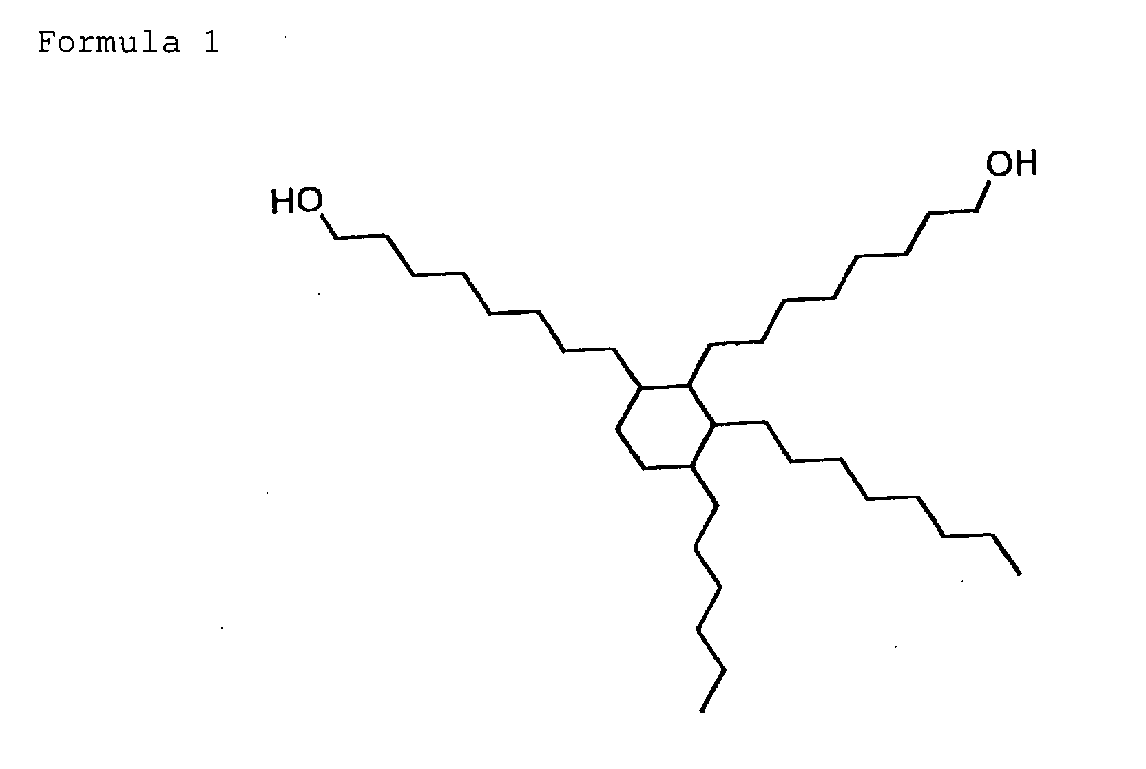
- Diol, which has a ring structure and an alkyl chain whose carbon number is 2 or greater, is preferable in a range of 5 to 60 wt% in the polyurethane resin (C) and further preferably in a range of 10 to 40 wt%. If the diol content is in the above-described ranges, solvent solubility is high and therefore dispersibility is good. Furthermore, durability can be enhanced.
- In the present invention, organic diisocyanate that is caused to react with the above-described polyol to generate polyurethane resin is not particularly limited. Ordinary organic diisocyanate can be employed. Examples are hexamethylenediisocyanate; tridinediisocyanate; isophoronediisocyanate; 1,3-xylilenediisocyanate; 1,4-xylilenediisocyanatecyclohexanediisocyanate; tolidinediisocyanate; 2,4-tolylenediisocyanate; 2,6-tolylenediisocyanate; 4,4'-diphenylmethanediisocyanate; p-phenylenediisocyanate; m-phenylenediisocyanate; 1,5-naphthalenediisocyanate; 3,3-dimethylphenylenediisocyanate; etc.
- By generating polyurethane resin from a monomer which introduces a polar group, polyurethane resin with a polar group can be generated. For example, polyurethane resin with a polar group can be generatedbyamethodof generating it from polar-group contained polyol (such as polyesterpolyol and polyetherpolyol having a polar group), polyole such as polyesterpolyol and polyetherpolyol having no polar group, and diisocyanate, or a method of generating it by changing a portion of a dihydric alcohol or dibasic acid to polar-group contained diol or polar-group contained dibasic acid. The above-described polar-group contained polyol or polar-group contained dibasic acid contains, in the main or side chain of the above-described polyol or dibasic acid, at least one kind of polar group selected from the group consisting of -SO3M, -OSO3M, -P=O(OM)2, -O-P=O(OM)2, and -COOH (where M represents a hydrogen atom, alkali metals, or ammonium) .
- The average molecular weight of polar-group contained polyurethane resin that is employed in the present invention is preferably in a range of 5000 to 100000 and further preferably in a range of 10000 to 50000. If it is 5000 or greater, a magnetic coating is high in physical strength and therefore the durability of the magnetic recording medium can be enhanced. If it is 100000 or less, solubility to a solvent is high and therefore dispersibility can be enhanced. In addition, coating viscosity at a predetermined concentration is suitable and therefore workability is good and handling can be facilitated.
- The polar-group contained polyurethane resin that is employed in the present invention preferably has OH-groups from the viewpoint of hardening properties and durability. The number of OH-groups is preferably in a range of 2 to 40 per molecule and further preferable in a range of 3 to 20 per molecule.
- In the present invention, polyurethane resin other than the above-described polyurethane resin can also be used together.
- Preferably, polyurethane resin to be used together has the same polar group as the above-described polyurethane resin. The above-described chain extender uses polyhydric alcohol, aliphatic alcohol, alicyclic polyamine, aromatic polyamine, etc., which are well known in the prior art. Among them, polyhydric alcohol with a molecular weight of 50 to 500 is preferable. If it is 50 or greater, coating strength is high and therefore durability can be enhanced. If it is 500 or less, the glass transition temperature Tg of a coating is high and therefore the coating becomes hard and durability can be enhanced.
- Polyhydric alcohol can employ a short chain diol such as bisphenol A, bisphenol hydride A, bisphenol S, bisphenol P, an ethylene oxide added to these, a propylene oxide added to these, cyclohexanedimethanol, cyclohexanediol, hydroquinone, bis(2-hydroxyethyl)tetrabromobisphenol A, bis(2-hydroxyethyl)tetrabromobisphenol S, bis(2-hydroxyethyl)tetramethylbisphenol S, bis(2-hydroxyethyl)diphenylbisphenol S, bis(2-hydroxyethyl)diphenylbisphenol, bis(2-hydroxyethyl)thiodiphenol, bis(2-hydroxyethyl)bisphenol F, biphenol, bisphenolfluorene, bisphenolfluorenedihydroxyethylether, etc. Among them, diol, which has aromatic and alicyclic structures, such as bisphenol, bisphenol hydride A, bisphenol S, bisphenol P, ethylene oxide and polypropylene oxide added to these, cyclohexanedimethanol, cyclohexanediol, etc., are preferred.
- While the binder in the present invention employs the above-described polar-group contained polyurethane resin, other resins, such as vinyl chloride resin, acrylic resin, etc., may be used together. Preferably, these resins have at least one kind of polar group selected from the group consisting of -SO3M, -OSO3M, -P=O(OM)2, -O-P=O(OM)2, and -COOH (where M represents a hydrogen atom, an alkali metal ion, or an ammonium ion).
- The resins that can be used together are not particularly limited. Conventional thermoplastic resin, thermosetting resin, reaction type resin, and a mixture of these can be used. Thermoplastic resin that is employed has a glass transition temperature of - 100 to 150 °C and a number average molecular weight of 1000 to 200000, preferably 10000 to 100000. Examples are various rubber resins, and a polymer and a copolymer which contain, as a constituent unit, vinylidene chloride, acrylonitrile, styrene, butadiene, ethylene, vinyl butyral, vinyl acetal, vinyl ester, etc. Examples of thermosetting resin and reaction type resin are phenol resin, phenoxy resin, epoxy resin, urea resin, melamine resin, alkyd resin, acrylic reaction resin, formaldehyde resin, silicon resin, epoxy-polyamide resin, a mixture of polyester resin and isocyanate prepolymer, etc. The above-described resins can be used singly or in combination.
- In the present invention, a binder can be employed in a range of 5 to 50 weight parts with respect to 100 weight parts of ferromagnetic powder or non-magnetic powder. Particularly, if the binder content is in a range of 7 to 45 weight parts, the glossiness of the magnetic layer surface or non-magnetic layer surface becomes high and the dispersibility of ferromagnetic powder or nonmagnetic powder can be enhanced. Furthermore, if the binder content is in a range of 10 to 40 weight parts, the electromagnetic transfer characteristic is considerably improved. If the binder content is less than 5 weight parts, ferromagnetic powder or nonmagnetic powder is not bound. On the other hand, if it is greater than 50 weight parts, dispersibility of ferromagnetic powder or nonmagnetic powder cannot be further enhanced, and in the magnetic layer, a reduction in the fill amount of ferromagnetic powder and a reduction in the electromagnetic transfer characteristic often occur.
- The second flexible magnetic recording medium of the present invention is constructed basically of a magnetic layer and an underlying layer (non-magnetic layer). At least either the underlying layer or magnetic layer may be formed into a multilayer, Therefore, it is possible to change the quantity of the binder, the quantity of polyurethane resin or other resins in the binder, the molecular weight of each resin forming the magnetic layer, and the quantity of the polar group within the scope of the present invention as necessary. Optimization should be performed on each layer, and known techniques relating to multilayer construction can be utilized. When changing the quantity of the binder at each layer, for instance, it is necessary to increase the quantity of the binder of the magnetic layer to reduce flaws in the magnetic layer surface, or it is necessary to increase the quantity of the binder of the underlying layer to give flexibility so that a good head touch is obtained. When a change is made, it is preferable to perform optimization to the extent that the advantages of the present invention are exhibited.
- The second flexible magnetic recording medium of the present invention is basically the same in construction as known magnetic recording media except a predetermined binder employed in the magnetic layer. Among them, a magnetic recording medium can be suitably employed that has a practically non-magnetic layer (underlying layer), and a magnetic layer formed on the non-magnetic layer and having ferromagnetic powder or ferromagnetic hexagonal ferrite powder distributed in a binder. In this magnetic recording medium, the thickness of the magnetic layer can be made 0.5 µm or less. In addition, it has high mechanical strength and is excellent in surface smoothness. Therefore, if this magnetic recording medium is employed, a magnetic recording medium with a high recording density and high durability can be obtained.
- A preferred example of this magnetic recording medium will hereinafter be described in detail.
- A description of the magnetic layer is omitted because it is the same as the contents described in the [Magnetic Layer] of the first flexible magnetic recording medium.
- A description of the ferromagnetic powder is omitted because it is the same as the contents described in the (Ferromagnetic Powder) of the first flexible magnetic recording medium.
- A description of the carbon black in the magnetic layer is omitted because it is the same as the contents described in the (Carbon Black in the Magnetic Layer) of the first flexible magnetic recording medium.
- A description of the non-magnetic layer (underlying layer) is omitted because it is the same as the contents described in the [Non-Magnetic Layer (Underlying Layer)] of the first flexible magnetic recording medium.
- A description of the non-magnetic powder is omitted because it is the same as the contents described in the (Non-Magnetic Powder) of the first flexible magnetic recording medium.
- The underlying layer may contain an abrasive. The abrasive, in addition to the above-described natural and artificial diamonds contained in the magnetic layer, can use molten alumina, silicon carbide, chromium oxide, serium oxide, α-iron oxide, corundum, artificial corundum, silicon nitride, titaniumcarbide, titanium oxide, silicon dioxide, boron nitride, garnet, emery (main ingredients: corundum and magnetic iron ore), etc. If the underlying layer contains an abrasive, the surface shape and the state of protrusion of the abrasive can be controlled.
- A description of the carbon black, etc. in the underlying layer is omitted because it is the same as the contents described in the (Carbon Black, etc. in the Underlying Layer) of the first flexible magnetic recording medium.
- A description of the additives is omitted because it is the same as the contents described in the [Additives] of the first flexible magnetic recording medium.
- A description of the layer construction is omitted because it is the same as the contents described in the [Layer Construction] of the first flexible magnetic recording medium.
- A description of the substrate is omitted because it is the same as the contents described in the [Substrate] of the first flexible magnetic recording medium.
- The method of fabricating the second flexible magnetic recording medium of the present invention includes the preparation of a coating solution for forming each layer, application of the coating solution to the substrate, orientation treatment, drying, cooling, calendering, stamping, post-hardening, polishing, assembly, etc.
- The step of generating the magnetic coating and non-magnetic coating of the magnetic recording medium includes at least a kneading step, a dispersion step, and mixing steps provided before and after these steps as necessary. Each step may be performed in two or more stages. Ferromagnetic powder, non-magnetic powder, a binder, carbon black, an abrasive, an antistatic agent, a lubricant, and a solvent may be added at the beginning or in the middle of any step. In addition, each material may be divided and added in two or more steps. For example, polyurethane may be divided and added in the kneading step, the dispersion step, and the mixing step for adjusting viscosity after dispersion.
- The magnetic coating and non-magnetic coating are kneaded and dispersed by various kneaders. Examples of kneaders are a two-roll mill, a three-roll mill, a ball mill, a pebble mill, a revolving mill, a sand grinder, a szegvari, a high-speed impeller disperser, a high-speed stone mill, a high-speed impact mill, a disperser, a kneader, a high-speed mixer, a homogenizer, an ultrasonic disperser, etc.
- A method for applying a coating solution is not particularly limited. When the non-magnetic layer formed on the substrate by applying a first coating solution for the non-magnetic layer is in a wet state, a second coating solution for the magnetic layer may be applied on the non-magnetic layer (wet-on-wet method). Alternatively, after the first coating solution is dried, the second coating solution may be applied on the non-magnetic layer (wet-on-dry method). In the wet-on-wet method, the magnetic layer is uniform in thickness, defects such as pinholes are prevented, and yield rate is high. In addition, the intimate contact between the non-magnetic layer and the magnetic layer is enhanced and the separation of the magnetic layer from the non-magnetic layer is prevented. In the wet-on-wet method, if the layer coated with the first coating solution for the non-magnetic layer is in a wet state, the second coating solution for the magnetic layer may be applied at the same time as the first coating solution or after the first coating solution. On the other hand, in the wet-on-dry method, a fluctuation in the interface between the magnetic layer and the non-magnetic layer is reduced, and consequently, noise can be prevented and a S/N ratio can be enhanced.
- After drying, a surface smoothing process can be performed on the coating. The surface smoothing process can be performed by super calender rolls, etc. If the surface smoothing process is performed, bores produced by the removal of a solvent during drying are eliminated and the fill amount of the ferromagnetic powder in the magnetic layer is enhanced. As a result, a magnetic recording medium with a high electromagnetic transfer characteristic can be obtained. The calender rolls may be formed from a plastic material, which has a heat resisting property, such as epoxy, polyimide, polyamide, polyimideamide, etc. In the calendering process, the line pressure is in a range of 100 to 500 kg/cm, preferably 200 to 450 kg/cm, and the temperature is in a range of 60 to 130 °C, preferably 80 to 100 °C.
- Now, a second embodiment of the present invention and comparative examples will be described in further detail. Note in the embodiment that the word "part" or "parts" represents "weight part" or "weight parts."
- The materials of a binder, a coating (magnetic coating) for forming a magnetic layer and a coating (non-magnetic coating) for forming a non-magnetic underlying layer were prepared as listed below. The quantity of each ingredient is a quantity per 100 weight parts of ferromagnetic metal powder or non-magnetic powder.
- In a container equipped with a thermometer, a stirrer, and a reflux condenser, nitrogen replacement was performed in advance. In the container, polyetherpolyol of composition listed in Table 2 and short chain diol with a ring structure were dissolved into a cyclohexane-30% solution at 60°C under the flow of nitrogen. Subsequently, 60 ppm of dibutyltinlaurate was added as a catalyst and dissolved for 15 min. Next, an organic diisocyanate compound listed in Table 2 was added and heated for 6 hr. In this way, polyurethane resin PUA-1 was obtained. The hydrophilic polar group content (-SO3Na) of the obtained polyurethane resin PUA-1 was 0.287 meq/g.
- In the same way as polyurethane resin PUA-1, polyurethane resins PUA-2, PUA-3, PUA-4, PUC-1, PUC-2, and PUC-3 were obtained by employing a chain extender and an organic diisocyanate compound listed in Table 2. The hydrophilic polar group of each polyurethane resin, the hydrophilic polar group content, etc., are listed in Table 2.
- 365 parts of adipic acid, 260 parts of neopentylglycol, 2 wt% of zinc acetate, and 3 wt% of sodium acetate were put in a reaction container equipped with a thermometer, a stirrer, and a reflux condenser. Next, an ester exchange reaction was made for 3 hr at 180 to 220°C. Subsequently, a condensation polymerization reaction was made for 2 hr at 220 to 280°C under a reduced pressure of 1 to 10 mmHg. In this manner, polyesterpolyol A was obtained.
- Next, in the same manner as polyurethane resin PUA-1, polyurethane resin PUB-1 was obtained by employing the obtained polyesterpolyol A, a chain extender and an organic diisocyanate compound. The hydrophilic polar group content of the obtained polyurethane resin PUB-1 was 0.824 meq/g.
- In the same manner as polyurethane resin PUB-1, polyurethane resins PUB-2, PUB-3, PUB-4, PUB-5, PUB-6, and PUB-7 were obtained by employing polyesterpolyol, a chain extender and an organic diisocyanate compound listed in Table 2. The hydrophilic polar group of each polyurethane resin, the hydrophilic polar group content, etc., are listed in Table 2.


<Magnetic Coating A> Hexagonal barium ferrite 100 parts Surface treatment: Al2O3 5 wt%, SiO2 2 wt% Hc: 2500 Oe Plate size: 25 nm Plate ratio: 3 σ s: 56 emu/g Vinyl chloride copolymer (MR110: Nippon Zeon) 7 parts Polyurethane resin (UR8200: Toyobo) 3 parts α-alumina (HIT60: Sumitomo Chemical) 4 parts Diamond (average particle size 100 µm) 2 parts Carbon black (#50: Asahi Carbon) 1 part Isocetyl stearate 5 parts Stearic acid 1 part Oleic acid 1 part Methyl ethyl ketone 80parts Cyclohexane 120 parts <Magnetic Coating B> Hexagonal barium ferrite 100 parts Surface treatment: Al2O3 5 wt%, SiO2 2 wt% Hc: 2500 Oe Plate size: 25 nm Plate ratio: 3 σs: 56 emu/g Polyurethane resin PUA-1 10 parts α-alumina (HIT60: Sumitomo Chemical) 4 parts Diamond (average particle size 100 µm) 2 parts Carbon black (#50: Asahi Carbon) 1 part Isocetyl stearate 5 parts Stearic acid 1 part Oleic acid 1 part Methyl ethyl ketone 80 parts Cyclohexane 120 parts <Magnetic Coating C> Ferromagnetic metal powder 100 parts Composition: Fe 70%, Co 30% Hc: 2300 Oe Major axis length: 0.045 µm Crystal size: 120 Å σs: 120 emu/g Sintering preventives: Al compound (Al/Fe: atomic ratio 14%) Y compound (Y/Fe: atomic ratio 7%) Vinyl chloride copolymer (MR110 : Nippon Zeon) 10 parts Polyurethane resin (UR8200: Toyobo) 4parts α-alumina (HIT60: Sumitomo Chemical) 5 parts Diamond (average particle size 0.1 µm) 1 part Carbon black (#50: Asahi Carbon) 1 part Phenylphosphonic acid 3 parts n-butyl stearate 3parts Butoxyethyl stearate 3 parts Ethyleneglycoldiolete 6parts Stearic acid 1 part Oleic acid 1 part Methyl ethyl ketone 140 parts Cyclohexane 200 parts <Magnetic Coating D> Ferromagnetic metal powder 100 parts Composition: Fe 70%, Co 30% Hc: 2300 Oe Major axis length: 0.045 µm Crystal size: 120 Å σs: 120 emu/g Sintering preventives: Al compound (Al/Fe: atomic ratio 14%), Y compound (Y/Fe: atomic ratio 7%) Polyurethane resin PUA-1 10 parts α-alumina (HIT60: Sumitomo Chemical) 5 parts Diamond (average particle size 0.1 µm) 1 part Carbon black (#50: Asahi Carbon) 1 part Phenylphosphonic acid 3 parts n-butyl stearate 3 parts Butoxyethyl stearate 3 parts Ethyleneglycoldiolete 6 parts Stearic acid 1 part Oleic acid 1 part Methyl ethyl ketone 140 parts Cyclohexane 200 parts <Non-magnetic Coating a> Non-magnetic powder: α-Fe2O3 hematite 100 parts Major axis length: 0.07 µm Minor axis length: 0.014 µm Specific surface area by BET: 55 m2/g pH: 9 Surface treatment agent: Al2O3 8 wt% Carbon black 25 parts (average particle size 20nm, SC-U: Colombian Carbon) Vinyl chloride copolymer (MR104 : Nippon Zeon) 15 parts Polyurethane resin (UR5500: Toyobo) 7 parts Phenylphosphonic acid 4 parts Isocetyl stearate 6 parts Oleic acid 1.3 parts Stearic acid 1.3 parts Methyl ethyl ketone/ cyclohexane 250 parts (8/2 mixed solvent) <Non-magnetic Coating b> Non-magnetic powder:α-Fe2O3 hematite 100 parts Major axis length: 0.07 µm Minor axis length: 0.014 µm Specific surface area by BET: 55 m2/g pH: 9 Surface treatment agent: Al2O3 8 wt% Carbon black 25 parts (average particle size 20nm, SC-U: Colombian Carbon) Polyurethane resin PUA-1 22parts Phenylphosphonic acid 4 parts Isocetyl stearate 6 parts Oleic acid 1.3 parts Stearic acid 1.3 parts Methyl ethyl ketone/ cyclohexane (8/2 mixed solvent) 250 parts - The substrate of the master carrier employed a Ni substrate, which was generated by a stamper generation method. More specifically, the disk-shaped Ni substrate has a land/groove pattern, in which radial lines with a width of 0.5 µm are arranged between the disk center and a radial position of 20 to 40 mm, and the line pitch is 0.3 µm at the radially innermost position 20 mm away from the disk center. The Ni substrate has a FeCo30at% layer (soft magnetic layer), which was formed at 25°C. The thickness of the soft magnetic layer is 200 nm, the Ar sputtering pressure is 1.5 × 10⁻⁴ Pa (1.08 mTorr), and the applied voltage is 2.80 W/cm2.
- The ingredients of the magnetic coating A were kneaded with a kneader and dispersed with a sand mill. Similarly, the ingredients of the non-magnetic coating a were kneaded and dispersed. In the dispersed solutions of the magnetic coating A and non-magnetic coating a, 13 parts of polyisocyanate were added to the coating solution of the non-magnetic layer, and 4 parts of polyisocyanate were added to the coating solution of the magnetic layer A. Furthermore, 30 parts of cyclohexane were added to each of the two coating solutions. Next, they were passed through a filter with an average bore diameter of 1 µ m. In this way, the coating solution for the non-magnetic layer and the coating solution for the magnetic layer A were prepared.
- The obtained non-magnetic layer coating solution was applied on the polyethyleneterephthalate substrate of 62 µm in thickness and 3 nm in center line average height so as to have a thickness of 1.5 µm after drying. Immediately after the application of the non-magnetic layer coating solution, the obtained magnetic layer coating solution was applied on the non-magnetic layer coating solution so as to have a thickness of 0.1 µm after drying. After drying, the magnetic medium was treated at a temperature of 90°C and a line pressure of 300 kg/cm with a 7-roll calender. The magnetic medium was stamped out to have a diameter of 3.7 in, and the surface was polished. With the master carrier obtained in the above-described method, signals were transferred magnetically to the obtained magnetic medium.
-
Sample 2 is the same assample 1 except that the polyurethane resin UR8200 in the magnetic coating A is changed to polyurethane resin PUA-1. - Sample 3 is the same as
sample 1 except that the quantity of the vinyl chloride copolymer MR110 in the magnetic coating A is changed from 7 parts to 1.5 parts and the quantity of the polyurethane resin PUA-1 is changed from 3 parts to 8.5 parts. - Sample 4 is the same as
sample 1 except that the magnetic coating B is employed instead of the magnetic coating B and the non-magnetic coating b is employed instead of the non-magnetic coating a. - Samples 5 to 17 are the same as
sample 1 except that polyurethane resin to be added to the magnetic coating and non-magnetic coating is changed as listed in Table 3. - Sample 18 is the same as
sample 1 except that the magnetic coating B is employed instead of the magnetic coating A. - Sample 19 is the same as
sample 1 except that the magnetic coating C is employed instead of the magnetic coating A. - Sample 20 is the same as
sample 1 except that the magnetic coating D is employed instead of the magnetic coating A and the non-magnetic coating b is employed instead of the non-magnetic coating a. -
Samples 21 to 33 are the same assample 1 except that polyurethane resin to be added to the magnetic coating and non-magnetic coating is changed as listed in Table 3. - The kind of binders of the samples, initial S/N ratio, and quality evaluation by the number of signal-transferred sheets are listed in Table 3. The initial S/N ratio and number of transferred sheets in Table 3 were evaluated by the following methods.
- For each of the magnetic media of the obtained
samples 1 to 33, a signal with a bit length of 0.3 µm was magnetically transferred by the generated master carriers. After magnetic transfer, a signal was reproduced from each of the magnetic media with an MR head of 0.5 µm in track width, using a RWA1001 type disk evaluation device (GUZIK) and a spin stand LS-90 (Kyodo Electronic Systems). Thereafter, the S/N ratio of each of the reproduced signals was evaluated. - For each of the magnetic media of the obtained
samples 1 to 33, a signal with a bit length of 0.3 µm was magnetically transferred by the generated master carriers. After magnetic transfer, a signal was reproduced from each of the magnetic media with an MR head of 0.5 µm in track width, using a RWA1001 type disk evaluation device (GUZIK) and a spin stand LS-90 (Kyodo Electronic System). The magnetic transfer to the magnetic recording medium was stopped when the level of the reproduced signal (TAA) was 2dB lower than that of the signal at the starting point. At this time, the number of signal-transferred media was calculated.Sample Magnetic coating Non-magnetic coating Binder Initial S/N (dB) Number of signal-transferred sheets (×10000) Magnetic layer Non-magnetic layer 1 A a MR110+UR8200 MR104+UR5500 20 50 2 A a MR110+PUA1 MR104+UR5500 21 50 3 A a MR110+PUA1 MR104+UR5500 24 100 4 B b PUA-1 PUA-1 26 100< 5 B b PUA-2 PUA-2 26 100< 6 B b PUA-3 PUA-3 24 100< 7 B b PUA-4 PUA-4 20 100< 8 B b PUB-1 PUB-1 20 100< 9 B b PUB-2 PUB-2 26 100< 10 B b PUB-3 PUB-3 28 100< 11 B b PUB-4 PUB-4 26 100< 12 B b PUB-5 PUB-5 28 100< 13 B b PUB-6 PUB-6 28 100< 14 B b PUB-7 PUB-7 28 100< 15 B b PUC-1 PUC-1 26 100< 16 B b PUC-2 PUC-2 24 100< 17 B b PUC-3 PUC-3 20 100< 18 B b PUB-3 MR104+UR5500 24 100 19 C a MR110+UR8200 MR104+UR5500 20 50 20 D b PUA-1 PUA-1 26 100< 21 D b PUA-2 PUA-2 26 100< 22 D b PUA-3 PUA-3 24 100< 23 D b PUA-4 PUA-4 20 100< 24 D b PUB-1 PUB-1 20 100< 25 D b PUB-2 PUB-2 26 100< 26 D b PUB-3 PUB-3 28 100< 27 D b PUB-4 PUB-4 26 100< 28 D b PUB-5 PUB-5 28 100< 29 D b PUB-6 PUB-6 28 100< 30 D b PUB-7 PUB-7 28 100< 31 D b PUC-1 PUC-1 26 100< 32 D b PUC-2 PUC-2 24 100< 33 D b PUC-3 PUC-3 20 100< - It can be understood from the number of signal-transferred sheets in Table 3 that in the magnetic recording media of the present invention (samples 3 to 18 and 20 to 33), in which polyurethane resin having a specific polar group in the magnetic layer by a predetermined amount is contained a predetermined quantity with respect to the quantity of all resins, corrosion of the magnetic master carrier surface is prevented over a long time. In addition, the dispersibility of the magnetic powder in the magnetic layer is enhanced by polyurethane resin having a specific polar group, so a sufficient S/N ratio can be obtained.
- On the other hand, in
sample 2 where the quantity of the polyurethane resin with a specific polar group is as low as 30 wt% andsamples 1 and 19 which has no polyurethane resin having a specific polar group, the number of signal-transferred sheets is half that of the magnetic recording medium of the present invention and it is contemplated that corrosion has occurred in the master carrier surface. - As described above, in the second magnetic recording medium of the present invention, the magnetic recording layer contains a predetermined quantity of polyurethane resin that has a specific polar group by a predetermined quantity. However, it can be understood from the comparison between the
samples 10 and 18 that if the non-magnetic layer also contains the polyurethane resin, corrosion of the master carrier surface can be prevented over a longer time. - As set forth above, in the second flexible magnetic recording medium of the present invention, the magnetic layer includes polyurethane resin which contains in a range of 0.05 to 0.7 meq/g at least one kind of polar group selected from the group consisting of -SO3M, -OSO3M, -P=O(OM)2, -O-P=O(OM)2, and -COOH (where M represents a hydrogen atom, alkali metals, or an ammonium salt) . The polyurethane resin content is 60 wt% or greater of the quantity of all resins in the magnetic layer. Therefore, it becomes possible to achieve the long-term stability of the quality of signals recorded on the magnetic recording medium. In addition, polyurethane resin with a high polar group content is employed a predetermined quantity or greater. Therefore, it becomes possible to obtain a sufficient S/N ratio.
- Now, a description will be given of a third flexible magnetic recording medium. The third flexible magnetic recording medium is a flexible magnetic recording medium to which data is transferred by being brought into intimate contact with a master carrier which has a land/groove pattern corresponding to said data. The third magnetic recording medium comprises a non-magnetic substrate, and a non-magnetic layer, and a magnetic layer. The non-magnetic layer and the magnetic layer are coated on the substrate in the recited order. The relationship between the Moh's hardness (X) of the surface of the master carrier and the Knoop hardness (Y kg/mm2) of the surface of the magnetic recording medium is represented as 1 ≦ Y/X ≦ 7.
- The relationship between the Moh's hardness (X) of the surface of the master carrier and the Knoop hardness (Y kg/mm2) of the surface of the magnetic recording medium is in a range of 1 ≦ Y/X ≦ 7, preferably 2 ≦ Y/X ≦ 5. In the case where Y/X is less than 1 or greater than 8, magnetic transfer cannot be performed in a good state of contact with the master carrier and it is difficult to enhance signal quality. In addition, in the case where Y/X is greater than 8, flaws will occur in the master carrier if magnetic transfer is repeatedly performed. Consequently, a sufficient number of magnetic recording media cannot be obtained.
- In the third magnetic recording medium, the Knoop hardness of the surface is adjusted according the Moh's hardenss of the master carrier surface so that it is in a range of 1 ≦ Y/X ≦ 7. For instance, to make the Knoop hardness of the surface of the magnetic recording medium greater, it is necessary to enhance the bridge density of a coating by increasing the quantity of a hardening agent to be added to the underlying layer and magnetic layer of the magnetic recording medium, to employ a binder whose glass transition temperature Tg is high, or to enhance the fill density of the magnetic substance in the surface of the magnetic recording medium by increasing the temperature and pressure in a calendering treatment. However, the material of the magnetic recording medium and the fabrication method are not particularly limited as long as the relationship of 1 ≦ Y/X ≦ 7 is obtained.
- As a preferred example, a description will be given of a magnetic recording medium that has a practically non-magnetic layer (underlying layer), and a magnetic layer formed on the non-magnetic layer and having ferromagnetic powder or ferromagnetic hexagonal ferrite powder distributed in a binder. In this magnetic recording medium, the thickness of the magnetic layer can be made 0.5 µm or less. In addition, it has high mechanical strength and is excellent in surface smoothness. Therefore, if this magnetic recording medium is employed, a magnetic recording medium with a high recording density and high durability can be obtained.
- A description of the magnetic layer is omitted because it is the same as the contents described in the [Magnetic Layer] of the first flexible magnetic recording medium.
- A description of the ferromagnetic powder is omitted because it is the same as the contents described in the (Ferromagnetic Powder) of the first flexible magnetic recording medium.
- The magnetic layer of the magnetic recording medium may contain known abrasives. Among them, diamond and alumina particles are preferred. Abrasives other than the above-described abrasives may be used together. Such abrasives are silicon carbide, chromium oxide, serium oxide, α-iron oxide, corundum, silicon nitride, titanium carbide, titanium oxide, silicon dioxide, boron nitride, etc. These abrasives with a Moh' s hardness of 6 or greater can be employed singly or in combination. These abrasives may be added to the underlying layer as necessary. If an abrasive is added to the underlying layer, the surface shape can be controlled, or the state of protrusion of the abrasive can be controlled. The particle size and quantity of an abrasive that is added to the magnetic layer and underlying layer should be set to optimum values.
- A description of the carbon black in the magnetic layer is omitted because it is the same as the contents described in the (Carbon Black in the Magnetic Layer) of the first flexible magnetic recording medium.
- A description of the non-magnetic layer (underlying layer) is omitted because it is the same as the contents described in the [Non-Magnetic Layer (Underlying Layer)] of the first flexible magnetic recording medium.
- A description of the non-magnetic powder is omitted because it is the same as the contents described in the (Non-Magnetic Powder) of the first flexible magnetic recording medium.
- A description of the carbon black, etc. in the underlying layer is omitted because it is the same as the contents described in the (Carbon Black, etc. in the Underlying Layer) of the first flexible magnetic recording medium.
- A description of the binders is omitted because it is the same as the contents described in the [Binders] of the first flexible magnetic recording medium.
- A description of the additives is omitted because it is the same as the contents described in the [Additives] of the first flexible magnetic recording medium.
- Note that the whole or part of an additive may be added in any step of fabricating magnetic and non-magnetic coatings. In addition, after formation of the magnetic layer, the whole or part of an additive may be applied at the same time or in order, depending on the object.
- A description of the layer construction is omitted because it is the same as the contents described in the [Layer Construction] of the first flexible magnetic recording medium.
- A description of the substrate is omitted because it is the same as the contents described in the [Substrate] of the first flexible magnetic recording medium.
- The method of fabricating the fourth flexible magnetic recording medium of the present invention includes the preparation of a coating solution for forming each layer, application of the coating solution to the substrate, orientation treatment, drying, cooling, calendering, stamping, post-hardening, polishing, assembly, etc.
- The step of generating the magnetic coating and non-magnetic coating of the magnetic recording medium includes at least a kneading step, a dispersion step, and mixing steps provided before and after these steps as necessary. Each step may be performed in two or more stages. Ferromagnetic powder, non-magnetic powder, a binder, carbon black, an abrasive, an antistatic agent, a lubricant, and a solvent may be added at the beginning or in the middle of any step. In addition, each material may be divided and added in two or more steps. For example, polyurethane may be divided and added in the kneading step, the dispersion step, and the mixing step for adjusting viscosity after dispersion.
- The magnetic coating and non-magnetic coating are kneaded and dispersed by various kneaders. Examples of kneaders are a two-roll mill, a three-roll mill, a ball mill, a pebble mill, a revolving mill, a sand grinder, a szegvari, a high-speed impeller disperser, a high-speed stone mill, a high-speed impact mill, a disperser, a kneader, a high-speed mixer, a homogenizer, an ultrasonic disperser, etc.
- A method for applying a coating solution is not particularly limited. It is preferable to apply a non-magnetic layer coating solution on a substrate, dry the solution, and apply a magnetic layer coating solution. Such a sequential multiple application method, that is, a wet-on-dry method, can employ a conventional one. Preferred examples are methods disclosed in Japanese Unexamined Patent Publication Nos. 3(1991)-214417 and 3(1991)-214422.
- A surface smoothing process can be performed by a calender, etc. The calender rolls may be formed from a plastic material, which has a heat resisting property, such as epoxy, polyimide, polyamide, polyimideamide, etc. In the calendering process, the line pressure is in a range of 50 to 500 kg/cm, preferably 100 to 400 kg/cm, and the temperature is in a range of 20 to 130 °C, preferably 40 to 120 °C.
- The master carrier that is employed in performing magnetic transfer is a conventional one. The construction, material, and fabrication method of the master carrier are not limited.
- Now, a third embodiment of the present invention will be described in further detail. Note in the embodiment that the word "part" or "parts" represents "weight part" or "weight parts."
- The substrate of a master carrier employed a Ni substrate, which was generated by a stamper generation method. More specifically, the disk-shaped Ni substrate has a land/groove pattern, in which radial lines with a width of 0.5 µm are arranged between the disk center and a radial position of 20 to 40 mm, and the line pitch is 0.3 µm at the radially innermost position 20 mm away from the disk center.
- The Ni substrate has a FeCo30at% layer (soft magnetic layer), which was formed at 25°C. The layer thickness of the soft magnetic layer is 200 nm, the Ar sputtering pressure is 1.5 × 10⁻⁴ Pa (1.08 mTorr), and the applied voltage is 2.80 W/cm2. The Moh's hardness of the surface of the master carrier obtained is 4.
- In the master carrier of sample A, the surface was treated with an oxygen plasma to obtain a Moh's hardness of 6. The oxygen partial pressure is 7.5 × 10⁻⁵ Pa (0.54 mTorr).
- In the master carrier of sample A, the surface was provided with a diamond-like carbon (DLC) coating to obtain a Moh's hardness of 9.5.
- The materials of a coating (magnetic coating) for the magnetic layer and a coating (non-magnetic coating) for the non-magnetic underlying layer were prepared as listed below. The quantity of each ingredient is a quantity per 100 weight parts of ferromagnetic metal powder or non-magnetic powder.
<Magnetic Coating A> Hexagonal barium ferrite 100 parts Surface treatment: Al2O3 5 wt%, SiO2 2 wt% Hc: 3000 Oe Plate size: 25 nm Plate ratio: 3 σs: 56 emu/g Vinyl chloride copolymer (MR110:Nippon Zeon) 6 parts Polyurethane resin (UR8200: Toyobo) 3parts α-alumina (HIT60: Sumitomo Chemical) 5parts Diamond (average particle size 0.15 µm) 1 part Carbon black (#50: Asahi Carbon) 1 part Isocetyl stearate 5 parts Stearic acid 1 part Oleic acid 1 part Methyl ethyl ketone 80parts Cyclohexane 120 parts <Magnetic Coating B> Ferromagnetic metal powder 100 parts Composition: Fe 70%, Co 30% Hc: 2300 Oe Major axis length: 0.045 µm Crystal size: 120 Å σs: 150 emu/g Sintering preventives: Al compound (Al/Fe: atomic ratio 14%), Y compound (Y/Fe: atomic ratio 7%) Vinyl chloride copolymer (MR110 : Nippon Zeon) 10 parts Polyurethane resin (UR8200: Toyobo) 4 parts α-alumina (HIT60: Sumitomo Chemical) 5 parts Diamond (average particle size 0.15 µm) 1 part Carbon black (#50: Asahi Carbon) 1 part Phenylphosphonic acid 3 parts Isocetyl stearate 5 parts Stearic acid 1 part Oleic acid 1 part Methyl ethyl ketone 140 parts Cyclohexane 200 parts <Non-magnetic Coating> Non-magnetic powder: TiO2 crystal rutile 100 parts Average primary particle size: 0.035 µm Specific surface area by BET: 40 m2/g pH: 7; TiO2 content: 90% or greater DBP oil absorption 27 to 38 ml/100g Surface treatment agent: Al2O3, SiO2 Carbon black (EC) 13parts Vinyl chloride copolymer (MR110: Nippon Zeon) 17 parts Polyurethane resin (UR8600: Toyobo) 6parts Phenylphosphonic acid 3 parts Isocetyl stearate 6 parts Oleic acid 1 part Stearic acid 1 part Methyl ethyl ketone 120 parts Cyclohexane 180 parts - The ingredients of the magnetic coating A were kneaded with a kneader and dispersed with a sand mill. Similarly, the ingredients of the non-magnetic coating were kneaded and dispersed. In the dispersed solutions of the magnetic coating A and non-magnetic coating, 13 parts of polyisocyanate were added to the coating solution of the non-magnetic layer, and 4 parts of polyisocyanate were added to the coating solution of the magnetic layer A. Furthermore, 30 parts of cyclohexane were added to each of the two coating solutions. Next, they were passed through a filter with an average bore diameter of 1 µm. In this way, the coating solution for the non-magnetic layer and the coating solution for the magnetic layer A were prepared.
- The obtained non-magnetic layer coating solution was applied on the polyethyleneterephthalate substrate of 62 µm in thickness and 3 nm in center line average height so as to have a thickness of 1.5 µm after drying. After the application of the non-magnetic layer coating solution, the obtained magnetic layer coating solution was applied on the non-magnetic layer coating solution so as to have a thickness of 0.1 µm after drying. After drying, the magnetic medium was treated at a temperature of 90°C and a line pressure of 300 kg/cm with a 7-roll calender. The magnetic medium was stamped out to have a diameter of 3.7 in, and the surface was polished. In this way, a 3.7-in magnetic recording medium was obtained.
- Sample 2 (magnetic recording medium) is the same as
sample 1 except that 2 parts of polyisocyanate is added to the magnetic coating A and 4 parts of polyisocyanate is added to the non-magnetic coating. - Sample 3 (magnetic recording medium) is the same as
sample 1 except that 10 parts of polyisocyanate is added to the magnetic coating A and 20 parts of polyisocyanate is added to the non-magnetic coating. - Sample 4 (magnetic recording medium) is the same as
sample 1 except that the temperature in the calendering treatment is changed to 70°C. - Sample 5 (magnetic recording medium) is the same as
sample 1 except that the temperature in the calendering treatment is changed to 100°C. - Sample 6 (magnetic recording medium) is the same as
sample 1 except that the magnetic coating A is changed to the magnetic coating B. - Sample 7 (magnetic recording medium) is the same as sample 6 except that 2 parts of polyisocyanate is added to the magnetic coating B and 4 parts of polyisocyanate is added to the non-magnetic coating.
- Sample 8 (magnetic recording medium) is the same as sample 6 except that 10 parts of polyisocyanate is added to the magnetic coating B and 20 parts of polyisocyanate is added to the non-magnetic coating.
- The obtained master carriers A to C and
samples 1 to 8 are combined as listed in Table 4, and a signal with a bit length of 0.3 µm was magnetically transferred. The Knoop hardnes Y of the surface of the sample, Moh's hardness X of the master carrier, Y/X, S/N ratio, and the number of signal-transferred sheets are listed in Table 4. The S/N ratio and number of transferred sheets in Table 4 were evaluated by the following methods. - The magnetically transferred signal with a bit length of 0.3 µm was reproduced with an MR head of 0.5 µm in track width, using a RWA1001 type disk evaluation device (GUZIK) and a spin stand LS-90 (Kyodo Electronic Systems). Thereafter, the S/N ratio was evaluated.
- For each of the magnetic media of the
samples 1 to 8 having a signal with a bit length of 0.3 µm, a servo signal was magnetically transferred. The magnetic transfer to the magnetic recording medium was stopped when the level of the reproduced servo signal was 2dB lower than that of the signal at the starting point. At this time, the number of signal-transferred media was calculated.Level Master carrier Magnetic recording medium Y/X value S/N (dB) Number of signal-transferred sheets (×10000) Sample Moh's hardness Sample Knoop hardness (Y) (kg/mm2) 1 B 6 1 20 3.3 28 100< 2 B 6 2 10 1.7 29 100< 3 B 6 3 45 7.5 20 50 4 B 6 4 15 2.5 28 100< 5 B 6 5 40 6.7 26 100< 6 B 6 6 25 4.2 27 100< 7 B 6 7 15 2.5 28 100< 8 B 6 8 50 8.3 16 30 9 A 4 1 20 5.0 27 100< 10 A 4 2 10 2.5 28 100< 11 A 4 3 45 11.3 20 20 12 A 4 4 15 3.8 27 100< 13 A 4 5 40 10.0 22 30 14 C 9.5 1 20 2.1 30 100< 15 C 9.5 2 10 1.1 30 100< 16 C 9.5 3 45 4.7 28 100< 17 C 9.5 4 15 1.6 29 100< 18 C 9.5 5 40 4.2 28 100< - It can be understood from the number of signal-transferred sheets in Table 4 that in the magnetic recording media of the present invention (
levels - On the other hand, in the magnetic recording media (levels 3, 8, 11, and 13) where Y/X is greater than the above-described range, the contact between the master carrier and the magnetic recording medium is not sufficient. As a result, signal dropouts occurred during magnetic transfer. Sufficient signal quantity and a sufficient S/N ratio were not obtained.
- As set forth above, in the above-described third flexible magnetic recording medium, the relationship between the Moh's hardness (X) of the surface of the master carrier and the Knoop hardness (Y kg/mm2) of the surface of the magnetic recording medium is represented as 1 ≦ Y/X ≦ 7. Therefore, the intimate contact between the master carrier and the magnetic recording medium can be made sufficient. As a result, signal dropouts can be prevented from occurring in magnetic data transferred to the magnetic recording medium, and signal quantity can be enhanced.
- Now, a description will be given of a fourth flexible magnetic recording medium. In the fourth flexible magnetic recording medium, a first coating solution for forming the non-magnetic layer contains a first lubricant in a range of 1 to 20 wt% of non-magnetic powder contained in the non-magnetic layer. A second coating solution for forming the magnetic layer contains a second lubricant which is 1/4 or less of the first lubricant in quantity. The first and second lubricants are liquids at a temperature at which the magnetic transfer is performed.
- The temperature at which the magnetic transfer is performed is 20 to 25°C. The above-described lubricants are not limited if they are liquids at the above-described temperature. For example, fatty acid ester is preferable.
- Fatty acid ester can employ fatty acid esters, which consist of monobasic fatty acids of
carbon numbers 10 to 20 and monohydric alcohols of carbon numbers 3 to 12. - Examples of alcohols that are used as the material of fatty acid ester is monohydric alcohol (such as ethanol, butanol, phenol, benzyl alcohol, 2-methyl butyl alcohol, 2-hexyl decil alcohol, propylene glycol monobutyl ether, ethylene glycol monobutyl ether, dipropylene glycol monobutyl ether, diethylene glycol monobutyl ether, s-butyl alcohol, etc.), and polyhydric alcohol (such as ethylene glycol, diethylene glycol, neopentyl glycol, glycerin, and sorbitan derivatives).
- Examples of fatty acids are acetic acid, propionic acid, octanoic acid, 2-ethyl hexanoic acid, lauric acid, myristic acid, stearic acid, palmitic acid, behenic acid, arachic acid, oleic acid, linoleic acid, linolenic acid, elaidic acid, aliphatic carboxylic acid such as palmitoleic acid, and a mixture of them.
- Examples of fatty acid esters are butyl stearate, s-butyl stearate, isopropyl stearate, butyl oleate, amyl stearate, 3-methyl butyl stearate, 2-ethyl hexyl stearate, 2-hexyl decil stearate, butyl palmitato, 2-ethyl hexyl myristate, a mixture of butyl stearate and butyl palmitato, butoxy ethyl stearate, 2-butoxy-1-propyl stearate, dipropylene glycol monobutyl ether acylated with stearic acid, diethyl glycol dipalmitato, hexamethylenediol acylated with myristic acid and diesterified, and ester compounds such as an oleate of glycerin.
- When magnetic recording media are used under high humidity, the hydrolysis of fatty acid ester often occurs. To alleviate this hydrolysis, it is preferable to select the isometric structure and branch position, such as the branch, straight chain, cis-trans, etc., of fatty acid and alcohol.
- An organic solvent that is employed in the present invention can use, at an arbitrary ratio, ketones (such as acetone, methyl ethyl ketone, diisobutyl ketone, cyclohexanon, isoboron, and tetrohydrofuran); alcohols (such as methanol, ethanol, propanol, butanol, isobutyl alcohol, isopropyl alcohol, and methyl cyclohexanol); esters (such as methyl acetate, butyl acetate, isobutyl acetate, isopropyl acetate, ethyl lactate, and glycol acetate) ; glycol ether systems (such as glycol dimethyl ether, glycol monoethyl ether, dioxane); aromatic hydrocarbons (such as benzen, toluene, xylene, cresol, and chlorobenzen); chlorinated hydrocarbons (such as methylene chloride, ethylene chloride, carbon tetrachloride, chloroform, ethylene chlorohydrin, and dichlorobenzen); N,N-dimethyl formaldehyde; hexane; and so on. These organic solvents do not always need to be 100% pure. The organic solvents, in addition to their main ingredient, may contain impurities such as a metamer, an unreacted product, a side reaction production, a decomposition product, an oxide, moisture, etc. These impurities are preferably 30 wt% or less and further preferably 10 wt% or less.
- The organic solvent that is employed in the present invention may vary in kind and quantity between the magnetic layer and the non-magnetic layer. For instance, the magnetic layer may contain a solvent with a high volatility to enhance surface stability. The non-magnetic layer may contain a solvent with a high surface tension (cyclohexane, dioxane, etc.) to enhance the stability of a coating, or may contain a solvent with a high solubility to increase its fill amount.
- The fourth magnetic recording medium of the present invention is basically the same in construction as known magnetic recording media except that the above-described lubricant is contained in the magnetic layer and non-magnetic layer by a predetermined quantity. Among them, a magnetic recording medium can be suitably employed that has a practically non-magnetic layer (underlying layer), and a magnetic layer formed on the non-magnetic layer and having ferromagnetic powder or ferromagnetic hexagonal ferrite powder distributed in a binder. In this magnetic recording medium, the thickness of the magnetic layer can be made 0.5 µm or less. In addition, it has high mechanical strength and is excellent in surface smoothness. Therefore, if this magnetic recording medium is employed, a magnetic recording medium with a high recording density and high durability can be obtained.
- A preferred example of this magnetic recording medium will hereinafter be described in detail.
- A description of the magnetic layer is omitted because it is the same as the contents described in the [Magnetic Layer] of the first flexible magnetic recording medium.
- A description of the ferromagnetic powder is omitted because it is the same as the contents described in the (Ferromagnetic Powder) of the first flexible magnetic recording medium.
- A description of the abrasives is omitted because it is the same as the contents described in the (Abrasives) of the third flexible magnetic recording medium.
- A description of the carbon black in the magnetic layer is omitted because it is the same as the contents described in the (Carbon Black in the Magnetic Layer) of the first flexible magnetic recording medium.
- A description of the non-magnetic layer (underlying layer) is omitted because it is the same as the contents described in the [Non-Magnetic Layer (Underlying Layer)] of the first flexible magnetic recording medium.
- A description of the non-magnetic powder is omitted because it is the same as the contents described in the (Non-Magnetic Powder) of the first flexible magnetic recording medium.
- A description of the carbon black, etc. in the underlying layer is omitted because it is the same as the contents described in the (Carbon Black, etc. in the Underlying Layer) of the first flexible magnetic recording medium.
- A description of the binders is omitted because it is the same as the contents described in the [Binders] of the first flexible magnetic recording medium.
- A description of the additives is omitted because it is the same as the contents described in the [Additives] of the first flexible magnetic recording medium.
- The magnetic layer and underlying layer of the magnetic recording medium, in addition to the aforementioned lubricants, may contain a wide variety of additives having an static charge prevention effect, a dispersion effect, a plastic effect, etc. Examples are silicon oil; silicon oil with a polar group; fatty acid modified silicon; fluorine-contained silicon; fluorine-contained alcohol; fluorine-contained ester; polyolefin; polyglycol; alkylphosphate and an alkali metal salt thereof; alkylsalfate and an alkali metal salt thereof; polyphenylether; phenylphosphonic acid; α-naphthyphosphoric acid; phenylphosphoric acid; diphenylphosphoric acid; p-ethylbenzenphosphonic acid; phenylhosphinic acid; aminoquinones; various silane coupling agent; titan coupling agent; and fluorine-contained alkylsalfate and an alkali metal salt thereof.
- All or some of the above-described additives may be added in the step of generating magnetic and non-magnetic coatings. For example, there are a case where additives are mixed with a magnetic substance before a kneading step, a case where additives are added in a step of kneading a magnetic substance, a binder, and an organic solvent, a case where additives are added in a dispersion step, a case where additives are added after dispersion, and a case where additive are added immediately before coating. In addition, after formation of the magnetic layer, all or some of additives may be used at the same time or in sequence, depending on the objects.
- A description of the layer construction is omitted because it is the same as the contents described in the [Layer Construction] of the first flexible magnetic recording medium.
- A description of the substrate is omitted because it is the same as the contents described in the [Substrate] of the first flexible magnetic recording medium.
- The method of fabricating the second flexible magnetic recording medium of the present invention includes the preparation of a coating solution for forming each layer, application of the coating solution to the substrate, orientation treatment, drying, cooling, calendering, stamping, post-hardening, polishing, assembly, etc.
- The step of generating the magnetic coating and non-magnetic coating of the magnetic recording medium includes at least a kneading step, a dispersion step, and mixing steps provided before and after these steps as necessary. Each step may be performed in two or more stages. Ferromagnetic powder, non-magnetic powder, a binder, carbon black, an abrasive, an antistatic agent, a lubricant, and a solvent may be added at the beginning or in the middle of any step. In addition, each material may be divided and added in two or more steps. For example, polyurethane may be divided and added in the kneading step, the dispersion step, and the mixing step for adjusting viscosity after dispersion.
- The magnetic coating and non-magnetic coating are kneaded and dispersed by various kneaders. Examples of kneaders are a two-roll mill, a three-roll mill, a ball mill, a pebble mill, a revolving mill, a sand grinder, a szegvari, a high-speed impeller disperser, a high-speed stone mill, a high-speed impact mill, a disperser, a kneader, a high-speed mixer, a homogenizer, an ultrasonic disperser, etc.
- A method for applying a coating solution is not particularly limited. In a preferred method, a first coating solution for the non-magnetic layer is first applied on the substrate to form a non-magnetic layer. After the non-magnetic layer is dried, a second coating solution for the magnetic layer is applied on the non-magnetic layer (i.e., wet-on-wet application). Then, drying is performed and a surface formation treatment is performed. In the wet-on-wet application method, the thickness of the magnetic layer can be made uniform.
- The surface formation treatment can be performed by a calender. The calender rolls are formed from a plastic material, which has a heat resisting property, such as epoxy, polyimide, polyamide, polyimideamide, etc. The line pressure is in a range of 50 to 500 kg/cm, preferably 100 to 400 kg/cm. The temperature is in a range of 20 to 130 °C, preferably 40 to 120 °C.
- Next, a description will be given of a method for pre-formatting a magnetic recording medium by magnetic transfer, utilizing a master carrier. As shown in Fig. 2A, an initializing field Hin is first applied to a
magnetic recording medium 1 in one direction along the direction of the data track to perform initial magnetization. Next, as shown in Fig. 2B, the magnetic recording surface of themagnetic recording medium 1 and the softmagnetic layer 22 of the microscopic land/groove pattern of themetal disk 21 of amaster carrier 2 are brought into intimate contact with each other. In this state, a transfer field Hdu is applied in the opposite direction from the direction of the initializing direction to perform magnetic transfer. As a result, as shown in Fig. 2C, data corresponding to the land/groove pattern of themaster carrier 2 is transferred magnetically to the recording surface (data track) of themagnetic recording medium 1. Such a magnetic transfer method is disclosed, for example, in Japanese Unexamined Patent Publication No. 11(1999)-117800. - It is preferable that the preformatted magnetic recording medium be treated with heat. For example, the preformatted magnetic recording medium is held for 1 to 96 hours (preferably 24 to 48 hours) at temperatures in a range of 30 to 120°C (preferably 50 to 100°C) after magnetic transfer. With such a heat treatment, the lubricant contained in the non-magnetic layer is easily moved to the surface (magnetic layer) of the magnetic recording medium, and therefore, the durability and flaw-resisting property of the magnetic recording medium can be enhanced. After data is magnetically transferredby the master carrier, a lubricant is moved to the surface (magnetic layer) of the magnetic recording medium. As a result, the lubricant in the magnetic recording medium is prevented from being moved to the master carrier, and the long-term stability of the quality of signals recorded on the magnetic recording medium can be achieved. With the lubricant moved to the magnetic layer, the object of enhancing the durability and flaw-resisting property of the magnetic recording medium can be achieved.
- Now, a fourth embodiment of the present invention and comparative examples will be described in further detail. Note in the embodiment that the word "part" or "parts" represents "weight part" or "weight parts."
- The materials of a coating (magnetic coating) for the magnetic layer and a coating (non-magnetic coating) for the non-magnetic underlying layer were prepared as listed below. The quantity of each ingredient is a quantity per 100 weight parts of ferromagnetic metal powder or non-magnetic powder.
<Magnetic Coating A> Ferromagnetic metal powder 100 parts Composition: Fe 70%, Co 30% Hc: 2300 Oe Major axis length: 0.045 µm Crystal size: 120 Å σs: 150 emu/g Sintering preventives: Al compound (Al/Fe: atomic ratio 14%), Y compound (Y/Fe: atomic ratio 7%) Vinyl chloride copolymer (MR110: Nippon Zeon) 10 parts Polyurethane resin (UR8200: Toyobo) 4 parts α-alumina (HIT60: Sumitomo Chemical) 5 parts Diamond (particle size 0.15 µm) 1 part Carbon black (#50: Asahi Carbon) 1 part Phenylphosphonic acid 3 parts Isocetyl stearate 5 parts Stearic acid 1 part Oleic acid 1 part Methyl ethyl ketone 140 parts Cyclohexane 200 parts <Magnetic Coating B> Hexagonal barium ferrite 100 parts Surface treatment: Al2O3 5 wt%, SiO2 2 wt% Hc: 3000 Oe Plate size: 25 nm Plate ratio: 3 σs: 56 emu/g Vinyl chloride copolymer (MR110: Nippon Zeon) 6parts Polyurethane resin (UR8200: Toyobo) 3parts α-alumina (HIT60: Sumitomo Chemical) 5parts Diamond (average particle size 0.1 µm) 1 part Carbon black (#50: Asahi Carbon) 1 part Isocetyl stearate 5 parts Stearic acid 1 part Oleic acid 1 part Methyl ethyl ketone 80parts Cyclohexane 120 parts <Non-magnetic Coating> Non-magnetic powder: TiO2 crystal rutile 100 parts Average primary particle size: 0.035 µm Specific surface area by BET: 40 m2/g pH: 7; TiO2 content: 90% or greater DBP oil absorption 27 to 38 ml/100g Surface treatment agent: Al2O3, SiO2 Carbon black (EC) 13 parts Vinyl chloride copolymer (MR110: Nippon Zeon) 17 parts Polyurethane resin (UR8600: Toyobo) 6parts Phenylphosphonic acid 3 parts Isocetyl stearate 6parts Oleic acid 1 part tearic acid 1 part Methyl ethyl ketone 120 parts Cyclohexane 180 parts - The substrate of the master carrier employed a Ni substrate, which was generated by a stamper generation method. More specifically, the disk-shaped Ni substrate has a land/groove pattern, in which radial lines with a width of 0.5 µm are arranged between the disk center and a radial position of 20 to 40 mm, and the line pitch is 0.3 µm at the radially innermost position 20 mm away from the disk center. The Ni substrate has a FeCo 30 at% layer (soft magnetic layer), which was formed at 25°C. The thickness of the soft magnetic layer is 200 nm, the Ar sputtering pressure is 1.5 × 10⁻⁴ Pa (1.08 mTorr), and the applied voltage is 2.80 W/cm2.
- The ingredients of the magnetic coating A were kneaded with a kneader and dispersed with a sand mill. Similarly, the ingredients of the magnetic coating B and the ingredients of the non-magnetic coating were kneaded and dispersed. In the dispersed solutions of the magnetic coatings A and B and the non-magnetic coating, 13 parts of polyisocyanate were added to the coating solution of the non-magnetic layer, and 4 parts of polyisocyanate were added to the coating solution of the magnetic layer A. 5 parts of polyisocyanate were added to the coating solution of the magnetic layer B. Furthermore, 30 parts of cyclohexane were added to each of the three coating solutions. Next, they were passed through a filter with an average bore diameter of 1 µm. In this way, the coating solution for the non-magnetic layer and the coating solutions for the magnetic layers A and B were prepared.
- The non-magnetic layer coating solution, obtained on the polyethyleneterephthalate substrate of 62 µm in thickness and 3 nm in center line average height, was applied to have a thickness of 1.5 µm after drying. After drying, the obtained magnetic layer coating solutions were sequentially applied on the non-magnetic layer coating solution so as to obtain a thickness of 0.1 µm after drying. After drying, the magnetic medium was treated at a temperature of 90°C and a line pressure of 300 kg/cm with a 7-roll calender. The magnetic medium was stamped out so as to have a diameter of 3.7 in, and the surface was polished. With a magnetic transfer device described below, a servo signal was transferred magnetically to the obtained magnetic medium. After magnetic transfer, the medium was inserted into a 3.7-in cartridge with a liner installed inside (Zip-disk cartridge produced by Iomega), and predetermined mechanical parts were operated. In this way, a 3.7-in magnetic recording medium (disk) was obtained.
-
Samples 2 to 11 are the same assample 1 except the quantity of isocetylstearate added to the magnetic coating A and the non-magnetic coating, listed in Table 5. - Samples 12 to 15 are the same as
sample 1 except that isocetylstearate to be added to the magnetic coating A and the non-magnetic coating is changed to fatty acid ester listed in Table 5 and the described quantities are added. - Sample 16 is the same as
sample 1 except that heat treatment after magnetic transfer is not performed. - Sample 17 is the same as
sample 1 except that the temperature in the heat treatment after magnetic transfer is changed to 70°C. - Sample 18 is the same as
sample 1 except that the magnetic coating A is changed to the magnetic coating B. - Samples 19 to 28 are the same as
sample 1 except the quantity of isocetylstearate added to the magnetic coating A and the non-magnetic coating, listed in Table 5. - The kind and quantity of fatty acid ester in the magnetic layer and non-magnetic layer in the samples, heat treatment conditions, quality evaluation by the number of signal-transferred sheets, and durability are listed in Table 5. The number of signal-transferred sheets and running durability were evaluated by the following methods.
- For each of the samples having a signal of line recording density 90 KFCI by the magnetic transfer device in the above-described method, a servo signal was continuously transferred. The magnetic transfer to the magnetic recording medium was stopped when the level of the reproduced servo signal was 2dB lower than that of the signal at the starting point. At this time, the number of signal-transferred media was calculated.
- For each of the magnetic media of the obtained
samples 1 to 28, a signal with a bit length of 0.3 µm was transferred by the generated master carrier. After magnetic transfer, a signal was reproduced from each of the magnetic media with an MR head of 0.5 µm in track width, using a RWA1001 type disk evaluation device (GUZIK) and a spin stand LS-90 (Kyodo Electronic Systems) . The magnetic transfer to the magnetic recording medium was stopped when the level of the reproduced signal (TAA) was 2dB lower than that of the signal at the starting point. At this time, the number of signal-transferred media was calculated.Sample Magnetic coating kind Fatty acid ester in the magnetic layer Fatty acid ester in the non-magnetic layer Heat treatment conditions Number of signal- transferred sheets (×10000) Durability (hr) Kind Quantity [part(s)] kind Quantity[part( s)] 1 A Isocetyl stearate 1.5 Isocetyl stearate 6.0 55°C24hr 100< 1500< 2 A Isocetyl stearate 1.0 Isocetyl stearate 6.0 55°C24hr 100< 1500< 3 A Isocetyl stearate 0.5 Isocetyl stearate 6.0 55°C24hr 100< 1500< 4 A Isocetyl stearate 0.0 Isocetyl stearate 6.0 55°C24hr 100< 1500< 5 A Isocetyl stearate 2.0 Isocetyl stearate 6.0 55°C24hr 20 1500< 6 A Isocetyl stearate 1.5 Isocetyl stearate 10.0 55°C24hr 100< 1500< 7 A Isocetyl stearate 1.5 Isocetyl stearate 15.0 55°C24hr 100< 1500< 8 A Isocetyl stearate 1.5 Isocetyl stearate 20.0 55°C24hr 100< 1500< 9 A Isocetyl stearate 1.5 Isocetyl stearate 25.0 55°C24hr 100< 1500< 10 A Isocetyl stearate 1.5 Isocetyl stearate 1.0 55°C24hr 100< 500 11 A Isocetyl stearate 1.5 Isocetyl stearate 0.5 55°C24hr 100< 100 12 A Butoxy stearate 1.5 Butoxy stearate 6.0 55°C24hr 100< 1500< 13 A Butoxy stearate 2.0 Butoxy stearate 6.0 55°C24hr 20 1500< 14 A Pentaerythritol-tetrapentanoeto 1.5 Pentaerythritol-tetrapentanoeto 6.0 55°C24hr 100< 1500< 15 A Pentaerythritol-tetrapentanoeto 2.0 Pentaerythritol-tetrapentanoeto 6.0 55°C24hr 10 1500< 16 A Isocetyl stearate 1.5 Isocetyl stearate 6.0 No 100< 1200 17 A Isocetyl stearate 1.5 Isocetyl stearate 6.0 55°C24hr 100< 1500< 18 B Isocetyl stearate 1.5 Isocetyl stearate 6.0 55°C24hr 100< 1500< 19 B Isocetyl stearate 1.0 Isocetyl stearate 6.0 55°C24hr 100< 1500< 20 B Isocetyl stearate 0.5 Isocetyl stearate 6.0 55°C24hr 100< 1500< 21 B Isocetyl stearate 0.0 Isocetyl stearate 6.0 55°C24hr 100< 1500< 22 B Isocetyl stearate 2.0 Isocetyl stearate 6.0 55°C24hr 10 1500< 23 B Isocetyl stearate 1.5 Isocetyl stearate 10.0 55°C24hr 100< 1500< 24 B Isocetyl stearate 1.5 Isocetyl stearate 15.0 55°C24hr 100< 1500< 25 B Isocetyl stearate 1.5 Isocetyl stearate 20.0 55°C24hr 100< 1500< 26 B Isocetyl stearate 1.5 Isocetyl stearate 25.0 55°C24hr 100< 1500< 27 B Isocetyl stearate 1.5 Isocetyl stearate 1.0 55°C24hr 100< 500 28 B Isocetyl stearate 1.5 Isocetyl stearate 0.5 55°C24hr 100< 1000 - According to Table 5, in the magnetic recording media (
samples 1 to 4, 6-8, 12, 14, 16 to 21, and 23 to 25) of the present invention, in which the coating solution for the non-magnetic layer contains a first lubricant in a range of 1 to 20 wt% of the non-magnetic powder contained in the non-magnetic layer and the coating solution for the magnetic layer contains a second lubricant which is 1/4 or less of the first lubricant in quantity, sufficient durability can be obtained. In addition, the long-term stability of the quantity of signals recorded on the magnetic recording medium of the present invention can be achieved. - On the other hand, in the samples 11 and 28 where the coating solution for the non-magnetic layer is 1 wt% or less of the non-magnetic powder contained in the non-magnetic layer, the quantity of a lubricant transferred from the non-magnetic layer to the magnetic layer is insufficient and therefore good durability cannot be obtained. In the samples (5, 9, 13, 15, 22, 26) where the coating solution for the magnetic layer contains a second lubricant which is 1/4 or greater of the first lubricant in quantity, or the non-magnetic layer contains a large quantity of lubricant, a large quantity of lubricant is transferred to the master carrier during magnetic transfer. Because of this, the stability of the quantity of signals recorded on the magnetic recording medium is reduced. In the samples (10 and 27) in which the non-magnetic layer contains a small quantity of lubricant, sufficient durability cannot be obtained.
- As set forth above, in the above-described fourth flexible magnetic recording medium, the first coating solution for forming the non-magnetic layer contains a first lubricant in a range of 1 to 20 wt% of non-magnetic powder contained in the non-magnetic layer. The second coating solution for forming the magnetic layer contains a second lubricant which is 1/4 or less of the first lubricant in quantity. Therefore, the second lubricant can be prevented from being transferred to the master carrier, and the long-term stability of the quality of signals recorded on the magnetic recording medium can be achieved. In addition, the first and second lubricants are liquids at a temperature at which the magnetic transfer is performed. In the heat treatment after magnetic transfer, the lubricant moves gradually from the non-magnetic layer to the magnetic layer. As a result, it becomes possible to maintain the durability and flaw-resisting property of the magnetic recording medium.
- While the present invention has been described with reference to the preferred embodiments thereof, the invention is not to be limited to the details given herein, but may be modified within the scope of the invention hereinafter claimed.
Claims (14)
- A flexible magnetic recording medium to which data is transferred by being brought into intimate contact with a master carrier which has a land/groove pattern corresponding to said data and also has a surface whose Moh's hardness is 6 to 10, said magnetic recording medium comprising:wherein said magnetic layer contains an abrasive comprising diamond particles whose average particle size is 0.03 to 0.5 µm, and the diamond particle content of said abrasive is in a range of 0.1 to 5 wt% of ferromagnetic powder contained in said magnetic layer.a substrate; anda non-magnetic layer and a magnetic layer coated on said substrate in the recited order;
- The flexible magnetic recording medium as set forth in claim 1, the average particle size of said diamond particles is in a range of 0.05 to 0.3 µm.
- The flexible magnetic recording medium as set forth in claim 1, said diamond particle content is in a range of 0.3 to 3 wt% of said ferromagnetic powder.
- A flexible magnetic recording medium to which data is transferred by being brought into intimate contact with a master carrier which has a magnetic pattern corresponding to said data, said magnetic recording medium comprising:a non-magnetic substrate; anda non-magnetic layer and a magnetic layer formed on said substrate in the recited order;wherein said magnetic layer includes polyurethane resin which contains in a range of 0.05 to 0.7 meq/g at least one kind of polar group selected from the group consisting of -SO3M, -OSO3M, -P=O(OM)2, -O-P=O(OM)2, and -COOH (where M represents a hydrogen atom, alkali metals, or an ammonium salt) ;and wherein the polyurethane resin content is 60 wt% or greater of the quantity of all resins in said magnetic layer.
- The flexible magnetic recording medium as set forth in claim 4, wherein said one kind of polar group is in a range of 0.1 to 0.5 meq/g.
- The flexible magnetic recording medium as set forth in claim 4, wherein said one kind of polar'group is in a range of 0.2 to 0.4 meq/g.
- The flexible magnetic recording medium as set forth in claim 4, wherein said polyurethane resin content is 70 wt% or greater of the quantity of all resins in said magnetic layer.
- The flexible magnetic recording medium as set forth in claim 4, wherein said polyurethane resin content is 100 wt% of the quantity of all resins in said magnetic layer.
- A flexible magnetic recording medium to which data is transferred by being brought into intimate contact with a master carrier which has a land/groove pattern corresponding to said data, said magnetic recording medium comprising:wherein a relationship between the Moh's hardness (X) of the surface of said master carrier and the Knoop hardness (Y kg/mm2) of the surface of said magnetic recording medium is represented as 1 ≦ Y/X ≦ 7.a non-magnetic substrate; anda non-magnetic layer and a magnetic layer coated on said substrate in the recited order;
- A flexible magnetic recording medium to which data is magnetically transferred by being brought into intimate contact with a master carrier which has a land/groove pattern corresponding to said data, said magnetic recording medium comprising:a substrate; anda non-magnetic layer and a magnetic layer coated on said substrate in the recited order;wherein a first coating solution for forming said non-magnetic layer contains a first lubricant in a range of 1 to 20 wt% of non-magnetic powder contained in said non-magnetic layer;wherein a second coating solution for forming said magnetic layer contains a second lubricant which is 1/4 or less of said first lubricant in quantity;and wherein said first and second lubricants are liquids at a temperature at which said magnetic transfer is performed.
- The flexible magnetic recording medium as set forth in claim 10, wherein said first lubricant is in a range of 2 to 15 wt% of said non-magnetic powder.
- The flexible magnetic recording medium as set forth in claim 10, wherein said first lubricant is in a range of 4 to 10 wt% of said non-magnetic powder.
- The flexible magnetic recording medium as set forth in claim 10, wherein said second lubricant is 1/10 or less of said first lubricant in quantity.
- A method of fabricating a flexible magnetic recording medium, comprising the steps of:stacking a non-magnetic layer which contains in a range of 1 to 20 wt% of non-magnetic powder a first coating solution being a liquid at a temperature at which magnetic transfer is performed, and a magnetic layer which contains a second coating solution being 1/4 or less of said first lubricant in quantity and also being a liquid at said temperature, on a substrate in the recited order;brining a master carrier, which has a land/groove pattern corresponding to data to be transferred, into intimate contact with said stacked body to transfer said data to said stacked body; andtreating said stacked body with heat.
Applications Claiming Priority (8)
| Application Number | Priority Date | Filing Date | Title |
|---|---|---|---|
| JP2001380909A JP2003187416A (en) | 2001-12-14 | 2001-12-14 | Flexible magnetic recording medium |
| JP2001380909 | 2001-12-14 | ||
| JP2002020325 | 2002-01-29 | ||
| JP2002020325A JP2003223709A (en) | 2002-01-29 | 2002-01-29 | Flexible magnetic recording medium |
| JP2002021817A JP2003228830A (en) | 2002-01-30 | 2002-01-30 | Flexible magnetic recording medium |
| JP2002021817 | 2002-01-30 | ||
| JP2002021816A JP2003228810A (en) | 2002-01-30 | 2002-01-30 | Flexible magnetic recording medium and its manufacturing method |
| JP2002021816 | 2002-01-30 |
Publications (1)
| Publication Number | Publication Date |
|---|---|
| EP1326238A2 true EP1326238A2 (en) | 2003-07-09 |
Family
ID=27482731
Family Applications (1)
| Application Number | Title | Priority Date | Filing Date |
|---|---|---|---|
| EP02028010A Withdrawn EP1326238A2 (en) | 2001-12-14 | 2002-12-13 | Flexible magnetic recording medium |
Country Status (6)
| Country | Link |
|---|---|
| US (1) | US6824835B2 (en) |
| EP (1) | EP1326238A2 (en) |
| KR (1) | KR20030051295A (en) |
| CN (4) | CN1210697C (en) |
| MY (1) | MY134350A (en) |
| SG (1) | SG110010A1 (en) |
Families Citing this family (8)
| Publication number | Priority date | Publication date | Assignee | Title |
|---|---|---|---|---|
| JP3886802B2 (en) * | 2001-03-30 | 2007-02-28 | 株式会社東芝 | Magnetic patterning method, magnetic recording medium, magnetic random access memory |
| CN1253859C (en) * | 2001-07-12 | 2006-04-26 | 富士胶片株式会社 | Basic arrier for magnetic transcription |
| EP1667119A3 (en) * | 2003-06-30 | 2008-06-18 | FUJIFILM Corporation | Magnetic recording medium |
| JP4008420B2 (en) * | 2004-02-23 | 2007-11-14 | Tdk株式会社 | Method for manufacturing magnetic recording medium |
| JP2005267730A (en) * | 2004-03-18 | 2005-09-29 | Fuji Photo Film Co Ltd | Master carrier for magnetic transfer, magnetic transfer device, and magnetic transfer method |
| JP4489525B2 (en) * | 2004-07-23 | 2010-06-23 | 富士通コンポーネント株式会社 | Input device |
| US8071882B2 (en) * | 2005-04-19 | 2011-12-06 | Denki Kagaku Kogyo Kabushiki Kaisha | Metal base circuit board, LED, and LED light source unit |
| CN114105626B (en) * | 2021-12-24 | 2022-09-02 | 安徽龙磁科技股份有限公司 | Preparation method of wet-pressure magnetic shoe |
Family Cites Families (4)
| Publication number | Priority date | Publication date | Assignee | Title |
|---|---|---|---|---|
| JPS63183623A (en) | 1987-01-23 | 1988-07-29 | Sony Corp | Method for contact magnetic field transfer to flexible disk |
| JPH0778337A (en) | 1993-09-10 | 1995-03-20 | Sony Corp | Magnetic recording transfer device |
| TW342495B (en) | 1996-07-22 | 1998-10-11 | Matsushita Electric Industrial Co Ltd | Master information carrier, method of producing the same, and method for recording master information signal on magnetic recording medium |
| JP2001034939A (en) * | 1999-07-16 | 2001-02-09 | Fuji Electric Co Ltd | Master magnetic information carrier, method of manufacturing the same, and method of manufacturing magnetic recording medium |
-
2002
- 2002-12-12 US US10/317,077 patent/US6824835B2/en not_active Expired - Fee Related
- 2002-12-13 MY MYPI20024695A patent/MY134350A/en unknown
- 2002-12-13 EP EP02028010A patent/EP1326238A2/en not_active Withdrawn
- 2002-12-13 SG SG200207560A patent/SG110010A1/en unknown
- 2002-12-13 KR KR1020020079494A patent/KR20030051295A/en not_active Withdrawn
- 2002-12-16 CN CNB021560897A patent/CN1210697C/en not_active Expired - Fee Related
- 2002-12-16 CN CNA2005100516675A patent/CN1652213A/en active Pending
- 2002-12-16 CN CNA2005100094616A patent/CN1652211A/en active Pending
- 2002-12-16 CN CNA2005100516660A patent/CN1652212A/en active Pending
Also Published As
| Publication number | Publication date |
|---|---|
| CN1652213A (en) | 2005-08-10 |
| CN1652211A (en) | 2005-08-10 |
| MY134350A (en) | 2007-12-31 |
| US6824835B2 (en) | 2004-11-30 |
| CN1210697C (en) | 2005-07-13 |
| KR20030051295A (en) | 2003-06-25 |
| CN1652212A (en) | 2005-08-10 |
| US20030152808A1 (en) | 2003-08-14 |
| SG110010A1 (en) | 2005-04-28 |
| CN1424715A (en) | 2003-06-18 |
Similar Documents
| Publication | Publication Date | Title |
|---|---|---|
| JP7559870B2 (en) | Magnetic Recording Media | |
| JP2005339701A (en) | Information recording tape | |
| JP2005228377A (en) | Magnetic tape | |
| JP2006099920A (en) | Cleaning tape for magneto-resistance effect head | |
| JP7528947B2 (en) | Magnetic Recording Media | |
| US6893714B2 (en) | Magnetic recording medium | |
| US6824835B2 (en) | Flexible magnetic recording medium | |
| US7045227B2 (en) | Magnetic recording medium | |
| US6991862B2 (en) | Magnetic recording medium | |
| JP4383336B2 (en) | Magnetic tape | |
| US7423840B2 (en) | Magnetic tape recording system having tape with defined remanent magnetization | |
| JP2005025810A (en) | Magnetic recording medium | |
| JP2006099923A (en) | Cleaning tape | |
| JP3330763B2 (en) | Magnetic recording media | |
| EP1555656A1 (en) | Magnetic recording medium and method for manufacturing the magnetic recording medium | |
| JP2007257697A (en) | Magnetic tape | |
| WO2025173638A1 (en) | Magnetic recording medium and cartridge | |
| JP4204486B2 (en) | Magnetic recording medium | |
| JP2006107598A (en) | Cleaning tape | |
| JP2699413B2 (en) | Magnetic recording media | |
| JP2001319316A (en) | Magnetic recording medium | |
| JP2002342901A (en) | Method of measuring characteristic of magnetic disk medium | |
| JPH0817035A (en) | Magnetic recording medium | |
| JPH04248118A (en) | Magnetic recording medium and its production | |
| JP2002100035A (en) | Method for measuring characteristic of magnetic disk medium, and magnetic disk medium |
Legal Events
| Date | Code | Title | Description |
|---|---|---|---|
| PUAI | Public reference made under article 153(3) epc to a published international application that has entered the european phase |
Free format text: ORIGINAL CODE: 0009012 |
|
| AK | Designated contracting states |
Designated state(s): AT BE BG CH CY CZ DE DK EE ES FI FR GB GR IE IT LI LU MC NL PT SE SI SK TR |
|
| AX | Request for extension of the european patent |
Extension state: AL LT LV MK RO |
|
| RAP1 | Party data changed (applicant data changed or rights of an application transferred) |
Owner name: FUJIFILM CORPORATION |
|
| STAA | Information on the status of an ep patent application or granted ep patent |
Free format text: STATUS: THE APPLICATION HAS BEEN WITHDRAWN |
|
| 18W | Application withdrawn |
Effective date: 20070531 |