EP1326086A1 - One-antenna time-division control fm-cw radar - Google Patents
One-antenna time-division control fm-cw radar Download PDFInfo
- Publication number
- EP1326086A1 EP1326086A1 EP01974840A EP01974840A EP1326086A1 EP 1326086 A1 EP1326086 A1 EP 1326086A1 EP 01974840 A EP01974840 A EP 01974840A EP 01974840 A EP01974840 A EP 01974840A EP 1326086 A1 EP1326086 A1 EP 1326086A1
- Authority
- EP
- European Patent Office
- Prior art keywords
- radar
- amplifiers
- time division
- antenna
- transmitting
- Prior art date
- Legal status (The legal status is an assumption and is not a legal conclusion. Google has not performed a legal analysis and makes no representation as to the accuracy of the status listed.)
- Withdrawn
Links
Images



Classifications
-
- G—PHYSICS
- G01—MEASURING; TESTING
- G01S—RADIO DIRECTION-FINDING; RADIO NAVIGATION; DETERMINING DISTANCE OR VELOCITY BY USE OF RADIO WAVES; LOCATING OR PRESENCE-DETECTING BY USE OF THE REFLECTION OR RERADIATION OF RADIO WAVES; ANALOGOUS ARRANGEMENTS USING OTHER WAVES
- G01S7/00—Details of systems according to groups G01S13/00, G01S15/00, G01S17/00
- G01S7/02—Details of systems according to groups G01S13/00, G01S15/00, G01S17/00 of systems according to group G01S13/00
- G01S7/28—Details of pulse systems
- G01S7/282—Transmitters
-
- G—PHYSICS
- G01—MEASURING; TESTING
- G01S—RADIO DIRECTION-FINDING; RADIO NAVIGATION; DETERMINING DISTANCE OR VELOCITY BY USE OF RADIO WAVES; LOCATING OR PRESENCE-DETECTING BY USE OF THE REFLECTION OR RERADIATION OF RADIO WAVES; ANALOGOUS ARRANGEMENTS USING OTHER WAVES
- G01S13/00—Systems using the reflection or reradiation of radio waves, e.g. radar systems; Analogous systems using reflection or reradiation of waves whose nature or wavelength is irrelevant or unspecified
- G01S13/02—Systems using reflection of radio waves, e.g. primary radar systems; Analogous systems
- G01S13/06—Systems determining position data of a target
- G01S13/08—Systems for measuring distance only
- G01S13/32—Systems for measuring distance only using transmission of continuous waves, whether amplitude-, frequency-, or phase-modulated, or unmodulated
- G01S13/34—Systems for measuring distance only using transmission of continuous waves, whether amplitude-, frequency-, or phase-modulated, or unmodulated using transmission of continuous, frequency-modulated waves while heterodyning the received signal, or a signal derived therefrom, with a locally-generated signal related to the contemporaneously transmitted signal
- G01S13/345—Systems for measuring distance only using transmission of continuous waves, whether amplitude-, frequency-, or phase-modulated, or unmodulated using transmission of continuous, frequency-modulated waves while heterodyning the received signal, or a signal derived therefrom, with a locally-generated signal related to the contemporaneously transmitted signal using triangular modulation
-
- G—PHYSICS
- G01—MEASURING; TESTING
- G01S—RADIO DIRECTION-FINDING; RADIO NAVIGATION; DETERMINING DISTANCE OR VELOCITY BY USE OF RADIO WAVES; LOCATING OR PRESENCE-DETECTING BY USE OF THE REFLECTION OR RERADIATION OF RADIO WAVES; ANALOGOUS ARRANGEMENTS USING OTHER WAVES
- G01S7/00—Details of systems according to groups G01S13/00, G01S15/00, G01S17/00
- G01S7/02—Details of systems according to groups G01S13/00, G01S15/00, G01S17/00 of systems according to group G01S13/00
- G01S7/03—Details of HF subsystems specially adapted therefor, e.g. common to transmitter and receiver
- G01S7/034—Duplexers
-
- G—PHYSICS
- G01—MEASURING; TESTING
- G01S—RADIO DIRECTION-FINDING; RADIO NAVIGATION; DETERMINING DISTANCE OR VELOCITY BY USE OF RADIO WAVES; LOCATING OR PRESENCE-DETECTING BY USE OF THE REFLECTION OR RERADIATION OF RADIO WAVES; ANALOGOUS ARRANGEMENTS USING OTHER WAVES
- G01S7/00—Details of systems according to groups G01S13/00, G01S15/00, G01S17/00
- G01S7/02—Details of systems according to groups G01S13/00, G01S15/00, G01S17/00 of systems according to group G01S13/00
- G01S7/28—Details of pulse systems
- G01S7/285—Receivers
- G01S7/34—Gain of receiver varied automatically during pulse-recurrence period, e.g. anti-clutter gain control
Definitions
- the present invention relates to transmit-receive switching in a single-antenna time division control type FM-CW radar and, more particularly, to a means for providing reliable isolation between transmitting and receiving systems.
- FM-CW radar is used as a radar system for measuring distance and relative velocity with respect to a target object. Since FM-CW radar can measure the distance and the relative velocity of a vehicle traveling in front by using a simple signal processing circuit, and as its transmitter and receiver can be constructed with simple circuitry, this type of radar is used as an automotive collision avoidance radar.
- FM-CW radar The principle of FM-CW radar is as follows.
- An oscillator is frequency-modulated, for example, by a triangular wave of several hundred hertz, and the frequency-modulated wave is transmitted; then, a reflected signal from a target object is received, and the received signal is frequency-demodulated using the frequency-modulated wave as the local frequency.
- the reflected wave from the target is shifted in frequency from the transmitted signal (i.e., produces a beat) according to the distance between the radar and the target and also to the Doppler shift due to the relative velocity of the target. Accordingly, the distance and the relative velocity of the target object can be measured from this frequency shift.
- a triangular wave is often used as the modulating signal, and the descrigtion given herein deals with the case where a triangular wave is used as the modulating signal, but it will be appreciated that a modulating wave of other shape, such as a sawtooth wave or a trapezoidal wave, can be used instead of the triangular wave.
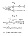
- FIG. 1 is a diagram showing the configuration of a single-antenna FM-CW radar.
- a modulating signal generator 1 applies a modulating signal to a voltage-controlled oscillator 2 for frequency modulation, and the frequency-modulated wave is passed through a circulator 5 and transmitted out from the antenna AT.
- the signal thus transmitted out and reflected from a target object, such as a vehicle traveling in front, is received by the antenna AT, and the received signal is input to a frequency converter 4 via the circulator 5.
- the input signal is mixed with a local signal separated by a directional coupler 3 from the output of the voltage-controlled oscillator 2, to produce a beat signal.
- FIG 2 is a diagram for explaining the principle of FM-CW radar when the relative velocity with respect to the target object is zero.
- the transmitted wave is a triangular wave whose frequency changes as shown by a solid line in part (a) of Figure 2.
- f 0 is the center frequency of the transmitted wave
- ⁇ f is the FM modulation amplitude
- Tm is the repetition period.
- the transmitted wave is reflected from the target object and received by the antenna; the received wave is shown by a dashed line in part (a) of Figure 2.
- the received wave is shifted in frequency from the transmitted signal (i.e., produces a beat) according to the distance between the radar and the target object.
- FIG. 3 is a diagram for explaining the principle of FM-CW radar when the relative velocity with respect to the target object is v.
- the frequency of the transmitted wave changes as shown by a solid line in part (a) of Figure 3.
- the transmitted wave is reflected from the target object and received by the antenna; the received wave is shown by a dashed line in part (a) of Figure 3.
- the received wave is shifted in frequency from the transmitted signal (i.e., produces a beat) according to the distance between the radar and the target object.
- the beat frequency component fb can be expressed by the following equation.
- the distance and the relative velocity with respect to the target object can be obtained from the above equation (1) or (2).
- a single-antenna time division control type FM-CW radar uses a single antenna as a transmitting/receiving antenna AT, which is switched between transmission and reception by time division control with a transmit-receive switching section comprising a switching means.
- the transmitting power may leak into the receiving system through the transmit-receive switching section. This can cause such problems as saturation gain compression of the receiving system, increased leakage of the transmit-receive switching frequency into the receiving system, and increased FM-AM conversion noise.
- the present invention provides a single-antenna time division control type FM-CW radar which comprises a transmitting/receiving antenna and a transmit-receive switching section and performs switching between transmission and reception by time division, wherein an amplifier is provided in each signal path in a transmitting system and a receiving system, including the transmit-receive switching section, and control means is provided for alternately causing the amplifier provided in the transmitting system and the amplifier provided in the receiving system to operate in synchronism with transmit and receive timings, thereby performing the switching between transmission and reception.
- the operation of the amplifiers is controlled by controlling the gain of each of the amplifiers.
- the amplifiers can be made to switch on and off.
- the amplifiers are connected in a multiple stage configuration, and the amplifiers connected in a multiple stage configuration are provided at a plurality of locations along each signal path in the transmitting system and the receiving system.
- a multiplier is provided in series with the amplifier in a local signal separator provided in the signal path of the transmitting system, and the multiplier may be switched on and off to perform the switching between transmission and reception in conjunction with the amplifier.
- a passive device can be used as the transmit-receive switching section, and a hybrid circuit or a Y-shaped power distributor can be used as the passive device.
- the single-antenna time division control type FM-CW radar of the present invention as an amplifier is provided in each signal path in the transmitting system and the receiving system, and as the transmitting and receiving systems are isolated from each other by turning the amplifiers on and off by varying the bias voltage applied to the amplifiers, reliable isolation can be provided between the transmitting and receiving systems. Furthermore, when the amplifiers are connected in multiple stages and provided at a plurality of locations along each signal path in the transmitting system and the receiving system, isolation between the transmitting and receiving systems becomes more reliable and easier to adjust.
- a passive device such as a hybrid circuit or a Y-shaped power distributor is used in the transmit-receive switching section, not only can the power consumption be reduced, but the need to use a switch in the transmit-receive switching section can be eliminated; as a result, there is no need to use ICs having different bias conditions, and the amount of bias circuitry can be reduced, achieving a cost reduction.
- FIG 4 is a diagram showing the configuration of a single-antenna time division control type FM-CW radar.
- a single antenna is used as a transmitting/receiving antenna AT, and a transmit-receive switching section 6 comprising a switching means switches the antenna between transmission and reception by time division control.
- a modulating signal generator 1 applies a modulating signal to a voltage-controlled oscillator 2 for frequency modulation, and the frequency-modulated output passes through the transmit-receive switching section 6 and is transmitted out from the antenna AT.
- Reference numeral 7 is a modulating signal generator which generates a modulating signal of frequency fsw for switching the transmit-receive switching section 6.
- the signal reflected from a target object such as a vehicle traveling in front is received by the transmitting/receiving antenna AT and input via the transmit-receive switching section 6; the input signal is mixed in the first frequency converter 4-1 with a local signal separated by a directional coupler 3 from the output of the voltage-controlled oscillator 2, to produce an IF signal.
- the signal output from the first frequency converter 4-1 is mixed in the second frequency converter 4-2 with the signal of frequency fsw generated by the modulating signal generator 7, and is thus downconverted to produce a beat signal which carries information on the distance and relative velocity of the target object.
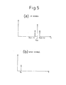
- FIG. 5 is a diagram showing one example of the frequency spectrum of the IF signal output from the first frequency converter 4-1 in the single-antenna time division control type FM-CW radar system of Figure 4, and one example of the frequency spectrum of the beat signal output from the second frequency converter 4-2.
- the frequency spectrum of the IF signal consists of the frequency fsw and its sideband frequencies fsw ⁇ fr.
- fsw is the switching frequency of the transmit-receive switching section 6
- fr is the frequency due to the distance (range) to the target object when the relative velocity is zero. The greater the distance to the target object, the farther the sideband frequencies are spaced away from fsw.
- This output signal is mixed in the second frequency converter 4-2 with the signal of frequency fsw and downconverted to a frequency equal to the difference between the frequencies fsw and fsw ⁇ fr, to extract the beat signal having the frequency spectrum fb shown in Figure 5(b).
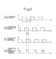
- Figure 6 is a diagram showing transmit and receive timings for the single-antenna time division control type FM-CW radar.
- a signal is transmitted out with the timing of period T as shown in part (a)
- the return timing of a reflected wave reflected from a target is as shown in part (b).
- the receive timing during which the reflected signal can be received is in the section that does not overlap with the transmit timing (a), as shown in part (c). Accordingly, the timing that the reflected signal can be received is during td, as shown in part (d).
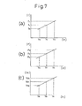
- FIG. 7 is a diagram showing graphs indicating relationships between the frequency, power, etc. and the voltage applied to the varactor diode or the gate.
- Figure 7(a) when the voltage V T applied to the varactor diode or the gate is varied from Vc to Va or Vb, the frequency varies from fc to fa or fb.
- Figure 7(b) is a graph indicating a relationship between the voltage V T and the power. Ideally, the power should remain unchanged, for example, at a constant value Pc. In actuality, however, the power varies from Pc to Pa or Pb.
- the voltage Vd generated due to AM detection in the frequency converter varies according to the power P, so that it also varies from Vdc to Vda or Vdb, as shown in Figure 7(c).
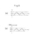
- Figure 8 is a diagram showing the waveform of the signal that the modulating signal generator applies to the voltage-controlled oscillator and the waveform of the voltage vd generated at that time.
- the signal that the modulating signal generator applies to the voltage-controlled oscillator is in the form of a triangular wave.
- the waveform of the voltage Vd becomes triangular as shown in Figure 8(b), and this causes PM-AM conversion noise.
- FIG 9 is a diagram illustrating one configuration example of the single-antenna time division control type FM-CW radar shown in Figure 4.
- the modulating signal generator 1 applies a modulating signal to the voltage-controlled oscillator 2 for frequency modulation, and the frequency-modulated signal is input to a local signal separator 8.
- the frequency-modulated wave is, for example, a signal in the 38 GHz band.
- the local signal separator 8 comprises a passive device such as a hybrid circuit H, amplifiers A1 and A2, and multipliers T1 and T2, and an output from the hybrid circuit H is passed through the amplifier A1 and multiplier T1 and supplied to amplifiers A3 and A4.
- the other output from the hybrid circuit H is passed through the amplifier A2 and multiplier T2 and supplied as a local signal to the frequency converter 4-1.
- Each output from the hybrid circuit H is multiplied by the multiplier T1 and T2 to 76 GHz, for example.
- the output of the amplifiers A3 and A4 is passed trough the transmit-receive switching section 6 and transmitted from the transmitting/receiving antenna AT.
- the modulated wave thus transmitted is reflected by a target object such as a vehicle traveling in front, and the reflected wave is received by the antenna AT and input to the frequency converter 4-1 through amplifiers A5/A6 and A7/A8.
- the input signal is mixed with the local signal output from the multiplier T2, to produce an IF signal.
- Vcc is the power supplied to the amplifiers.
- Indicated at 7 is the modulating signal generator which generates the modulating signal of frequency fsw for switching the transmit-receive switching section 6.
- the IF signal output from the frequency converter 4-1 is mixed in the frequency converter 4-2 with the signal of frequency fsw output from the modulating signal generator, and is thus downconverted to produce a beat signal which carries information on the distance and relative velocity of the target object.
- the configuration shown in Figure 9 has a problem that the transmitting power leaks into the receiving system through the transmit-receive switching section 6 because, as previously described, the timing is switched alternately between transmission and reception by the transmit-receive switching section 6.
- the present invention solves this problem.
- FIG 10 is a diagram showing the configuration of the single-antenna time division control type FM-CW radar according to the present invention.
- the transmit-receive switching section 6 comprises transmitting amplifiers A10, A11, and A12, a passive device such as a hybrid circuit H as a duplexer, and receiving amplifiers A20 and A21.
- the transmitting amplifiers A1, A3, A4, A10, A11, and A12 are supplied with a bias voltage VA and are thus put in the operating state, i.e., the ON state.
- the receiving amplifiers A20, A21, A5, A6, A7, and A8 are supplied with a bias voltage VB and are thus put in the non-operating state, i.e., the OFF state.
- the amplifier A2 is supplied with the normal supply voltage Vcc, and the frequency converter 4-1 is constantly supplied with a local output.
- the above bias voltages VA and VB are supplied to the transmitting side and receiving side alternately. For example, during transmission, the bias voltage VA is applied to the transmitting amplifiers so that the transmitting amplifiers are caused to operate, and during reception, the bias voltage VA is applied to the receiving amplifiers so that the receiving amplifiers are caused to operate.
- the receiving system is off, while during reception, the transmitting system is off, thus separating one from the other and preventing the transmitting power from leaking into the receiving system.
- the bias voltage need not necessarily be one that turns the amplifiers on and off, the only requirement being that the amplifiers be put in the operating or non-operating state sufficiently to prevent the transmitting power from leaking into the receiving system.
- Figure 11 is a diagram showing the configuration of each amplifier A.
- the signal is input at gate G and output at drain D.
- Figure 12 is a diagram showing graphs depicting how the gain of the amplifier A varies when the bias voltage to the gate G or the drain D is varied.
- Graph (a) shows how the gain varies when the bias voltage to the drain is varied from V B to V A while holding the gate voltage V C constant.
- Graph (b) shows how the gain varies when the bias voltage to the gate is varied from V B to V A while holding the drain voltage V D constant.
- the gain is low at G B .
- the amplifier A hardly operates and is essentially in the OFF state.
- the gain is high at G A , so that the amplifier A operates and is thus in the ON state.
- the on/off operation of the amplifier A can be controlled by varying the bias voltage applied to the gate or drain. Accordingly, in Figure 10, on transmission the bias voltage for the transmitting amplifiers is set to V A to put them in the ON state, while the bias voltage for the receiving amplifiers A is set to V B to put them in the OFF state. On reception, the state is reversed; the receiving system and the transmitting system can thus be isolated from each other.
- the amplifiers A1 and A2 in the local signal separator 8 are placed in front of the multipliers T1 and T2 so that the amplification is performed at low frequencies before the multiplication. This is because, at lower frequencies, the amplifiers are easier to manufacture and also easier to operate in an on/off fashion.
- a plurality of amplifiers are used and connected in a multiple stage configuration, but instead, only one amplifier may be used to serve the same purpose.
- isolation between the transmitting and receiving sides becomes more reliable and the adjustment easier than when only one amplifier is used.
- the transmitting and receiving systems can be isolated from each other more reliably by simultaneously turning the amplifiers on and off.
- switching between transmission and reception has been described as being performed using the amplifiers, but the switching between transmission and reception can also be performed on the transmitting side by turning on and off the multiplier T1 in the local signal separator 8 of Figure 10 in conjunction with the amplifiers.
- the configuration of the multiplier is the same as that of the amplifier shown in Figure 11. Its characteristics can also be depicted as shown in Figure 12. In Figure 12, however, the magnitude of the voltage plotted along the abscissa is different from that plotted for the amplifier, and further, the ordinate represents the frequency conversion gain whose magnitude is different from that of the gain plotted for the amplifier.
- the operation of the multiplier is substantially the same as that of the amplifier.
- a passive device such as a hybrid circuit or a Y-shaped power distributor can be used in the transmit-receive switching section connected to the antenna.
- An example of the hybrid circuit is shown in Figure 13, and an example of the Y-shaped power distributor is shown in Figure 14.
- the example shown in Figure 13 is a rat race type hybrid circuit.
- an MMIC switch such as shown in Figure 16 has been used to accomplish isolation between the transmitting and receiving sides by turning off the receiving side during transmission and turning on the receiving side when transmission is not performed.
- the hybrid circuit H cannot provide sufficient isolation between the transmitting and receiving sides, sufficient isolation can be provided between the transmitting and receiving sides, as when the switch is used, by combining the hybrid circuit H with amplifiers as shown in Figure 17 and by switching between transmission and reception by alternately turning the transmitting amplifier At and receiving amplifier Ar on and off. Accordingly, the hybrid circuit H can be used in the transmit-receive section. The same is true of the Y-shaped power distributor.
Landscapes
- Engineering & Computer Science (AREA)
- Radar, Positioning & Navigation (AREA)
- Remote Sensing (AREA)
- Computer Networks & Wireless Communication (AREA)
- Physics & Mathematics (AREA)
- General Physics & Mathematics (AREA)
- Signal Processing (AREA)
- Radar Systems Or Details Thereof (AREA)
Abstract
In a single-antenna time division control type FM-CW
radar, an amplifier is provided in each signal path in a
transmitting system and a receiving system, and the
amplifier provided in the transmitting system and the
amplifier provided in the receiving system are operated
alternately in synchronism with transmit and receive
timings, to perform switching between transmission and
reception. The operation of the amplifiers is controlled
by controlling the gain of each of the amplifiers. This
configuration provides enhanced isolation between the
transmitting and receiving systems, and prevents
transmitting power from leaking into the receiving system
through a transmit-receive switching section.
Description
The present invention relates to transmit-receive
switching in a single-antenna time division control type
FM-CW radar and, more particularly, to a means for
providing reliable isolation between transmitting and
receiving systems.
FM-CW radar is used as a radar system for measuring
distance and relative velocity with respect to a target
object. Since FM-CW radar can measure the distance and
the relative velocity of a vehicle traveling in front by
using a simple signal processing circuit, and as its
transmitter and receiver can be constructed with simple
circuitry, this type of radar is used as an automotive
collision avoidance radar.
The principle of FM-CW radar is as follows. An
oscillator is frequency-modulated, for example, by a
triangular wave of several hundred hertz, and the
frequency-modulated wave is transmitted; then, a
reflected signal from a target object is received, and
the received signal is frequency-demodulated using the
frequency-modulated wave as the local frequency. Here,
the reflected wave from the target is shifted in
frequency from the transmitted signal (i.e., produces a
beat) according to the distance between the radar and the
target and also to the Doppler shift due to the relative
velocity of the target. Accordingly, the distance and
the relative velocity of the target object can be
measured from this frequency shift.
In an FM-CW radar system, a triangular wave is often
used as the modulating signal, and the descrigtion given
herein deals with the case where a triangular wave is
used as the modulating signal, but it will be appreciated
that a modulating wave of other shape, such as a sawtooth
wave or a trapezoidal wave, can be used instead of the
triangular wave.
Figure 1 is a diagram showing the configuration of a
single-antenna FM-CW radar. As shown in Figure 1, a
modulating signal generator 1 applies a modulating signal
to a voltage-controlled oscillator 2 for frequency
modulation, and the frequency-modulated wave is passed
through a circulator 5 and transmitted out from the
antenna AT. The signal thus transmitted out and
reflected from a target object, such as a vehicle
traveling in front, is received by the antenna AT, and
the received signal is input to a frequency converter 4
via the circulator 5. In the frequency converter 4, the
input signal is mixed with a local signal separated by a
directional coupler 3 from the output of the voltage-controlled
oscillator 2, to produce a beat signal.
Figure 2 is a diagram for explaining the principle
of FM-CW radar when the relative velocity with respect to
the target object is zero. In this case, the transmitted
wave is a triangular wave whose frequency changes as
shown by a solid line in part (a) of Figure 2. In the
figure, f0 is the center frequency of the transmitted
wave, Δf is the FM modulation amplitude, and Tm is the
repetition period. The transmitted wave is reflected
from the target object and received by the antenna; the
received wave is shown by a dashed line in part (a) of
Figure 2. The round trip time of the radio wave to and
from the target object is given by T = 2r/C, where r is
the distance to the target object and C is the velocity
of propagation of the radio wave.
Here, the received wave is shifted in frequency from
the transmitted signal (i.e., produces a beat) according
to the distance between the radar and the target object.
The beat frequency component fb can be expressed by the
following equation.
fb = fr = (4·Δf/C·Tm)r
Figure 3, on the other hand, is a diagram for
explaining the principle of FM-CW radar when the relative
velocity with respect to the target object is v. The
frequency of the transmitted wave changes as shown by a
solid line in part (a) of Figure 3. The transmitted wave
is reflected from the target object and received by the
antenna; the received wave is shown by a dashed line in
part (a) of Figure 3. Here, the received wave is shifted
in frequency from the transmitted signal (i.e., produces
a beat) according to the distance between the radar and
the target object. In this case, since the relative
velocity with respect to the target object is v, a
Doppler shift occurs, and the beat frequency component fb
can be expressed by the following equation.
fb = fr ± fd = (4·Δf/C·Tm)r ± (2·f0 /C)v
The symbols in the above equations (1) and (2) have
the following meanings.
- fb:
- Transmit/receive beat frequency
- fr:
- Range (distance) frequency
- fd:
- Velocity frequency
- f0:
- Center frequency of transmitted wave
- Δf:
- Frequency modulation amplitude
- Tm:
- Period of modulated wave
- C:
- Velocity of light (velocity of radio wave)
- T:
- Round trip time of radio wave to and from target object
- r:
- Range (distance) to target object
- v:
- Relative velocity with respect to target object
Thus, the distance and the relative velocity with
respect to the target object can be obtained from the
above equation (1) or (2).
Here, consider the beat signal power; then, the
receiving power, Pr, of the antenna can be expressed by
Pr = {(G2 ·λ2 ·σ·Pt)/((4π)3 ·r4 )}·La
and the beat output power Pb by
Pb = Pr·Cmix
The symbols in the above equations (3) and (4) have
the following meanings.
- G:
- Antenna gain
- λ:
- wavelength
- σ:
- Reflecting object area
- Pt:
- Transmitting power
- r:
- Range to target object
- Cmix:
- Conversion loss in mixer
On the other hand, a single-antenna time division
control type FM-CW radar uses a single antenna as a
transmitting/receiving antenna AT, which is switched
between transmission and reception by time division
control with a transmit-receive switching section
comprising a switching means.
However, in the case of the single-antenna time
division control type FM-CW radar, since the timing is
switched alternately between transmission and reception,
the transmitting power may leak into the receiving system
through the transmit-receive switching section. This can
cause such problems as saturation gain compression of the
receiving system, increased leakage of the transmit-receive
switching frequency into the receiving system,
and increased FM-AM conversion noise.
Accordingly, it is an object of the present
invention to provide increased isolation between the
transmitting and receiving systems in a single-antenna
time division control type FM-CW radar and thereby
prevent the transmitting power from leaking into the
receiving system through the transmit-receive switching
section.
The present invention provides a single-antenna time
division control type FM-CW radar which comprises a
transmitting/receiving antenna and a transmit-receive
switching section and performs switching between
transmission and reception by time division, wherein an
amplifier is provided in each signal path in a
transmitting system and a receiving system, including the
transmit-receive switching section, and control means is
provided for alternately causing the amplifier provided
in the transmitting system and the amplifier provided in
the receiving system to operate in synchronism with
transmit and receive timings, thereby performing the
switching between transmission and reception.
The operation of the amplifiers is controlled by
controlling the gain of each of the amplifiers. The
amplifiers can be made to switch on and off.
The amplifiers are connected in a multiple stage
configuration, and the amplifiers connected in a multiple
stage configuration are provided at a plurality of
locations along each signal path in the transmitting
system and the receiving system.
A multiplier is provided in series with the
amplifier in a local signal separator provided in the
signal path of the transmitting system, and the
multiplier may be switched on and off to perform the
switching between transmission and reception in
conjunction with the amplifier.
A passive device can be used as the transmit-receive
switching section, and a hybrid circuit or a Y-shaped
power distributor can be used as the passive device.
In the single-antenna time division control type FM-CW
radar of the present invention, as an amplifier is
provided in each signal path in the transmitting system
and the receiving system, and as the transmitting and
receiving systems are isolated from each other by turning
the amplifiers on and off by varying the bias voltage
applied to the amplifiers, reliable isolation can be
provided between the transmitting and receiving systems.
Furthermore, when the amplifiers are connected in
multiple stages and provided at a plurality of locations
along each signal path in the transmitting system and the
receiving system, isolation between the transmitting and
receiving systems becomes more reliable and easier to
adjust.
Further, as a passive device such as a hybrid
circuit or a Y-shaped power distributor is used in the
transmit-receive switching section, not only can the
power consumption be reduced, but the need to use a
switch in the transmit-receive switching section can be
eliminated; as a result, there is no need to use ICs
having different bias conditions, and the amount of bias
circuitry can be reduced, achieving a cost reduction.
Furthermore, when a multiplier is used to perform
switching between transmission and reception, or when an
amplifier (A1, A2) is provided in front of the multiplier
and operated at a low frequency band, isolation between
the transmitting and receiving systems can be achieved
efficiently.
By providing the isolation between the transmitting
and receiving systems as described above, it becomes
possible to obtain a proper receiving gain, reduce FM-AM
conversion noise as well as the leakage of the switching
frequency to the beat signal, and improve the S/N ratio
of the receiver. This serves to improve the detection
performance of the radar.
The present invention will be described in further
detail below with reference to drawings.
Figure 4 is a diagram showing the configuration of a
single-antenna time division control type FM-CW radar.
As shown in Figure 4, a single antenna is used as a
transmitting/receiving antenna AT, and a transmit-receive
switching section 6 comprising a switching means switches
the antenna between transmission and reception by time
division control. At the receiving side are provided a
first frequency converter 4-1 and a second frequency
converter 4-2.
A modulating signal generator 1 applies a modulating
signal to a voltage-controlled oscillator 2 for frequency
modulation, and the frequency-modulated output passes
through the transmit-receive switching section 6 and is
transmitted out from the antenna AT. Reference numeral 7
is a modulating signal generator which generates a
modulating signal of frequency fsw for switching the
transmit-receive switching section 6.
The signal reflected from a target object such as a
vehicle traveling in front is received by the
transmitting/receiving antenna AT and input via the
transmit-receive switching section 6; the input signal is
mixed in the first frequency converter 4-1 with a local
signal separated by a directional coupler 3 from the
output of the voltage-controlled oscillator 2, to produce
an IF signal. The signal output from the first frequency
converter 4-1 is mixed in the second frequency converter
4-2 with the signal of frequency fsw generated by the
modulating signal generator 7, and is thus downconverted
to produce a beat signal which carries information on the
distance and relative velocity of the target object.
Figure 5 is a diagram showing one example of the
frequency spectrum of the IF signal output from the first
frequency converter 4-1 in the single-antenna time
division control type FM-CW radar system of Figure 4, and
one example of the frequency spectrum of the beat signal
output from the second frequency converter 4-2. As shown
in Figure 5(a), the frequency spectrum of the IF signal
consists of the frequency fsw and its sideband
frequencies fsw±fr. Here, fsw is the switching frequency
of the transmit-receive switching section 6, and fr is
the frequency due to the distance (range) to the target
object when the relative velocity is zero. The greater
the distance to the target object, the farther the
sideband frequencies are spaced away from fsw. This
output signal is mixed in the second frequency converter
4-2 with the signal of frequency fsw and downconverted to
a frequency equal to the difference between the
frequencies fsw and fsw±fr, to extract the beat signal
having the frequency spectrum fb shown in Figure 5(b).
Figure 6 is a diagram showing transmit and receive
timings for the single-antenna time division control type
FM-CW radar. When a signal is transmitted out with the
timing of period T as shown in part (a), the return
timing of a reflected wave reflected from a target is as
shown in part (b). However, the receive timing during
which the reflected signal can be received is in the
section that does not overlap with the transmit timing
(a), as shown in part (c). Accordingly, the timing that
the reflected signal can be received is during td, as
shown in part (d).
Next, an explanation will be given of how FM-AM
conversion noise increases. When applying a modulation
to a voltage-controlled oscillator that uses a varactor
diode or a voltage-controlled oscillator whose gate
voltage is varied, the frequency and power of the signal
output from the voltage-controlled oscillator vary
depending on the voltage applied to the varactor diode or
the gate. Figure 7 is a diagram showing graphs
indicating relationships between the frequency, power,
etc. and the voltage applied to the varactor diode or the
gate.
As shown in Figure 7(a), when the voltage VT applied
to the varactor diode or the gate is varied from Vc to Va
or Vb, the frequency varies from fc to fa or fb. Figure
7(b) is a graph indicating a relationship between the
voltage VT and the power. Ideally, the power should
remain unchanged, for example, at a constant value Pc.
In actuality, however, the power varies from Pc to Pa or
Pb.
On the other hand, the voltage Vd generated due to
AM detection in the frequency converter varies according
to the power P, so that it also varies from Vdc to Vda or
Vdb, as shown in Figure 7(c).
Figure 8 is a diagram showing the waveform of the
signal that the modulating signal generator applies to
the voltage-controlled oscillator and the waveform of the
voltage vd generated at that time. As shown in Figure
8(a), the signal that the modulating signal generator
applies to the voltage-controlled oscillator is in the
form of a triangular wave. When the signal voltage shown
in Figure 8(a) is applied to the voltage-controlled
oscillator, as the power P varies as shown in Figure
7(b), the waveform of the voltage Vd becomes triangular
as shown in Figure 8(b), and this causes PM-AM conversion
noise.
Figure 9 is a diagram illustrating one configuration
example of the single-antenna time division control type
FM-CW radar shown in Figure 4. The modulating signal
generator 1 applies a modulating signal to the voltage-controlled
oscillator 2 for frequency modulation, and the
frequency-modulated signal is input to a local signal
separator 8. The frequency-modulated wave is, for
example, a signal in the 38 GHz band. The local signal
separator 8 comprises a passive device such as a hybrid
circuit H, amplifiers A1 and A2, and multipliers T1 and
T2, and an output from the hybrid circuit H is passed
through the amplifier A1 and multiplier T1 and supplied
to amplifiers A3 and A4. The other output from the
hybrid circuit H is passed through the amplifier A2 and
multiplier T2 and supplied as a local signal to the
frequency converter 4-1. Each output from the hybrid
circuit H is multiplied by the multiplier T1 and T2 to 76
GHz, for example. The output of the amplifiers A3 and A4
is passed trough the transmit-receive switching section 6
and transmitted from the transmitting/receiving antenna
AT. The modulated wave thus transmitted is reflected by
a target object such as a vehicle traveling in front, and
the reflected wave is received by the antenna AT and
input to the frequency converter 4-1 through amplifiers
A5/A6 and A7/A8. The input signal is mixed with the
local signal output from the multiplier T2, to produce an
IF signal. In Figure 9, Vcc is the power supplied to the
amplifiers. Indicated at 7 is the modulating signal
generator which generates the modulating signal of
frequency fsw for switching the transmit-receive
switching section 6. The IF signal output from the
frequency converter 4-1 is mixed in the frequency
converter 4-2 with the signal of frequency fsw output
from the modulating signal generator, and is thus
downconverted to produce a beat signal which carries
information on the distance and relative velocity of the
target object.
The configuration shown in Figure 9 has a problem
that the transmitting power leaks into the receiving
system through the transmit-receive switching section 6
because, as previously described, the timing is switched
alternately between transmission and reception by the
transmit-receive switching section 6. The present
invention solves this problem.
Figure 10 is a diagram showing the configuration of
the single-antenna time division control type FM-CW radar
according to the present invention. The basic
configuration is the same as that shown in Figure 9, and
only differences from Figure 9 will be described below.
In Figure 10, the transmit-receive switching section 6
comprises transmitting amplifiers A10, A11, and A12, a
passive device such as a hybrid circuit H as a duplexer,
and receiving amplifiers A20 and A21. In the condition
shown, the transmitting amplifiers A1, A3, A4, A10, A11,
and A12 are supplied with a bias voltage VA and are thus
put in the operating state, i.e., the ON state. On the
other hand, the receiving amplifiers A20, A21, A5, A6,
A7, and A8 are supplied with a bias voltage VB and are
thus put in the non-operating state, i.e., the OFF state.
The amplifier A2 is supplied with the normal supply
voltage Vcc, and the frequency converter 4-1 is
constantly supplied with a local output. The above bias
voltages VA and VB are supplied to the transmitting side
and receiving side alternately. For example, during
transmission, the bias voltage VA is applied to the
transmitting amplifiers so that the transmitting
amplifiers are caused to operate, and during reception,
the bias voltage VA is applied to the receiving
amplifiers so that the receiving amplifiers are caused to
operate. Therefore, during transmission, the receiving
system is off, while during reception, the transmitting
system is off, thus separating one from the other and
preventing the transmitting power from leaking into the
receiving system. In this case, however, the bias
voltage need not necessarily be one that turns the
amplifiers on and off, the only requirement being that
the amplifiers be put in the operating or non-operating
state sufficiently to prevent the transmitting power from
leaking into the receiving system.
Figure 11 is a diagram showing the configuration of
each amplifier A. The signal is input at gate G and
output at drain D. Figure 12 is a diagram showing graphs
depicting how the gain of the amplifier A varies when the
bias voltage to the gate G or the drain D is varied.
Graph (a) shows how the gain varies when the bias voltage
to the drain is varied from VB to VA while holding the
gate voltage VC constant. When the bias voltage VB is
applied, the gain is low at GB. At this time, the
amplifier A hardly operates and is essentially in the OFF
state. On the other hand, when the bias voltage VA is
applied, the amplifier A operates and is thus in the ON
state.
Graph (b) shows how the gain varies when the bias
voltage to the gate is varied from VB to VA while holding
the drain voltage VD constant. When the bias voltage VB
is applied, the gain is low at GB. At this time, the
amplifier A hardly operates and is essentially in the OFF
state. On the other hand, when the bias voltage VA is
applied, the gain is high at GA, so that the amplifier A
operates and is thus in the ON state.
As described above, the on/off operation of the
amplifier A can be controlled by varying the bias voltage
applied to the gate or drain. Accordingly, in Figure 10,
on transmission the bias voltage for the transmitting
amplifiers is set to VA to put them in the ON state,
while the bias voltage for the receiving amplifiers A is
set to VB to put them in the OFF state. On reception,
the state is reversed; the receiving system and the
transmitting system can thus be isolated from each other.
In the configuration shown in Figure 10, the
amplifiers A1 and A2 in the local signal separator 8 are
placed in front of the multipliers T1 and T2 so that the
amplification is performed at low frequencies before the
multiplication. This is because, at lower frequencies,
the amplifiers are easier to manufacture and also easier
to operate in an on/off fashion.
Further, in the configuration shown in Figure 10, a
plurality of amplifiers are used and connected in a
multiple stage configuration, but instead, only one
amplifier may be used to serve the same purpose.
However, when a plurality of amplifiers are connected in
a multiple stage configuration, isolation between the
transmitting and receiving sides becomes more reliable
and the adjustment easier than when only one amplifier is
used. Furthermore, as the amplifiers are provided at a
plurality of locations in both the transmitting and
receiving systems, the transmitting and receiving systems
can be isolated from each other more reliably by
simultaneously turning the amplifiers on and off.
In the above embodiment, switching between
transmission and reception has been described as being
performed using the amplifiers, but the switching between
transmission and reception can also be performed on the
transmitting side by turning on and off the multiplier T1
in the local signal separator 8 of Figure 10 in
conjunction with the amplifiers. The configuration of
the multiplier is the same as that of the amplifier shown
in Figure 11. Its characteristics can also be depicted
as shown in Figure 12. In Figure 12, however, the
magnitude of the voltage plotted along the abscissa is
different from that plotted for the amplifier, and
further, the ordinate represents the frequency conversion
gain whose magnitude is different from that of the gain
plotted for the amplifier. The operation of the
multiplier is substantially the same as that of the
amplifier.
Further, a passive device such as a hybrid circuit
or a Y-shaped power distributor can be used in the
transmit-receive switching section connected to the
antenna. An example of the hybrid circuit is shown in
Figure 13, and an example of the Y-shaped power
distributor is shown in Figure 14. The example shown in
Figure 13 is a rat race type hybrid circuit. when the
hybrid circuit H is used, for example, leakage occurs as
shown by a dashed line in Figure 15, and sufficient
isolation cannot be provided between the transmitting and
receiving sides. Therefore, in the conventional art, an
MMIC switch such as shown in Figure 16 has been used to
accomplish isolation between the transmitting and
receiving sides by turning off the receiving side during
transmission and turning on the receiving side when
transmission is not performed.
However, if the hybrid circuit H cannot provide
sufficient isolation between the transmitting and
receiving sides, sufficient isolation can be provided
between the transmitting and receiving sides, as when the
switch is used, by combining the hybrid circuit H with
amplifiers as shown in Figure 17 and by switching between
transmission and reception by alternately turning the
transmitting amplifier At and receiving amplifier Ar on
and off. Accordingly, the hybrid circuit H can be used
in the transmit-receive section. The same is true of the
Y-shaped power distributor.
Claims (8)
- A single-antenna time division control type FM-CW radar which comprises a transmitting/receiving antenna and a transmit-receive switching section and performs switching between transmission and reception by time division, wherein an amplifier is provided in each signal path in a transmitting system and a receiving system, including the transmit-receive switching section, and control means is provided for causing the amplifier provided in the transmitting system and the amplifier provided in the receiving system to operate in synchronism with transmit and receive timings, and wherein the switching between transmission and reception is performed by alternately operating the amplifiers.
- A single-antenna time division control type FM-CW radar as claimed in claim 1, wherein the operation of the amplifiers is controlled by controlling the gain of each of the amplifiers.
- A single-antenna time division control type FM-CW radar as claimed in claim 1, wherein the operation of the amplifiers is an on/off operation.
- A single-antenna time division control type FM-CW radar as claimed in claim 1, wherein the amplifiers are connected in a multiple stage configuration.
- A single-antenna time division control type FM-CW radar as claimed in claim 1, wherein the amplifiers are provided at a plurality of locations along each signal path in the transmitting system and the receiving system.
- A single-antenna time division control type FM-CW radar as claimed in claim 1, wherein a multiplier provided in series with the amplifier in a local signal separator provided in the signal path of the transmitting system is operated on and off to perform the switching between transmission and reception in conjunction with the amplifier.
- A single-antenna time division control type FM-CW radar as claimed in claim 1, wherein a passive device is connected as the transmit-receive switching section to the antenna.
- A single-antenna time division control type FM-CW radar as claimed in claim 7, wherein the passive device is a hybrid circuit or a Y-shaped power distributor.
Applications Claiming Priority (3)
| Application Number | Priority Date | Filing Date | Title |
|---|---|---|---|
| JP2000312173 | 2000-10-12 | ||
| JP2000312173A JP2002122661A (en) | 2000-10-12 | 2000-10-12 | Fm-cw radar of 1 antenna time sharing control system |
| PCT/JP2001/009013 WO2002031531A1 (en) | 2000-10-12 | 2001-10-12 | One-antenna time-division control fm-cw radar |
Publications (2)
| Publication Number | Publication Date |
|---|---|
| EP1326086A1 true EP1326086A1 (en) | 2003-07-09 |
| EP1326086A4 EP1326086A4 (en) | 2004-08-25 |
Family
ID=18791816
Family Applications (1)
| Application Number | Title | Priority Date | Filing Date |
|---|---|---|---|
| EP01974840A Withdrawn EP1326086A4 (en) | 2000-10-12 | 2001-10-12 | One-antenna time-division control fm-cw radar |
Country Status (6)
| Country | Link |
|---|---|
| US (1) | US6720912B2 (en) |
| EP (1) | EP1326086A4 (en) |
| JP (1) | JP2002122661A (en) |
| KR (1) | KR20020062320A (en) |
| CN (1) | CN1261771C (en) |
| WO (1) | WO2002031531A1 (en) |
Cited By (1)
| Publication number | Priority date | Publication date | Assignee | Title |
|---|---|---|---|---|
| CN103439706A (en) * | 2013-08-09 | 2013-12-11 | 安徽白鹭电子科技有限公司 | Single-channel time division radar transceiver system |
Families Citing this family (16)
| Publication number | Priority date | Publication date | Assignee | Title |
|---|---|---|---|---|
| JP4204358B2 (en) | 2003-03-20 | 2009-01-07 | 富士通テン株式会社 | Transmission / reception shared FM-CW radar apparatus and signal processing method thereof |
| JP4111853B2 (en) | 2003-03-25 | 2008-07-02 | 富士通テン株式会社 | FM-CW radar device for shared transmission and reception and signal processing method for FM-CW radar |
| JP2007049212A (en) * | 2003-11-05 | 2007-02-22 | Murata Mfg Co Ltd | Variable reactance apparatus, oscillator, and radar apparatus |
| JP4278507B2 (en) * | 2003-12-26 | 2009-06-17 | 富士通テン株式会社 | FM-CW radar equipment |
| JP2006010329A (en) | 2004-06-22 | 2006-01-12 | Fujitsu Ten Ltd | Timing adjustment method for radar and radar with automatic timing adjustment function |
| CN1906500B (en) * | 2004-10-14 | 2010-09-29 | 安立股份有限公司 | Small-size low-power-consumption short-range radar and control method thereof |
| US20090028074A1 (en) * | 2005-06-22 | 2009-01-29 | Knox Michael E | Antenna feed network for full duplex communication |
| US8111640B2 (en) | 2005-06-22 | 2012-02-07 | Knox Michael E | Antenna feed network for full duplex communication |
| US9780437B2 (en) | 2005-06-22 | 2017-10-03 | Michael E. Knox | Antenna feed network for full duplex communication |
| US7791530B2 (en) * | 2006-01-05 | 2010-09-07 | Autoliv Asp, Inc. | Time duplex apparatus and method for radar sensor front-ends |
| WO2008082638A1 (en) * | 2006-12-29 | 2008-07-10 | Knox Michael E | High isolation signal routing assembly for full duplex communication |
| US8750173B2 (en) | 2006-12-29 | 2014-06-10 | Mode-1 Corporation | High isolation signal routing assembly for full duplex communication |
| FR2937813B1 (en) * | 2008-10-28 | 2010-12-03 | Thales Sa | METHOD FOR RECONSTITUTING A VARIABLE INTERVALLOUS CUT SIGNAL AND TRANSPONDER USING THE METHOD |
| DE102011054242B3 (en) | 2011-10-06 | 2012-11-22 | Technische Universität Berlin | Circuit arrangement for a front end of an FMCW radar transceiver, FMCW radar transceiver and method of operation |
| JP5963573B2 (en) * | 2012-06-29 | 2016-08-03 | 古野電気株式会社 | Radar equipment |
| CN109752714B (en) * | 2018-12-29 | 2023-07-14 | 内蒙古工业大学 | A rotating radar micro-variation monitoring data processing method and radar system |
Family Cites Families (14)
| Publication number | Priority date | Publication date | Assignee | Title |
|---|---|---|---|---|
| JPS63147043A (en) | 1986-12-10 | 1988-06-20 | ナショナル住宅産業株式会社 | Method for assembling small roof |
| JPS63147043U (en) * | 1987-03-18 | 1988-09-28 | ||
| JPH058480A (en) | 1991-07-03 | 1993-01-19 | Oki Electric Ind Co Ltd | Passbook identification device |
| JPH0511079A (en) | 1991-07-08 | 1993-01-19 | Hitachi Ltd | Metal port |
| JPH058480U (en) * | 1991-07-18 | 1993-02-05 | 三菱電機株式会社 | Radar receiver |
| JPH0511079U (en) * | 1991-07-24 | 1993-02-12 | 三菱電機株式会社 | Radar receiver |
| DE4203932A1 (en) * | 1992-02-11 | 1993-08-12 | Deutsche Aerospace | SEND / RECEIVE MODULE |
| JP3106088B2 (en) | 1995-05-26 | 2000-11-06 | 三菱電機株式会社 | Radar transponder |
| JP3347571B2 (en) | 1996-03-12 | 2002-11-20 | 富士通株式会社 | Radar equipment |
| US5745076A (en) * | 1996-09-05 | 1998-04-28 | Northrop Grumman Corporation | Transmit/receive module for planar active apertures |
| JP3061261B2 (en) * | 1997-04-01 | 2000-07-10 | 本田技研工業株式会社 | FM radar equipment |
| JPH11352219A (en) | 1998-06-05 | 1999-12-24 | Mitsubishi Electric Corp | Automotive radar equipment |
| JP4046425B2 (en) | 1998-11-11 | 2008-02-13 | 富士通テン株式会社 | Millimeter wave radar gain control apparatus and method, and radar apparatus |
| JP3600499B2 (en) * | 2000-03-17 | 2004-12-15 | 三菱電機株式会社 | FM pulse Doppler radar device |
-
2000
- 2000-10-12 JP JP2000312173A patent/JP2002122661A/en active Pending
-
2001
- 2001-10-12 WO PCT/JP2001/009013 patent/WO2002031531A1/en not_active Ceased
- 2001-10-12 KR KR1020027007178A patent/KR20020062320A/en not_active Ceased
- 2001-10-12 EP EP01974840A patent/EP1326086A4/en not_active Withdrawn
- 2001-10-12 CN CNB018030319A patent/CN1261771C/en not_active Expired - Fee Related
- 2001-10-12 US US10/149,482 patent/US6720912B2/en not_active Expired - Fee Related
Cited By (1)
| Publication number | Priority date | Publication date | Assignee | Title |
|---|---|---|---|---|
| CN103439706A (en) * | 2013-08-09 | 2013-12-11 | 安徽白鹭电子科技有限公司 | Single-channel time division radar transceiver system |
Also Published As
| Publication number | Publication date |
|---|---|
| WO2002031531A1 (en) | 2002-04-18 |
| KR20020062320A (en) | 2002-07-25 |
| US6720912B2 (en) | 2004-04-13 |
| CN1261771C (en) | 2006-06-28 |
| EP1326086A4 (en) | 2004-08-25 |
| US20020180635A1 (en) | 2002-12-05 |
| CN1392958A (en) | 2003-01-22 |
| JP2002122661A (en) | 2002-04-26 |
Similar Documents
| Publication | Publication Date | Title |
|---|---|---|
| US6720912B2 (en) | Single-antenna time division control type FM-CW radar | |
| JP2981312B2 (en) | FM-CW radar device | |
| EP1757953B1 (en) | FM-CW radar system | |
| US10094920B2 (en) | Range resolution in FMCW radars | |
| EP1326089B1 (en) | Radar apparatus | |
| US6087980A (en) | Radar of FM-CW system | |
| US7714772B2 (en) | Transmit-receive FM-CW radar apparatus | |
| EP0825455A2 (en) | Failure determination device of radar apparatus | |
| US6972711B2 (en) | Transmit-receive FM-CW radar apparatus | |
| US7443336B2 (en) | In-vehicle pulse radar device | |
| JP3524231B2 (en) | FM-CW radar apparatus and noise component determination method in FM-CW radar method | |
| JP2004245647A (en) | Short-range radar device and vehicle equipped with short-range radar device | |
| Mondal et al. | 77 GHz MMIC T/R module for diplex radar application in collision avoidance radar (CAR) | |
| JP2000056012A (en) | Range finder | |
| JP2008191090A (en) | Radar equipment | |
| JP2008191089A (en) | Radar equipment |
Legal Events
| Date | Code | Title | Description |
|---|---|---|---|
| PUAI | Public reference made under article 153(3) epc to a published international application that has entered the european phase |
Free format text: ORIGINAL CODE: 0009012 |
|
| 17P | Request for examination filed |
Effective date: 20020610 |
|
| AK | Designated contracting states |
Designated state(s): AT BE CH CY DE DK ES FI FR GB GR IE IT LI LU MC NL PT SE TR |
|
| AX | Request for extension of the european patent |
Extension state: AL LT LV MK RO SI |
|
| RBV | Designated contracting states (corrected) |
Designated state(s): AT BE CH DE FR GB LI |
|
| A4 | Supplementary search report drawn up and despatched |
Effective date: 20040715 |
|
| 17Q | First examination report despatched |
Effective date: 20070820 |
|
| STAA | Information on the status of an ep patent application or granted ep patent |
Free format text: STATUS: THE APPLICATION IS DEEMED TO BE WITHDRAWN |
|
| 18D | Application deemed to be withdrawn |
Effective date: 20080103 |