EP1325832A2 - Drive train member having convex splines - Google Patents
Drive train member having convex splines Download PDFInfo
- Publication number
- EP1325832A2 EP1325832A2 EP02258840A EP02258840A EP1325832A2 EP 1325832 A2 EP1325832 A2 EP 1325832A2 EP 02258840 A EP02258840 A EP 02258840A EP 02258840 A EP02258840 A EP 02258840A EP 1325832 A2 EP1325832 A2 EP 1325832A2
- Authority
- EP
- European Patent Office
- Prior art keywords
- drive train
- driveshaft
- splines
- train assembly
- splined
- Prior art date
- Legal status (The legal status is an assumption and is not a legal conclusion. Google has not performed a legal analysis and makes no representation as to the accuracy of the status listed.)
- Withdrawn
Links
Images


Classifications
-
- F—MECHANICAL ENGINEERING; LIGHTING; HEATING; WEAPONS; BLASTING
- F16—ENGINEERING ELEMENTS AND UNITS; GENERAL MEASURES FOR PRODUCING AND MAINTAINING EFFECTIVE FUNCTIONING OF MACHINES OR INSTALLATIONS; THERMAL INSULATION IN GENERAL
- F16D—COUPLINGS FOR TRANSMITTING ROTATION; CLUTCHES; BRAKES
- F16D3/00—Yielding couplings, i.e. with means permitting movement between the connected parts during the drive
- F16D3/16—Universal joints in which flexibility is produced by means of pivots or sliding or rolling connecting parts
- F16D3/18—Universal joints in which flexibility is produced by means of pivots or sliding or rolling connecting parts the coupling parts (1) having slidably-interengaging teeth
- F16D3/185—Universal joints in which flexibility is produced by means of pivots or sliding or rolling connecting parts the coupling parts (1) having slidably-interengaging teeth radial teeth connecting concentric inner and outer coupling parts
Definitions
- This invention relates in general to vehicle drive train assemblies for transferring rotational power, such as from an engine to an axle assembly of the vehicle.
- this invention relates to a drive train member such as a driveshaft having convex splines.
- a drive train assembly for transmitting rotational power from an engine/transmission assembly to one or more wheels of the vehicle.
- a typical drive train assembly includes a tubular driveshaft which is connected between an output shaft of the transmission and an input shaft of a rear axle assembly to rotatably drive the rear wheels.
- a typical drive train assembly includes right and left halfshafts which are connected between a transaxle assembly and the right and left wheels, respectively.
- a typical drive train assembly includes a transfer case which rotatably supports an input shaft for receiving rotational power from the engine/transmission assembly, as well as front and rear output shafts for transferring rotational power from the input shaft to the front and rear wheels of the vehicle, respectively.
- a front auxiliary driveshaft is connected between the front output shaft of the transfer case and an input shaft of a front axle assembly to rotatably drive the front wheels
- a rear driveshaft is connected between the rear output shaft of the transfer case and an input shaft of the rear axle assembly to rotatably drive the rear wheels.
- the transfer case is spaced apart from the transmission
- a front driveshaft is connected between the output shaft of the transmission and the input shaft of the transfer case.
- the different shafts are usually connected together by the use of universal joints.
- a first universal joint is usually connected between the front output shaft of the transfer case and a first end of the front auxiliary driveshaft
- a second universal joint is connected between a second end of the front auxiliary driveshaft and the input shaft of the front axle assembly.
- the universal joints provide a rotational driving connection from the front output shaft of the transfer case through the front auxiliary driveshaft to the input shaft of the front axle assembly, while accommodating a limited amount of angular misalignment between the rotational axes of these three shafts.
- the use of universal joints to connect both ends of a driveshaft increases the complexity and cost of the drive train assembly.
- This invention relates to a vehicle drive train assembly which includes a source of rotational power and at least one rotatably driven vehicle wheel.
- a male splined member and a female splined member are connected between the source of rotational power and the vehicle wheel to transmit rotational power therebetween.
- At least one of the splined members is a driveshaft.
- the splines of the male splined member have side surfaces and outer surfaces which are convex in shape.
- the convex splines of the male splined member cooperate with the splines of the female splined member to connect the splined members together in a manner that allows for limited angular and axial movement therebetween.
- the angular movement is caused at least in part by up or down movement of the vehicle wheel during operation of the vehicle.
- the invention in another embodiment, relates to a vehicle drive train assembly which includes a source of rotational power and at least one rotatably driven vehicle wheel.
- a male splined driveshaft and a female splined member are connected between the source of rotational power and the vehicle wheel to transmit rotational power therebetween.
- the driveshaft includes a main tubular portion, a male splined end portion, and a neck portion therebetween.
- the neck portion has a diameter which is less than the diameters of both the male splined end portion and the main tubular portion.
- the splines of the male splined member have side surfaces and outer surfaces which are convex in shape.
- the convex splines of the male splined member cooperate with the splines of the female splined member to connect the splined members together in a manner that allows for limited angular and axial movement therebetween.
- the invention in a further embodiment, relates to a vehicle drive train assembly which includes a source of rotational power and at least one rotatably driven vehicle wheel.
- a male splined member and a female splined member are connected between the source of rotational power and the vehicle wheel to transmit rotational power therebetween.
- At least one of the splined members is a driveshaft which is located completely outside of the source of rotational power.
- the splines of the male splined member have side surfaces and outer surfaces which are convex in shape.
- the convex splines of the male splined member cooperate with the splines of the female splined member to connect the splined members together in a manner that allows for limited angular and axial movement therebetween.
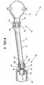
- FIG. 1 there is illustrated in Fig. 1 several members of a vehicle drive train assembly, indicated generally at 10.
- the illustrated drive train members are part of the drive train assembly of a four-wheel drive vehicle.
- the invention can also be used on front-rear drive vehicles, rear wheel drive vehicles, or other types of vehicles in which a drive train assembly is provided for transmitting rotational power from a source of rotational power to at least one rotatably driven vehicle wheel.
- the drive train assembly includes a front auxiliary driveshaft 12.
- the driveshaft 12 typically includes a main tubular portion 14 which is in the shape of an elongated cylindrical tube having a generally continuous cross-section.
- the shape and size of the driveshaft 12 are typical of propeller shafts, although other shapes and sizes of driveshafts could also be used depending on the particular drive train assembly.
- the driveshaft 12 is connected to an input shaft 16 of a front axle assembly 18.
- the front axle assembly 18 is conventional in the art.
- the driveshaft 12 is connected to the front axle assembly 18 by the use of a universal joint, indicated generally at 20.
- the universal joint 20 is conventional in the art and includes a yoke portion 22 of the driveshaft 12 which is attached to one end of the main tubular portion 14, such as by a weld.
- the universal joint 20 also includes a second yoke portion 24 which is attached to the input shaft 16 of the front axle assembly 18.
- a cross 26 is mounted between the two yoke portions 22 and 24.
- the universal joint 20 provides a rotational driving connection between the driveshaft 12 and the input shaft 16 of the front axle assembly 18 while accommodating a limited amount of angular misalignment between their rotational axes.
- the driveshaft 12 is also connected to a front output shaft 28 of a transfer case 30.
- a front auxiliary driveshaft would be connected between a transfer case and a front axle assembly by the use of universal joints at both ends of the driveshaft.
- the drive train assembly of this invention includes a connecting structure, indicated generally at 32, which is used in place of a universal joint at one end of the driveshaft 12.
- the connecting structure 32 includes a male splined member, the driveshaft 12 in the embodiment shown, and a female splined member, the front output shaft 28 of the transfer case 30 in the embodiment shown.
- the front output shaft 28 could be the male splined member while the driveshaft 12 is the female splined member.
- At least one of the splined members is a driveshaft which is usually located completely outside of the source of rotational power of the drive train assembly.
- the connecting structure 32 could be used to replace the universal joint 20 between the driveshaft 12 and the front axle assembly 18.
- the driveshaft 12 includes a male splined end portion 34, and a neck portion 36 between the male splined end portion 34 and the main tubular portion 14 of the driveshaft 12.
- the neck portion 36 has a diameter which is less than the diameters of both the male splined end portion 34 and the main tubular portion 14.
- the preferred driveshaft 12 includes an end piece 38 which is attached to the main tubular portion 14 of the driveshaft 12.
- the end piece 38 includes the male splined end portion 34 and a tube seat portion 40 which is attached to the main tubular portion 14.
- the end piece 38 also includes the neck portion 36 which has a diameter less than the diameters of both the male splined end portion 34 and the tube seat portion 40.
- the male splined end portion 34 has a diameter which is smaller than the diameter of the tube seat portion 40.
- the end piece 38 can be attached to the main tubular portion 34 of the driveshaft 12 by any suitable method.
- a conventional welding technique can be used to permanently join the driveshaft parts together.
- conventional welding techniques involve the application of heat to localized areas of two metallic members, which results in a coalescence of the two metallic members. Such welding may or may not be performed with the application of pressure, and may or may not include the use of a filler metal.
- the tube seat portion 40 has a diameter which is slightly more or less than the diameter of the main tubular portion 14, so that the end piece 38 and the main tubular portion 34 overlap in a tight fit.
- the end piece 38 is attached to the main tubular portion 34 of the driveshaft 12 by a magnetically impelled arc butt (MIAB) welding method.
- MIAB magnetically impelled arc butt
- the tube seat portion 40 of the end piece 38 has the same diameter as the main tubular portion 14.
- the tube seat portion 40 and the main tubular portion 14 are forced together while applying a DC welding current.
- the end piece 38 and the main tubular portion 14 are then moved apart to a distance of 1-3 millimeters in order to strike an arc.
- This arc is rotated at high speed around the circumference of the weld interface using a static radial magnetic field which can be generated using permanent magnets or electromagnets.
- Arc rotation is sustained for a few seconds until the ends of the tube seat portion 40 and the main tubular portion 14 are heated to a high temperature or are molten.
- the tube seat portion 40 and the main tubular portion 14 are then brought rapidly together under a predetermined pressure and the arc is extinguished.
- the molten metal at the weld interface is expelled and a solid phase weld results from sustained pressure, which consolidates the joint.
- the end piece 38 is made from a case hardened steel, preferably a high-strength grade of steel with a wear-resistant surface.
- the material could also be a lesser grade steel with a surface treatment to strengthen the surface.
- the male splined end portion 34 of the driveshaft 12 is made from a material which is different from the material used to make the main tubular portion 14.
- the material used to make the male splined end portion 34 may be stronger and/or more wear-resistant than the main tubular portion 14 to better withstand the stresses at the splined connection.
- the male splined end portion is formed as a ring having splines on its outer circumferential surface, and the ring is attached to the main tubular portion by any suitable method, such as by welding.
- a seal 42 is provided to cover the connecting structure 32 between the driveshaft 12 and the front output shaft 28 of the transfer case 30, in order to prevent the entry of dirt, water and other contaminants into the connecting structure 32.
- the seal 42 also allows a limited amount of angular and axial movement between the driveshaft 12 and the front output shaft 28. Any suitable structure and attachment of the seal 42 can be used for this purpose.
- the seal 42 is a flexible boot type seal which is attached at its ends with a pair of clamps 44 to the tube seat portion 40 of the end piece 38 and to the outer circumferential surface of the front output shaft 28.
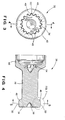
- the male splined end portion 34 of the driveshaft 12 has a plurality of outwardly extending longitudinal splines 46 formed on its outer circumferential surface.
- the splines 46 each have a pair of side surfaces 48 on opposing sides of the spline 46, and a radially outer surface 50.
- the side surfaces 48 and the outer surfaces 50 of the splines 46 are convex in shape.
- the convex shape of the splines 46 is best illustrated in Figs. 6 and 7.
- the spline 46 has a pair of side surfaces 48 on opposing sides of the spline 46.
- the side surfaces 48 are both convex in shape.
- the side surfaces 48 are arcuate or crowned in shape, each forming a smoothly curving arc.
- the spline 46 is generally elliptical in shape.
- the arcuate side surfaces 48 each have a radius R1.
- the spline 46 has a radially outer surface 50.
- the outer surface 50 is convex in shape.
- the outer surface 50 is arcuate or crowned in shape, forming a smoothly curving arc.
- the arcuate outer surface 50 has a radius R2.
- the convex splines 46 of the invention contrast with the straight splines used in a slip yoke assembly of a typical drive train assembly.
- the front output shaft 28 of the transfer case 30 has a plurality of inwardly extending splines 52 formed on its inner surface.
- the outwardly extending splines 46 of the driveshaft 12 cooperate with the inwardly extending splines 52 of the front output shaft 28 to connect the driveshaft 12 to the front output shaft 28 in a manner that allows for limited axial movement therebetween.
- the convex shape of the splines 46 of the driveshaft 12 allows for limited angular movement between the driveshaft 12 and the front output shaft 28. This feature of the invention allows the connecting structure 32 to be used in place of a universal joint in a vehicle drive train assembly.
- a slip yoke assembly of a typical drive train assembly does not allow angular movement between the connected drive train members.
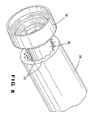
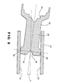
- Figs. 1, 8 and 9 illustrate the angular connection between the end piece 38 of the driveshaft 12 and the front output shaft 28 of the transfer case 30, allowed by the convex splines 46 of the invention.
- the end piece 38 and the front output shaft 28 are connected at a joint angle A (the angle between the longitudinal axis L1 of the end piece 38 and the longitudinal axis L2 of the front output shaft 28).
- the convex splines 46 are shaped to allow a joint angle of at least about 3°, more preferably at least about 5°, and typically between about 3° and about 7°. It has been determined that the radius R1 (Fig.
- each of the convex side surfaces 48 of the spline 46 is the most important structural feature for allowing a desired joint angle.
- the optimum radius R1 will differ depending on the particular drive train assembly.
- the radius R2 (Fig. 7) of the convex outer surface 50 of the spline 46 also affects the amount of joint angle allowed. In general, the smaller the radius R2, the larger can be the joint angle.
- the optimum radius R2 will differ depending on the particular drive train assembly.
- the reduced diameter neck portion 36 of the end piece 38 is also important for allowing the angular connection between the end piece 38 of the driveshaft 12 and the front output shaft 28 of the transfer case 30.
- the neck portion 36 provides clearance for the end of the output shaft 28 to extend inwardly toward the side of the end piece 38 when the two members are angled relative to each other.
- a sufficient angular connection can be achieved without the use of a reduced diameter neck portion 36.
- the male splined end portion 34 of the end piece 38 could be formed with a larger diameter, and/or the male splined end portion 34 could be connected closer to the outer end of the front output shaft 28.
- any suitable method can be used to manufacture the end piece 38 including the male splined end portion 34 having the convex splines 46, the neck portion 36 and the tube seat portion 40.
- the end piece 38 is manufactured using a forming operation, such as a forging operation or a rolling operation.
- a hot metal blank is forged into the rough shape of the end piece 38.
- a recess having a hexagonal outer portion and a conical inner portion is formed in one end of the blank, and a conical recess is formed in the other end of the blank.
- Figs. 2 and 4 show a hexagonal recess 54 and a conical recess 56 formed in the opposing ends of the end piece 38.
- the formed piece is mounted on a lathe; the recesses 54 and 56 enable the lathe to hold and center the formed piece.
- the lathe has a rotatable drive member having a hexagonal end portion, which extends into the hexagonal recess 54 to drive the formed piece to rotate.
- the lathe machines the outer surface of the formed piece to produce its final shape except for the convex splines.
- an automated turning center would typically be used for machining instead of a lathe.
- a net forming process could be used instead of the forging process followed by the machining process.
- the convex splines 46 are created by a machining process which uses a suitable tool, such as a gear hobbing, to cut the splines into the desired shape.
- the splines could be created by a forming operation such as roll forming.
Landscapes
- Engineering & Computer Science (AREA)
- General Engineering & Computer Science (AREA)
- Mechanical Engineering (AREA)
- Shafts, Cranks, Connecting Bars, And Related Bearings (AREA)
- Motor Power Transmission Devices (AREA)
Abstract
Description
Claims (10)
- A vehicle drive train assembly comprising:a source of rotational power;at least one rotatably driven vehicle wheel; anda male splined member and a female splined member which are connected between the source of rotational power and the at least one vehicle wheel to transmit rotational power therebetween, wherein at least one of the splined members is a driveshaft, the splines of the male splined member having side surfaces which are convex in shape and outer surfaces which are convex in shape, the convex splines of the male splined member cooperating with the splines of the female splined member to connect the splined members together in a manner that allows for limited angular and axial movement therebetween, wherein the angular movement is caused at least in part by up or down movement of the at least one vehicle wheel during operation of the vehicle.
- The drive train assembly defined in Claim 1 wherein the convex splines are shaped to allow a joint angle between the male splined member and the female splined member of at least about 3°.
- The drive train assembly defined in Claim 1 wherein the convex splines are generally elliptical in shape.
- The drive train assembly defined in Claim 1 wherein the male splined member is the driveshaft, and wherein the convex splines are located on an end portion of the driveshaft.
- The drive train assembly defined in Claim 4 wherein the driveshaft includes an end piece and a main tubular portion, the end piece including the male splined end portion, a tube seat portion which is attached to the main tubular portion, and a neck portion between the male splined end portion and the tube seat portion, the neck portion having a diameter which is less than the diameters of both the male splined end portion and the tube seat portion.
- The drive train assembly defined in Claim 5 wherein the male splined end portion is made from a material which is different from the material used to make the neck portion and the tube seat portion.
- The drive train assembly defined in Claim 5 wherein the male splined end portion has a diameter which is smaller than the diameter of the tube seat portion.
- The drive train assembly defined in Claim 5 wherein the tube seat portion is hollow.
- The drive train assembly defined in Claim 1 further comprising a seal which covers the connection between the male splined member and the female splined member.
- The drive train assembly defined in Claim 1 further comprising a rotatably driven front axle and a rotatably driven rear axle, the at least one vehicle wheel including front and rear vehicle wheels mounted on the front and rear axles, respectively, and further comprising a transfer case which transmits rotational power from the source of rotational power to the front and rear axles, wherein a first one of the splined members is the driveshaft which is connected between the transfer case and the front axle, and a second one of the splined members is provided on either the transfer case or the front axle.
Applications Claiming Priority (2)
| Application Number | Priority Date | Filing Date | Title |
|---|---|---|---|
| US36076 | 2001-12-27 | ||
| US10/036,076 US6871719B2 (en) | 2001-12-27 | 2001-12-27 | Drive train member having convex splines |
Publications (2)
| Publication Number | Publication Date |
|---|---|
| EP1325832A2 true EP1325832A2 (en) | 2003-07-09 |
| EP1325832A3 EP1325832A3 (en) | 2006-01-25 |
Family
ID=21886481
Family Applications (1)
| Application Number | Title | Priority Date | Filing Date |
|---|---|---|---|
| EP02258840A Withdrawn EP1325832A3 (en) | 2001-12-27 | 2002-12-20 | Drive train member having convex splines |
Country Status (4)
| Country | Link |
|---|---|
| US (1) | US6871719B2 (en) |
| EP (1) | EP1325832A3 (en) |
| BR (1) | BR0205424A (en) |
| MX (1) | MXPA02012951A (en) |
Cited By (4)
| Publication number | Priority date | Publication date | Assignee | Title |
|---|---|---|---|---|
| EP2440809A4 (en) * | 2009-06-10 | 2013-01-23 | Magna Powertrain America Inc | Low-angle spline coupling for power transmission units |
| EP2481880A3 (en) * | 2011-01-31 | 2015-11-18 | Precision Energy Services, Inc. | Drive shaft constant velocity joint assembly with radial elliptical projections |
| CN108019436A (en) * | 2017-12-14 | 2018-05-11 | 上海纳铁福传动系统有限公司 | spline universal joint |
| CN109563884A (en) * | 2017-06-29 | 2019-04-02 | 川崎重工业株式会社 | Rail truck gear shape flexure shaft coupling and the railcar bogie for having gear shape flexure shaft coupling |
Families Citing this family (6)
| Publication number | Priority date | Publication date | Assignee | Title |
|---|---|---|---|---|
| JP4313014B2 (en) * | 2002-09-30 | 2009-08-12 | 株式会社ジェイテクト | Shaft and manufacturing method thereof |
| CA2428484A1 (en) * | 2003-05-08 | 2004-11-08 | Gino Jobin | Tandem wheel assembly, mobile silvicultural apparatus including the same, and method for operating the apparatus |
| KR20070052741A (en) * | 2004-08-19 | 2007-05-22 | 루크 라멜렌 운트 쿠플룽스바우베타일리궁스 카게 | Conical pulley flexible drive transmission, a method of manufacturing the drive transmission and a vehicle having the drive transmission |
| USD710770S1 (en) * | 2012-11-15 | 2014-08-12 | Scott B. Caskey | Driver chassis |
| CN105517896B (en) | 2013-09-05 | 2018-04-13 | 空中客车营运有限公司 | Landing gear drive system flexible joint |
| CA2921136A1 (en) * | 2013-09-05 | 2015-03-12 | Airbus Operations Limited | Landing gear drive system flexible interface |
Family Cites Families (17)
| Publication number | Priority date | Publication date | Assignee | Title |
|---|---|---|---|---|
| US3292390A (en) * | 1965-04-01 | 1966-12-20 | Wildhaber Ernest | Gear coupling |
| US3698524A (en) | 1971-02-19 | 1972-10-17 | Int Harvester Co | I.p.t.o brake unit |
| US3892300A (en) | 1973-08-22 | 1975-07-01 | Gen Electric | Motorized wheel brake system |
| US3953158A (en) * | 1974-11-19 | 1976-04-27 | Eaton Corporation | Axial retention of drive shaft in a fluid pressure device |
| US4289213A (en) * | 1979-12-21 | 1981-09-15 | Borg-Warner Corporation | Angular output transfer case |
| US4388838A (en) | 1980-07-03 | 1983-06-21 | Eaton Corporation | Multiple countershaft simple transmission |
| US4493387A (en) * | 1982-08-12 | 1985-01-15 | Ford Motor Company | Clutch driven front axle fourwheel drive system |
| US4493404A (en) | 1982-11-22 | 1985-01-15 | Eaton Corporation | Hydraulic gerotor motor and parking brake for use therein |
| US4597476A (en) | 1983-04-04 | 1986-07-01 | Eaton Corporation | Hydraulic gerotor motor and parking brake for use therein |
| US4969371A (en) * | 1989-01-26 | 1990-11-13 | Renold, Inc. | Gear type flexible coupling |
| US5558174A (en) | 1994-01-26 | 1996-09-24 | Schaeff, Incorporated | Drive train assembly |
| US5647802A (en) | 1994-06-02 | 1997-07-15 | Torvec, Inc. | Variable-angle gears |
| US5725453A (en) * | 1995-08-17 | 1998-03-10 | New Venture Gear, Inc. | On-demand double offset transfer case |
| US5911286A (en) * | 1997-06-12 | 1999-06-15 | Gkn Automotive Inc | Independent suspension and halfshaft assembly with double crown spline joint |
| US6123518A (en) | 1998-03-13 | 2000-09-26 | Mi-Jack Products, Inc. | Integral shaft coupling for a flexible driveplate in a pump drivetrain |
| US6319132B1 (en) * | 1998-05-01 | 2001-11-20 | Dana Corporation | Motor vehicle torque transfer case with integral constant velocity (CV) joint |
| US6155395A (en) * | 1999-04-16 | 2000-12-05 | Borgwarner Inc. | Transfer case having parallel clutches |
-
2001
- 2001-12-27 US US10/036,076 patent/US6871719B2/en not_active Expired - Fee Related
-
2002
- 2002-12-19 MX MXPA02012951A patent/MXPA02012951A/en unknown
- 2002-12-20 EP EP02258840A patent/EP1325832A3/en not_active Withdrawn
- 2002-12-20 BR BR0205424-8A patent/BR0205424A/en not_active Application Discontinuation
Cited By (6)
| Publication number | Priority date | Publication date | Assignee | Title |
|---|---|---|---|---|
| EP2440809A4 (en) * | 2009-06-10 | 2013-01-23 | Magna Powertrain America Inc | Low-angle spline coupling for power transmission units |
| EP2481880A3 (en) * | 2011-01-31 | 2015-11-18 | Precision Energy Services, Inc. | Drive shaft constant velocity joint assembly with radial elliptical projections |
| CN109563884A (en) * | 2017-06-29 | 2019-04-02 | 川崎重工业株式会社 | Rail truck gear shape flexure shaft coupling and the railcar bogie for having gear shape flexure shaft coupling |
| EP3460278A4 (en) * | 2017-06-29 | 2020-03-18 | Kawasaki Jukogyo Kabushiki Kaisha | GEAR-TYPE FLEXIBLE SHAFT COUPLING FOR RAIL VEHICLE, AND RAIL VEHICLE BOGIE PROVIDED WITH SAME |
| US11008024B2 (en) | 2017-06-29 | 2021-05-18 | Kawasaki Jukogyo Kabushiki Kaisha | Railcar flexible gear coupling and railcar bogie including same |
| CN108019436A (en) * | 2017-12-14 | 2018-05-11 | 上海纳铁福传动系统有限公司 | spline universal joint |
Also Published As
| Publication number | Publication date |
|---|---|
| US6871719B2 (en) | 2005-03-29 |
| BR0205424A (en) | 2004-09-28 |
| MXPA02012951A (en) | 2003-09-22 |
| EP1325832A3 (en) | 2006-01-25 |
| US20030125116A1 (en) | 2003-07-03 |
Similar Documents
| Publication | Publication Date | Title |
|---|---|---|
| KR100854783B1 (en) | Two piece axle shaft | |
| EP3576901B1 (en) | A vehicle spindle and a method of attaching the spindle to a portion of an axle housing with alignement of the spindle with respect to the axle housing | |
| US6871719B2 (en) | Drive train member having convex splines | |
| EP4056295B1 (en) | Method of making an interaxle differential unit | |
| US6855061B2 (en) | Vehicular driveshaft assembly | |
| US7896749B2 (en) | Direct torque flow connection with optimized ratios in attachment methods | |
| JP6104598B2 (en) | Method for manufacturing outer joint member of constant velocity universal joint | |
| US10920831B2 (en) | Propshaft assembly having yoke friction welded to propshaft tube | |
| CN108603580B (en) | Differential assembly with two-piece carrier and welded ring gear | |
| AU2005209581B2 (en) | Method of manufacturing a splined member for use in a driveshaft assembly | |
| US7181846B2 (en) | Method of manufacturing a combined driveshaft tube and yoke assembly | |
| US7419433B2 (en) | ATV drive shaft and constant velocity joint | |
| JP2001225653A (en) | Aluminum propeller shaft provided with constant velocity joint | |
| CA2589117A1 (en) | A universal joint assembly for an automotive driveline system | |
| EP1493510A1 (en) | Method of manufacturing a combined driveshaft tube and yoke assembly | |
| JPH08270670A (en) | Manufacture of pipe yoke for drive-line-assembly | |
| US20050137022A1 (en) | Apparatus and method for friction welded tripod interconnecting shaft | |
| CN106460945A (en) | Manufacturing method for constant velocity universal joint outer joint member and outer joint member | |
| US20200108715A1 (en) | Propeller shaft yoke with improved tool clearance | |
| JPS60226302A (en) | Drive shaft for light vehicle | |
| JP2001082499A (en) | Constant velocity universal joint |
Legal Events
| Date | Code | Title | Description |
|---|---|---|---|
| PUAI | Public reference made under article 153(3) epc to a published international application that has entered the european phase |
Free format text: ORIGINAL CODE: 0009012 |
|
| AK | Designated contracting states |
Designated state(s): AT BE BG CH CY CZ DE DK EE ES FI FR GB GR IE IT LI LU MC NL PT SE SI SK TR |
|
| AX | Request for extension of the european patent |
Extension state: AL LT LV MK RO |
|
| PUAL | Search report despatched |
Free format text: ORIGINAL CODE: 0009013 |
|
| AK | Designated contracting states |
Kind code of ref document: A3 Designated state(s): AT BE BG CH CY CZ DE DK EE ES FI FR GB GR IE IT LI LU MC NL PT SE SI SK TR |
|
| AX | Request for extension of the european patent |
Extension state: AL LT LV MK RO |
|
| AKX | Designation fees paid | ||
| REG | Reference to a national code |
Ref country code: DE Ref legal event code: 8566 |
|
| STAA | Information on the status of an ep patent application or granted ep patent |
Free format text: STATUS: THE APPLICATION IS DEEMED TO BE WITHDRAWN |
|
| 18D | Application deemed to be withdrawn |
Effective date: 20060701 |