EP1325801B1 - Apparatus for making moulded plastics articles - Google Patents
Apparatus for making moulded plastics articles Download PDFInfo
- Publication number
- EP1325801B1 EP1325801B1 EP03250085A EP03250085A EP1325801B1 EP 1325801 B1 EP1325801 B1 EP 1325801B1 EP 03250085 A EP03250085 A EP 03250085A EP 03250085 A EP03250085 A EP 03250085A EP 1325801 B1 EP1325801 B1 EP 1325801B1
- Authority
- EP
- European Patent Office
- Prior art keywords
- reservoirs
- mould
- compartment
- dispensing
- mixing
- Prior art date
- Legal status (The legal status is an assumption and is not a legal conclusion. Google has not performed a legal analysis and makes no representation as to the accuracy of the status listed.)
- Expired - Lifetime
Links
- 239000002991 molded plastic Substances 0.000 title 1
- 239000000463 material Substances 0.000 claims abstract description 30
- 229920001169 thermoplastic Polymers 0.000 claims abstract description 7
- 239000004416 thermosoftening plastic Substances 0.000 claims abstract description 7
- 238000000465 moulding Methods 0.000 claims abstract description 6
- 238000002844 melting Methods 0.000 claims abstract description 5
- 230000008018 melting Effects 0.000 claims abstract description 5
- 229920001971 elastomer Polymers 0.000 claims abstract description 4
- 229920000642 polymer Polymers 0.000 claims abstract description 4
- 239000005060 rubber Substances 0.000 claims abstract description 4
- 239000004033 plastic Substances 0.000 claims description 21
- 229920003023 plastic Polymers 0.000 claims description 21
- 238000010438 heat treatment Methods 0.000 claims description 13
- 229910052751 metal Inorganic materials 0.000 claims description 8
- 239000002184 metal Substances 0.000 claims description 8
- 229920003225 polyurethane elastomer Polymers 0.000 claims description 3
- 229910052710 silicon Inorganic materials 0.000 claims description 3
- 239000010703 silicon Substances 0.000 claims description 3
- 229920002379 silicone rubber Polymers 0.000 claims description 3
- 230000003068 static effect Effects 0.000 claims description 3
- 230000001360 synchronised effect Effects 0.000 claims description 2
- 239000000543 intermediate Substances 0.000 abstract description 14
- 238000000034 method Methods 0.000 abstract 1
- 230000007246 mechanism Effects 0.000 description 19
- 238000005266 casting Methods 0.000 description 5
- IJGRMHOSHXDMSA-UHFFFAOYSA-N Atomic nitrogen Chemical compound N#N IJGRMHOSHXDMSA-UHFFFAOYSA-N 0.000 description 4
- 239000012190 activator Substances 0.000 description 4
- 239000003054 catalyst Substances 0.000 description 4
- 239000007789 gas Substances 0.000 description 3
- XKRFYHLGVUSROY-UHFFFAOYSA-N Argon Chemical compound [Ar] XKRFYHLGVUSROY-UHFFFAOYSA-N 0.000 description 2
- 239000004952 Polyamide Substances 0.000 description 2
- XUIMIQQOPSSXEZ-UHFFFAOYSA-N Silicon Chemical compound [Si] XUIMIQQOPSSXEZ-UHFFFAOYSA-N 0.000 description 2
- 238000010586 diagram Methods 0.000 description 2
- QSHDDOUJBYECFT-UHFFFAOYSA-N mercury Chemical compound [Hg] QSHDDOUJBYECFT-UHFFFAOYSA-N 0.000 description 2
- 229910052753 mercury Inorganic materials 0.000 description 2
- 229910052757 nitrogen Inorganic materials 0.000 description 2
- 229920002647 polyamide Polymers 0.000 description 2
- 239000007787 solid Substances 0.000 description 2
- 239000004593 Epoxy Substances 0.000 description 1
- 229920002430 Fibre-reinforced plastic Polymers 0.000 description 1
- 239000004677 Nylon Substances 0.000 description 1
- 239000002390 adhesive tape Substances 0.000 description 1
- 239000003570 air Substances 0.000 description 1
- 239000004411 aluminium Substances 0.000 description 1
- 229910052782 aluminium Inorganic materials 0.000 description 1
- XAGFODPZIPBFFR-UHFFFAOYSA-N aluminium Chemical compound [Al] XAGFODPZIPBFFR-UHFFFAOYSA-N 0.000 description 1
- 239000012080 ambient air Substances 0.000 description 1
- 229910052786 argon Inorganic materials 0.000 description 1
- 230000006835 compression Effects 0.000 description 1
- 238000007906 compression Methods 0.000 description 1
- 238000010276 construction Methods 0.000 description 1
- 230000001419 dependent effect Effects 0.000 description 1
- 230000000694 effects Effects 0.000 description 1
- 229920006351 engineering plastic Polymers 0.000 description 1
- 239000011151 fibre-reinforced plastic Substances 0.000 description 1
- 239000012765 fibrous filler Substances 0.000 description 1
- 239000002657 fibrous material Substances 0.000 description 1
- 239000000945 filler Substances 0.000 description 1
- 239000012530 fluid Substances 0.000 description 1
- 239000003365 glass fiber Substances 0.000 description 1
- 239000011261 inert gas Substances 0.000 description 1
- 239000007788 liquid Substances 0.000 description 1
- 238000003754 machining Methods 0.000 description 1
- 238000004519 manufacturing process Methods 0.000 description 1
- 239000000203 mixture Substances 0.000 description 1
- 238000010068 moulding (rubber) Methods 0.000 description 1
- 229920001778 nylon Polymers 0.000 description 1
- 239000007790 solid phase Substances 0.000 description 1
- 125000006850 spacer group Chemical group 0.000 description 1
- 229910001220 stainless steel Inorganic materials 0.000 description 1
- 239000010935 stainless steel Substances 0.000 description 1
- 239000012815 thermoplastic material Substances 0.000 description 1
Images



Classifications
-
- B—PERFORMING OPERATIONS; TRANSPORTING
- B29—WORKING OF PLASTICS; WORKING OF SUBSTANCES IN A PLASTIC STATE IN GENERAL
- B29C—SHAPING OR JOINING OF PLASTICS; SHAPING OF MATERIAL IN A PLASTIC STATE, NOT OTHERWISE PROVIDED FOR; AFTER-TREATMENT OF THE SHAPED PRODUCTS, e.g. REPAIRING
- B29C31/00—Handling, e.g. feeding of the material to be shaped, storage of plastics material before moulding; Automation, i.e. automated handling lines in plastics processing plants, e.g. using manipulators or robots
- B29C31/04—Feeding of the material to be moulded, e.g. into a mould cavity
-
- B—PERFORMING OPERATIONS; TRANSPORTING
- B29—WORKING OF PLASTICS; WORKING OF SUBSTANCES IN A PLASTIC STATE IN GENERAL
- B29C—SHAPING OR JOINING OF PLASTICS; SHAPING OF MATERIAL IN A PLASTIC STATE, NOT OTHERWISE PROVIDED FOR; AFTER-TREATMENT OF THE SHAPED PRODUCTS, e.g. REPAIRING
- B29C2791/00—Shaping characteristics in general
- B29C2791/004—Shaping under special conditions
- B29C2791/006—Using vacuum
-
- B—PERFORMING OPERATIONS; TRANSPORTING
- B29—WORKING OF PLASTICS; WORKING OF SUBSTANCES IN A PLASTIC STATE IN GENERAL
- B29C—SHAPING OR JOINING OF PLASTICS; SHAPING OF MATERIAL IN A PLASTIC STATE, NOT OTHERWISE PROVIDED FOR; AFTER-TREATMENT OF THE SHAPED PRODUCTS, e.g. REPAIRING
- B29C33/00—Moulds or cores; Details thereof or accessories therefor
- B29C33/38—Moulds or cores; Details thereof or accessories therefor characterised by the material or the manufacturing process
- B29C33/40—Plastics, e.g. foam or rubber
- B29C33/405—Elastomers, e.g. rubber
-
- B—PERFORMING OPERATIONS; TRANSPORTING
- B29—WORKING OF PLASTICS; WORKING OF SUBSTANCES IN A PLASTIC STATE IN GENERAL
- B29C—SHAPING OR JOINING OF PLASTICS; SHAPING OF MATERIAL IN A PLASTIC STATE, NOT OTHERWISE PROVIDED FOR; AFTER-TREATMENT OF THE SHAPED PRODUCTS, e.g. REPAIRING
- B29C39/00—Shaping by casting, i.e. introducing the moulding material into a mould or between confining surfaces without significant moulding pressure; Apparatus therefor
- B29C39/22—Component parts, details or accessories; Auxiliary operations
- B29C39/24—Feeding the material into the mould
-
- B—PERFORMING OPERATIONS; TRANSPORTING
- B29—WORKING OF PLASTICS; WORKING OF SUBSTANCES IN A PLASTIC STATE IN GENERAL
- B29C—SHAPING OR JOINING OF PLASTICS; SHAPING OF MATERIAL IN A PLASTIC STATE, NOT OTHERWISE PROVIDED FOR; AFTER-TREATMENT OF THE SHAPED PRODUCTS, e.g. REPAIRING
- B29C39/00—Shaping by casting, i.e. introducing the moulding material into a mould or between confining surfaces without significant moulding pressure; Apparatus therefor
- B29C39/22—Component parts, details or accessories; Auxiliary operations
- B29C39/42—Casting under special conditions, e.g. vacuum
-
- B—PERFORMING OPERATIONS; TRANSPORTING
- B29—WORKING OF PLASTICS; WORKING OF SUBSTANCES IN A PLASTIC STATE IN GENERAL
- B29K—INDEXING SCHEME ASSOCIATED WITH SUBCLASSES B29B, B29C OR B29D, RELATING TO MOULDING MATERIALS OR TO MATERIALS FOR MOULDS, REINFORCEMENTS, FILLERS OR PREFORMED PARTS, e.g. INSERTS
- B29K2105/00—Condition, form or state of moulded material or of the material to be shaped
- B29K2105/0002—Condition, form or state of moulded material or of the material to be shaped monomers or prepolymers
Definitions
- This invention relates to the moulding of plastics material articles, more particularly but not exclusively in the context of making one off or small quantities of articles, such as prototypes for testing designs later to be mass produced.
- Some plastics materials particularly some polymers including polyamide, e.g. nylon, are not easily moulded with fine detail, except with complex and expensive control equipment. This may be inappropriate for the kind of prototype manufacturing apparatus mentioned. Accordingly, an object of the invention is to provide apparatus for moulding which can produce a good result in the context but which is relatively inexpensive.
- US-A-5 529 212 and US-A-3 773 300 disclose apparatuses for moulding of plastics material articles according to the preamble of claim 1.
- EP-A-1 166 989 discloses a device having two pressurized chambers for vacuum casting plastic parts.
- apparatus for making a moulded thermoplastics material article, the apparatus comprising a plurality of reservoirs for receiving respective polymer thermoplastics intermediate components, heating means for melting said components in said reservoirs and maintaining them heated; mixing means for mixing the molten contents of the respective reservoirs; piston and cylinder means for transferring the reservoir contents out of the reservoirs, support means for supporting a rigid or soft rubber moulding; and dispensing means for dispensing said plastics material into a rigid or soft rubber mould supported by said support means; characterised in that said apparatus comprises:
- the vacuum pump and control means are operable for maintaining the ambient pressure in each of the two compartments less than atmospheric pressure.
- the mould is a silicon or polyurethane rubber mould.
- said dispensing means comprises mixing means, for example a static mixing tube, operable for mixing said plastics material before dispensing it to said mould.
- mixing means for example a static mixing tube, operable for mixing said plastics material before dispensing it to said mould.
- the apparatus comprises apparatus wherein said reservoirs and said cylinders are formed in respective metal blocks, said heating means being coupled to said blocks for heating the blocks.
- the Figure 1 equipment comprises a cabinet 1 divided into four compartments 2, 3, 4 and 5.
- the compartments 2 and 4 lie above respective ones of the compartments 3 and 5.
- the compartments 2, 3 and 4 have doors 6 (shown open) while compartment 5, which contains electro-mechanical control items and electronic control and computing apparatus (not shown), has a front panel supporting an emergency cut-off button 7 and a touch screen control panel 8.
- the compartment 5 contains electrical machinery including a vacuum pump 9 while the compartment 2 contains a mechanism 10 for mixing and dispensing plastics material intermediates.
- the compartments 2 and 3 are divided one from another by a sturdy floor plate 11 strong enough for the two compartments to remain sealed one from the other despite a substantial difference in vacuum within the two.
- the plate 11 could be made of aluminium or other suitable material.
- a valve 100 with a motor drive 101 is mounted in the plate 11 to permit the pressure in compartments 2 and 3 to be equalised or maintained equal when required.
- the intermediates comprise thermoplastic materials with or without fillers.
- the intermediates are chosen to give the desired mechanical properties of the material of the cast component, i.e. the hardness or Durometer reading and related properties such as tensile modulus, resilience, plasticity, compression resistance and elasticity.
- the intermediates might comprise commercially available materials such as Caprolactum along with the appropriate activators and catalysts. These components are intended to produce a polyamide plastics material with particular, mechanical properties, namely a relatively rigid material.
- the activator and catalyst might be replaced by an alternative catalyst and activator in specific proportions to give different properties, for example a relatively tougher plastics material.
- fibrous material or filler e.g. glass fibre, may be added to give a fibre reinforced plastics material cast component.
- the mechanism 10 comprises two closable reservoirs 20 and 21 each with a lid 22.
- a gas-tight bearing 23 is provided in the lid 22 of each reservoir to receive a shaft 24 carrying, inside the reservoir, a mixer paddle 25. Outside the respective reservoir, each shaft 24 is coupled to a respective electric motor 26.
- the lids of the reservoirs also have openings 27 into which there can be mounted respective funnels 28 (one is shown in the opening 27 of reservoir 21) or respective screwed plugs 29 (one is shown in the opening 27 of reservoir 22).
- the funnels 28 are fitted to enable the reservoirs to be filled with the required amounts of the chosen intermediates.
- the funnels 28 are then removed and replaced with the screwed plugs 29 to seal the reservoirs.
- the reservoirs are connected via respective gas taps 30 mounted in the lids 22 and flexible tubing 31 to a supply 32 of inert gas such as nitrogen or argon for forming a gas blanket over the contents of the reservoirs when the mechanism is in use.
- inert gas such as nitrogen or argon
- a heater here illustrated as two electrical resistance heating elements 33 and 34, coupled to a source of electrical power 35 and located beneath respective ones of the reservoirs 20 and 21, is provided for heating the reservoirs with a view to melting the plastics material intermediates to be mixed.
- the mechanism 10 also comprises two cylinders 36 and 37 containing respective pistons 38 and 39.
- the pistons 38 and 39 are connected via respective piston rods 40 and 41 to an electrically motorised drive mechanism 42.
- the mechanism 42 could be replaced by two separate mechanisms one for each cylinder. In either case, the cylinders 36 and 37 could be alongside one another rather than coaxially opposed.
- Each of the cylinders 36 and 37 is coupled via two conduits 43 and 44 and a valve 45 to a port 46 in the floor of the corresponding one of the two reservoirs 20 and 21.
- Each cylinder is also coupled via conduit 47 and a valve 48 to one of two conduits 49, one for each cylinder.
- the conduits 49 terminate near each other at an exit fitment 51.
- Heater elements 33 and 34 are preferably arranged or additional elements are provided, so as to maintain and regulate the temperature, not only of the reservoirs, but also the valves 45 and 48, the conduits 43, 44, 47 and 49, and the cylinders 36 and 37 so as to ensure the molten plastics materials are kept at the right temperature.
- the two reservoirs 20 and 21 are opened and, using the funnels 28, the appropriate intermediates are inserted. With the closure plugs 29 fitted and the gas blankets applied, the intermediates are then raised to the appropriate temperature, melting them if they are in the solid phase, and mixed by energising the mixer paddle drive motors 26. The mixed molten components are then drawn via valves 45 and conduits 43 and 44 into the cylinders 36 and 37 by appropriate movement of pistons 38 and 39 and subsequently expelled by the pistons 38 and 39 through valves 48 and conduits 47 and 49 out to the exit fitment 51.
- the two valves 45 are coupled to respective drive units 54 while the two valves 48 are coupled to respective drive units 58.
- the drive units 54 and 58 are operated in conjunction with the drive 42 coupled to the pistons 38 and 39 to move the contents of the reservoirs 20 and 21 to the cylinders 36 and 37 and then to the conduits 49 as appropriate.
- the valves may be operable so that, if the mixer tube is blocked say, the contents of the cylinders are transferred back to the reservoirs 20 and 21.
- the conduits 49 extend at specific angles to the vertical (60° for example) and the exit ends to the conduits are at a specific distance one from another so that the contents of the reservoirs exit from the conduits 49 as respective streams which impinge together and become mixed.
- a static mixing tube 52 i.e. a tube incorporating angled baffles 53, can be coupled to the fitment 51.
- the tube 52 leads down to a mould 60 positioned in the compartment 3 below the mechanism 10.
- a plain plastics tube (not shown) may be used to conduct the molten plastics material down to the mould 60 or the impinging streams exiting from the conduits 49 and 50 may be lead into a funnel 61 (illustrated in dashed lines to show that it is alternative to the tube 52) which leads down to the mould 60.
- This also enables the connection of widely differing mould sizes and geometries and gating points to the material outlet.
- the reservoirs 20 and 21 may be formed as through bores in a solid metal block 62, the block 62 being clamped by bolts (not shown) to the top of another solid metal block 63.
- the lids 22 and motors 26 are not shown in Figures 3 and 4.
- a lid 22 is shown fitted over the top of reservoir 21 while reservoir 20 is shown open.
- the motors 26 and paddles 25 are also not shown in this figure.
- the bottoms of the through bores are closed by block 63 with respective gaskets 64 therebetween.
- Respective side-by-side horizontal bores are provided in block 63 to form the cylinders 36 and 37.
- the pistons 38 and 39 may be elongate so as to extend back through the cylinders 36 and 37 to where they are coupled to the motor drive 42 (not shown in Figures 3 to 5).
- the motor drive 42 is operable to move the pistons by different distances dependent upon the quantities of the intermediates in the two reservoirs and to be mixed. This is done by providing a motor drive with respective motors 50 coupled via a suitable drive mechanism to the two pistons or by a single motor with a differential drive mechanism.
- the drive mechanism can comprise a ball-screw drive and the or each motor can comprise a stepper motor.
- the valves 45 and 48 are provided with the conduits 43, 44, 47 and 49 in a further block of metal 70 bolted to the end face of block 63 so as to cover the forward ends of the cylinders 36 and 37, a gasket 71 being provided between the block 70 and each cylinder.
- the drive units 54 and 58 are mounted above the valves 45 and 48, for example, by being fixed via a metal spacer 73 to block 62.
- the drive units 54 and 58 are coupled to respective cylindrical valve members 74 of the valves 45 and 48 by valve rods 75, preferably with a degree of flexibility in the rods to take up any misalignment of the valve members 74 in the valve seats 76.
- the heating elements 33 and 34 can be embodied as stainless steel heating cartridges (not shown) located in bores in the various blocks 62 and/or 63.
- the object of providing the reservoirs, cylinders, conduits and valves in relatively massive, bolted together blocks of metal is to achieve even temperature and less differential expansion of the parts of the mechanism.
- the mould 60 is located in compartment 3 supported on a hydraulic or manual or electric lifting platform 80.
- the mould 60 is a silicon rubber mould, for example the kind of mould which is made by embedding a prototype of an article to be moulded, or an existing item to be copied in liquid silicon mould making material in a mould box and allowing the material to set.
- the mould is then cut, for example, by hand using a sharp knife, to divide the mould in two parts so that the prototype or original item can be removed.
- the two parts of the mould are then placed together and secured, for example, by wrapping adhesive tape around them.
- a mould entry aperture and overflow apertures are also provided, either by post-forming or by providing suitable plugs in the mould box.
- the mould 60 could be of polyurethane rubber or other suitable 'soft' material. Alternatively it could be a rigid mould, for example made of cast epoxy, sprayed or cast metal, or made by machining.
- the mould 60 is installed and the reservoirs 20 and 21 filled with fluid thermoplastics.
- the aforementioned Caprolactum and activator can be placed in one reservoir while the catalyst is put in the other.
- the equipment is set-up using the control touch panel 8 to carry out the operation automatically.
- this involves heating the contents of reservoirs 20 and 21 whilst those contents are covered by a gaseous (e.g. nitrogen) blanket, mixing the plastics intermediates and dispensing them to the mould.
- a gaseous e.g. nitrogen
- a differential is maintained between the vacuum pressure of the compartments 2 and 3 at least while the molten plastics material is dispensed from the mechanism 10 to the mould 60.
- the chamber 2 could be maintained at a pressure of -0.9 Bar (i.e. 90% vacuum) while the compartment 3 is kept at a pressure of -1.0 Bar (100% vacuum).
- these values of differential vacuum can be changed depending upon choice having regard to factors such as the particular plastics material used and, and mould cavity geometries appertaining to filling.
- Figure 6 shows a diagrammatic view of the chambers 2 and 3 of the casting equipment and indicating various controls connected thereto.
- the pressure equalising valve 100 and motor drive 101 is shown as are the mechanism 10 and mould 60 in the top and bottom chambers 2 and 3 respectively.
- a pneumatic supply 102 i.e. an inlet supplying air at about 70 kPa (10 pounds per square inch) leads to the drives 54 and 58 (not shown in Figure 6) within the mechanism 10 for controlling the valves 45 and 48.
- the motor drive 101 could also be pneumatically driven and receive this supply 102 if desired.
- Item 103 is a simple analogue pressure gauge connected to the chamber 2 and useful during setting up of the equipment for checking the readings of pressure supplied by pressure transducer 105 to the electronic control and computing apparatus within chamber 5 (not shown in Figure 6).
- Valve 104 with a drive unit (not shown) controlled manually or by the control apparatus enables the vacuum build up in chamber 2 to be released.
- a further pressure transducer 106 is coupled to chamber 3 to provide pressure readings to the control apparatus and this chamber is also coupled to the vacuum pump 9.
- the vacuum built up within the chamber 3 can be released via valve 107.
- Valve 107 can be relatively larger than the valve 104 to permit a relatively "fast leak” of the chamber 3 vacuum and a "slow leak” of the chamber 2 vacuum.
- a vacuum line (not shown) to the chamber 2 can be provided if required, e.g. to facilitate operation with different levels of vacuum both below ambient as described earlier.
- the plastics intermediates may be melted and mixed whilst both chambers are at ambient pressure and the molten mixture transferred to the mould whilst the upper chamber 2 is at ambient pressure and the lower chamber 3 is under a vacuum, say at circa 27 kPa (200 mm of mercury).
- the valve 100 opened to equalise the pressure in the chambers 2 and 3, say so that the pressure levels at circa 14 kPa (100 mm of mercury).
- the valves 104 and 107 are opened to admit ambient air to the chambers, i.e. to raise the pressure in the chambers to ambient and hence permit the doors of the chambers to be opened.
- the apparatus shown can be used both in a differential pressure mode, i.e. with different levels of vacuum in the compartments 2 and 3 at the appropriate times, or in a non-differential vacuum casting mode with the pressure in the two compartments equalised equal to or below ambient throughout the casting operation.
Landscapes
- Engineering & Computer Science (AREA)
- Mechanical Engineering (AREA)
- Robotics (AREA)
- Processing And Handling Of Plastics And Other Materials For Molding In General (AREA)
- Casting Or Compression Moulding Of Plastics Or The Like (AREA)
- Treatments Of Macromolecular Shaped Articles (AREA)
- Laminated Bodies (AREA)
- Moulding By Coating Moulds (AREA)
Abstract
Description
- This invention relates to the moulding of plastics material articles, more particularly but not exclusively in the context of making one off or small quantities of articles, such as prototypes for testing designs later to be mass produced. Some plastics materials, particularly some polymers including polyamide, e.g. nylon, are not easily moulded with fine detail, except with complex and expensive control equipment. This may be inappropriate for the kind of prototype manufacturing apparatus mentioned. Accordingly, an object of the invention is to provide apparatus for moulding which can produce a good result in the context but which is relatively inexpensive.
- US-A-5 529 212 and US-A-3 773 300 disclose apparatuses for moulding of plastics material articles according to the preamble of
claim 1. - EP-A-1 166 989 discloses a device having two pressurized chambers for vacuum casting plastic parts.
- According to the invention there is provided apparatus for making a moulded thermoplastics material article, the apparatus comprising a plurality of reservoirs for receiving respective polymer thermoplastics intermediate components, heating means for melting said components in said reservoirs and maintaining them heated; mixing means for mixing the molten contents of the respective reservoirs; piston and cylinder means for transferring the reservoir contents out of the reservoirs, support means for supporting a rigid or soft rubber moulding; and dispensing means for dispensing said plastics material into a rigid or soft rubber mould supported by said support means; characterised in that said apparatus comprises:
- a first compartment containing said reservoirs, said heating means, said mixing means and pump means;
- a second compartment sealed from said first compartment and containing said support means and said dispensing means; and
- a vacuum pump and control means for maintaining the ambient pressure in the second compartment less than the ambient pressure in the first-compartment; said piston and cylinder means comprising, for each reservoir, a cylinder connected to the respective reservoir via a first valve and to said dispensing means via a second valve, and a piston connected to common drive means for said pump means to supply respective controlled synchronised amounts of the contents of the reservoirs.
-
- Preferably, the vacuum pump and control means are operable for maintaining the ambient pressure in each of the two compartments less than atmospheric pressure.
- Preferably, the mould is a silicon or polyurethane rubber mould.
- Preferably, said dispensing means comprises mixing means, for example a static mixing tube, operable for mixing said plastics material before dispensing it to said mould.
- Advantageously, the apparatus comprises apparatus wherein said reservoirs and said cylinders are formed in respective metal blocks, said heating means being coupled to said blocks for heating the blocks.
- For a better understanding of the invention and to show how the same may be carried into effect, reference will now be made, by way of example, to the accompanying drawings, in which:-
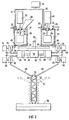
- Figure 1 is a front view of equipment for casting prototype items in engineering plastics materials;
- Figure 2 is a diagram for explaining the construction and operation of a mechanism forming part of the Figure 1 equipment and operable for mixing and dispensing plastics material intermediates;
- Figures 3 and 4 are respective sectional views of part of the Figure 2 mechanism on lines III-III and IV-IV of Figure 5;
- Figure 5 is a plan view of part of the Figure 2 mechanism; and
- Figure 6 is a diagram of parts of the Figure 1 apparatus.
-
- The Figure 1 equipment comprises a
cabinet 1 divided into fourcompartments compartments compartments compartments compartment 5, which contains electro-mechanical control items and electronic control and computing apparatus (not shown), has a front panel supporting an emergency cut-offbutton 7 and a touchscreen control panel 8. - The
compartment 5 contains electrical machinery including avacuum pump 9 while thecompartment 2 contains amechanism 10 for mixing and dispensing plastics material intermediates. Thecompartments sturdy floor plate 11 strong enough for the two compartments to remain sealed one from the other despite a substantial difference in vacuum within the two. Theplate 11 could be made of aluminium or other suitable material. Avalve 100 with amotor drive 101 is mounted in theplate 11 to permit the pressure incompartments - The intermediates comprise thermoplastic materials with or without fillers. The intermediates are chosen to give the desired mechanical properties of the material of the cast component, i.e. the hardness or Durometer reading and related properties such as tensile modulus, resilience, plasticity, compression resistance and elasticity. For example, the intermediates might comprise commercially available materials such as Caprolactum along with the appropriate activators and catalysts. These components are intended to produce a polyamide plastics material with particular, mechanical properties, namely a relatively rigid material. The activator and catalyst might be replaced by an alternative catalyst and activator in specific proportions to give different properties, for example a relatively tougher plastics material. Also, fibrous material or filler, e.g. glass fibre, may be added to give a fibre reinforced plastics material cast component.
- As shown in the diagrammatic view of Figure 2, the
mechanism 10 comprises twoclosable reservoirs lid 22. A gas-tight bearing 23 is provided in thelid 22 of each reservoir to receive ashaft 24 carrying, inside the reservoir, amixer paddle 25. Outside the respective reservoir, eachshaft 24 is coupled to a respectiveelectric motor 26. The lids of the reservoirs also haveopenings 27 into which there can be mounted respective funnels 28 (one is shown in the opening 27 of reservoir 21) or respective screwed plugs 29 (one is shown in the opening 27 of reservoir 22). - In use of the
mechanism 10 thefunnels 28 are fitted to enable the reservoirs to be filled with the required amounts of the chosen intermediates. Thefunnels 28 are then removed and replaced with thescrewed plugs 29 to seal the reservoirs. - The reservoirs are connected via
respective gas taps 30 mounted in thelids 22 andflexible tubing 31 to asupply 32 of inert gas such as nitrogen or argon for forming a gas blanket over the contents of the reservoirs when the mechanism is in use. - A heater, here illustrated as two electrical
resistance heating elements electrical power 35 and located beneath respective ones of thereservoirs - The
mechanism 10 also comprises twocylinders respective pistons pistons respective piston rods motorised drive mechanism 42. - The
mechanism 42 could be replaced by two separate mechanisms one for each cylinder. In either case, thecylinders - Each of the
cylinders conduits valve 45 to aport 46 in the floor of the corresponding one of the tworeservoirs conduit 47 and avalve 48 to one of twoconduits 49, one for each cylinder. Theconduits 49 terminate near each other at anexit fitment 51. -
Heater elements valves conduits cylinders - In operation, the two
reservoirs funnels 28, the appropriate intermediates are inserted. With theclosure plugs 29 fitted and the gas blankets applied, the intermediates are then raised to the appropriate temperature, melting them if they are in the solid phase, and mixed by energising the mixerpaddle drive motors 26. The mixed molten components are then drawn viavalves 45 andconduits cylinders pistons pistons valves 48 andconduits exit fitment 51. - The two
valves 45 are coupled torespective drive units 54 while the twovalves 48 are coupled torespective drive units 58. Thedrive units drive 42 coupled to thepistons reservoirs cylinders conduits 49 as appropriate. As a safety feature, the valves may be operable so that, if the mixer tube is blocked say, the contents of the cylinders are transferred back to thereservoirs - The
conduits 49 extend at specific angles to the vertical (60° for example) and the exit ends to the conduits are at a specific distance one from another so that the contents of the reservoirs exit from theconduits 49 as respective streams which impinge together and become mixed. If required, astatic mixing tube 52, i.e. a tube incorporating angled baffles 53, can be coupled to thefitment 51. - The
tube 52 leads down to amould 60 positioned in thecompartment 3 below themechanism 10. If the mixing tube is not used, a plain plastics tube (not shown) may be used to conduct the molten plastics material down to themould 60 or the impinging streams exiting from theconduits mould 60. This also enables the connection of widely differing mould sizes and geometries and gating points to the material outlet. - As shown in Figures 3, 4 and 5, the
reservoirs solid metal block 62, theblock 62 being clamped by bolts (not shown) to the top of anothersolid metal block 63. Thelids 22 andmotors 26 are not shown in Figures 3 and 4. In Figure 5, alid 22 is shown fitted over the top ofreservoir 21 whilereservoir 20 is shown open. Themotors 26 andpaddles 25 are also not shown in this figure. The bottoms of the through bores are closed byblock 63 withrespective gaskets 64 therebetween. Respective side-by-side horizontal bores are provided inblock 63 to form thecylinders - In Figures 3 and 4, the
cylinder 37 is hidden behindcylinder 36 and underneathreservoir 21. It is generally the same ascylinder 36. - The
pistons cylinders motor drive 42 is operable to move the pistons by different distances dependent upon the quantities of the intermediates in the two reservoirs and to be mixed. This is done by providing a motor drive withrespective motors 50 coupled via a suitable drive mechanism to the two pistons or by a single motor with a differential drive mechanism. In each case, the drive mechanism can comprise a ball-screw drive and the or each motor can comprise a stepper motor. Thevalves conduits metal 70 bolted to the end face ofblock 63 so as to cover the forward ends of thecylinders gasket 71 being provided between theblock 70 and each cylinder. Thedrive units valves metal spacer 73 to block 62. Thedrive units cylindrical valve members 74 of thevalves valve rods 75, preferably with a degree of flexibility in the rods to take up any misalignment of thevalve members 74 in the valve seats 76. Theheating elements various blocks 62 and/or 63. The object of providing the reservoirs, cylinders, conduits and valves in relatively massive, bolted together blocks of metal is to achieve even temperature and less differential expansion of the parts of the mechanism. - Referring back to Figure 1, the
mould 60 is located incompartment 3 supported on a hydraulic or manual or electric lifting platform 80. Themould 60 is a silicon rubber mould, for example the kind of mould which is made by embedding a prototype of an article to be moulded, or an existing item to be copied in liquid silicon mould making material in a mould box and allowing the material to set. The mould is then cut, for example, by hand using a sharp knife, to divide the mould in two parts so that the prototype or original item can be removed. The two parts of the mould are then placed together and secured, for example, by wrapping adhesive tape around them. A mould entry aperture and overflow apertures are also provided, either by post-forming or by providing suitable plugs in the mould box. - The
mould 60 could be of polyurethane rubber or other suitable 'soft' material. Alternatively it could be a rigid mould, for example made of cast epoxy, sprayed or cast metal, or made by machining. - To carry out a moulding operation, the
mould 60 is installed and thereservoirs reservoirs doors 6 closed, the equipment is set-up using thecontrol touch panel 8 to carry out the operation automatically. As noted, this involves heating the contents ofreservoirs - It may be desirable in some cases to maintain a vacuum within the
compartment 2 but this is not always essential. However, for the described embodiment of the invention, a differential is maintained between the vacuum pressure of thecompartments mechanism 10 to themould 60. By way of preferred example, thechamber 2 could be maintained at a pressure of -0.9 Bar (i.e. 90% vacuum) while thecompartment 3 is kept at a pressure of -1.0 Bar (100% vacuum). However, these values of differential vacuum can be changed depending upon choice having regard to factors such as the particular plastics material used and, and mould cavity geometries appertaining to filling. - Figure 6 shows a diagrammatic view of the
chambers pressure equalising valve 100 andmotor drive 101 is shown as are themechanism 10 andmould 60 in the top andbottom chambers pneumatic supply 102, i.e. an inlet supplying air at about 70 kPa (10 pounds per square inch) leads to thedrives 54 and 58 (not shown in Figure 6) within themechanism 10 for controlling thevalves motor drive 101 could also be pneumatically driven and receive thissupply 102 if desired.Item 103 is a simple analogue pressure gauge connected to thechamber 2 and useful during setting up of the equipment for checking the readings of pressure supplied bypressure transducer 105 to the electronic control and computing apparatus within chamber 5 (not shown in Figure 6).Valve 104 with a drive unit (not shown) controlled manually or by the control apparatus enables the vacuum build up inchamber 2 to be released. - A
further pressure transducer 106 is coupled tochamber 3 to provide pressure readings to the control apparatus and this chamber is also coupled to thevacuum pump 9. The vacuum built up within thechamber 3 can be released viavalve 107.Valve 107 can be relatively larger than thevalve 104 to permit a relatively "fast leak" of thechamber 3 vacuum and a "slow leak" of thechamber 2 vacuum. - A vacuum line (not shown) to the
chamber 2 can be provided if required, e.g. to facilitate operation with different levels of vacuum both below ambient as described earlier. - In operation, the plastics intermediates may be melted and mixed whilst both chambers are at ambient pressure and the molten mixture transferred to the mould whilst the
upper chamber 2 is at ambient pressure and thelower chamber 3 is under a vacuum, say at circa 27 kPa (200 mm of mercury). When the mould is filled, e.g. evidenced by the plastics material having just started to emerge from appropriate apertures in the mould, filling ceases and thevalve 100 opened to equalise the pressure in thechambers valves - The apparatus shown can be used both in a differential pressure mode, i.e. with different levels of vacuum in the
compartments
Claims (6)
- Apparatus for making a moulded thermoplastics material article, the apparatus comprising a plurality of reservoirs (20,21) for receiving respective polymer thermoplastics intermediate components, heating means (33, 34) for melting said components in said reservoirs and maintaining them heated, mixing means (26, 25) for mixing the molten contents of the respective reservoirs; piston and cylinder means for transferring the reservoir contents out of the reservoirs, support means for supporting a rigid or soft rubber (60) moulding, and dispensing means (51, 52) for dispensing said plastics material into a rigid or soft rubber mould (60) supported by said support means, characterised in that said apparatus comprises:said piston and cylinder means comprising, for each reservoir, a cylinder (37, 36) connected to the respective reservoir via a first valve (45) and to said dispensing means (52) via a second valve (48), and a piston (38, 39) connected to common drive means (42) for said pump means to supply respective controlled synchronised amounts of the contents of the reservoirs.a first compartment (2) containing said reservoirs, said heating means, said mixing means and pump means;a second compartment (3) sealed from said first compartment and containing said support means and said dispensing means; anda vacuum pump and control means (7, 8, 9) for maintaining the ambient pressure in the second compartment less than the ambient pressure in the first-compartment;
- Apparatus according to claim 1, wherein the vacuum pump and control means are operable for maintaining the ambient pressure in each of the two compartments less than atmospheric pressure.
- Apparatus according to claim 1 or 2, wherein said mould is a silicon or polyurethane rubber mould.
- Apparatus according to any preceding claim, wherein said dispensing means comprises mixing means operable for mixing said plastics material before dispensing it to said mould.
- Apparatus according to claim 4, wherein said dispensing means (52) comprises a static mixing tube (53).
- Apparatus according to any preceding claim, wherein said reservoirs and said cylinders are formed in respective metal blocks (62, 63), said heating means (33, 34) being coupled to said blocks for heating the blocks.
Applications Claiming Priority (2)
| Application Number | Priority Date | Filing Date | Title |
|---|---|---|---|
| GB0200313 | 2002-01-08 | ||
| GBGB0200313.5A GB0200313D0 (en) | 2002-01-08 | 2002-01-08 | Moulded plastics articles |
Publications (2)
| Publication Number | Publication Date |
|---|---|
| EP1325801A1 EP1325801A1 (en) | 2003-07-09 |
| EP1325801B1 true EP1325801B1 (en) | 2005-08-17 |
Family
ID=9928743
Family Applications (1)
| Application Number | Title | Priority Date | Filing Date |
|---|---|---|---|
| EP03250085A Expired - Lifetime EP1325801B1 (en) | 2002-01-08 | 2003-01-08 | Apparatus for making moulded plastics articles |
Country Status (5)
| Country | Link |
|---|---|
| EP (1) | EP1325801B1 (en) |
| AT (1) | ATE302105T1 (en) |
| DE (1) | DE60301278T2 (en) |
| ES (1) | ES2249684T3 (en) |
| GB (2) | GB0200313D0 (en) |
Families Citing this family (5)
| Publication number | Priority date | Publication date | Assignee | Title |
|---|---|---|---|---|
| EP1543995A1 (en) * | 2003-12-18 | 2005-06-22 | Ford Global Technologies, LLC | Method for making plastic products and product made by such a method |
| DE102005051205A1 (en) | 2005-10-18 | 2007-04-19 | Adolf Würth GmbH & Co. KG | Making articles from thermoplastic polymer material comprises separately heating a monomer component and another component, mixing the components and pouring the mixture into a mold |
| EP2033755A1 (en) * | 2007-09-05 | 2009-03-11 | MCP-HEK Tooling GmbH | Device for manufacturing moulded bodies made of plastic |
| DE102008044871B4 (en) * | 2008-08-29 | 2017-03-30 | Alexander Hagmann | Vacuum casting plant, mixing head for a vacuum casting plant and method for this |
| NL2012572B1 (en) * | 2014-04-04 | 2016-03-08 | Heerema Marine Contractors Nl | System and method of manufacturing a Field Joint Coating. |
Family Cites Families (22)
| Publication number | Priority date | Publication date | Assignee | Title |
|---|---|---|---|---|
| US2946488A (en) * | 1957-12-26 | 1960-07-26 | August L Kraft | Metering and dispensing systems |
| BE639110A (en) * | 1962-11-29 | |||
| NL133664C (en) * | 1966-04-29 | |||
| FR2003090A1 (en) * | 1968-03-02 | 1969-11-07 | Basf Ag | |
| CH479654A (en) * | 1968-03-02 | 1969-10-15 | Basf Ag | Method and device for the production of polyamide moldings |
| CH504942A (en) * | 1969-01-18 | 1971-03-31 | Pfeiffer Vakuumtechnik | Plant for casting resin processing |
| DE2108759C3 (en) * | 1971-02-24 | 1985-11-14 | Handtmann, H. Arthur, 7950 Biberach | Process for the continuous production of moldings by the activated anionic polymerization of laurolactam |
| US3970732A (en) * | 1973-09-26 | 1976-07-20 | Kimball International, Inc. | Method of molding rigid foamed polyurethane articles |
| DE2808183A1 (en) * | 1978-02-25 | 1979-09-06 | Hedrich Vakuumanlagen Wilhelm | DEVICES FOR CAST RESIN PLANTS TO CONTROL THE SAME AND / OR DIFFERENT, ALSO SYNCHRONIZED EMISSION QUANTITIES OF FLOWABLE TO HIGHLY VISCOSE MEDIA |
| CA1213114A (en) * | 1982-09-30 | 1986-10-28 | Richard G. Angell, Jr. | Process for fabricating thermoset resin articles |
| JPS61121903A (en) * | 1984-11-20 | 1986-06-09 | Matsushita Electric Ind Co Ltd | Manufacture of molded product |
| JPS61217218A (en) * | 1985-03-22 | 1986-09-26 | Toyota Motor Corp | Reaction injection molding |
| WO1987001328A1 (en) * | 1985-09-02 | 1987-03-12 | Sanai Co., Ltd | Automatic vacuum resin molding apparatus |
| WO1987006878A1 (en) * | 1986-05-16 | 1987-11-19 | Sanai Co., Ltd | Vacuum system for trial molding machines |
| GB8916751D0 (en) * | 1989-07-21 | 1989-09-06 | Babcock Transformers Limited | Producing moulded castings in polymer materials |
| US5100699A (en) * | 1989-08-24 | 1992-03-31 | Minnesota Mining And Manufacturing Company | Method and apparatus for precision pumping, ratioing, and dispensing of work fluid(s) |
| DE4119415A1 (en) * | 1991-06-13 | 1992-12-17 | Huebers Verfahrenstech | METHOD FOR TRANSPORTING AND PREPARING AND FILLING A CASTING SYSTEM WITH CASTING RESIN, AND DEVICE FOR IMPLEMENTING THE PROCESS |
| US5275545A (en) * | 1992-02-26 | 1994-01-04 | Kabushiki Kaisha San-Al | Vacuum cast molding apparatus |
| JP2982564B2 (en) * | 1993-06-19 | 1999-11-22 | 豊田合成株式会社 | Method of forming integral skin foam |
| JPH08276440A (en) * | 1995-04-03 | 1996-10-22 | Bando Chem Ind Ltd | Casting method and casting device for polyurethane molded product |
| JPH09201829A (en) * | 1996-01-26 | 1997-08-05 | Mitsubishi Electric Corp | Resin injection device |
| DE10030874C2 (en) * | 2000-06-23 | 2002-11-07 | Mk Technology Gmbh | Method and device for producing plastic parts by means of vacuum casting |
-
2002
- 2002-01-08 GB GBGB0200313.5A patent/GB0200313D0/en not_active Ceased
-
2003
- 2003-01-08 ES ES03250085T patent/ES2249684T3/en not_active Expired - Lifetime
- 2003-01-08 AT AT03250085T patent/ATE302105T1/en not_active IP Right Cessation
- 2003-01-08 GB GB0300407A patent/GB2386859A/en not_active Withdrawn
- 2003-01-08 DE DE60301278T patent/DE60301278T2/en not_active Expired - Lifetime
- 2003-01-08 EP EP03250085A patent/EP1325801B1/en not_active Expired - Lifetime
Also Published As
| Publication number | Publication date |
|---|---|
| GB0200313D0 (en) | 2002-02-20 |
| DE60301278T2 (en) | 2006-06-29 |
| GB0300407D0 (en) | 2003-02-05 |
| ES2249684T3 (en) | 2006-04-01 |
| DE60301278D1 (en) | 2005-09-22 |
| GB2386859A (en) | 2003-10-01 |
| ATE302105T1 (en) | 2005-09-15 |
| EP1325801A1 (en) | 2003-07-09 |
Similar Documents
| Publication | Publication Date | Title |
|---|---|---|
| US5605707A (en) | Molding apparatus and a method of using the same | |
| US4256444A (en) | Plant for injection molding of thermosetting epoxy plastics | |
| CA1157361A (en) | Method and apparatus for producing foamed panels | |
| US3621892A (en) | Resin vacuum degassing and dispensing system and method | |
| US4714579A (en) | Method and an apparatus for the production of shaped articles | |
| US20080305205A1 (en) | Liquid supply system | |
| EP1325801A1 (en) | Moulded plastics articles | |
| US5002475A (en) | Reaction injection molding apparatus | |
| KR100190349B1 (en) | Method and system for injection molding utilizing pressurized fluid source within a chamber in the mold | |
| US5551486A (en) | Method and equipment for filing casting molds with casting resin or similarly casting-ready liquid media | |
| US6218458B1 (en) | Method and apparatus for producing gas occlusion-free and void-free compounds and composites | |
| EP1140453A1 (en) | Rotational moulding method and apparatus | |
| AU2009260122B2 (en) | Improved injection and or dosing system | |
| GB2084036A (en) | Mixing apparatus for the discontinuous production of plastics foam bodies | |
| US6046267A (en) | Method and apparatus for producing gas occlusion-free and void-free compounds and composites | |
| US4037758A (en) | Mold filling system | |
| JP2521620B2 (en) | Method and device for injection of molding material | |
| US5082437A (en) | Reaction injection machine utilizing a plurality of reactant liquids | |
| US20120211922A1 (en) | Device for processing rapid polymeric reaction systems | |
| GB2213763A (en) | Actuating mould transporting means, in response to a mould fill sensor | |
| CA2095886C (en) | Continuous casting process and apparatus using two moving belts | |
| IE991090A1 (en) | Rotational Moulding | |
| Gillespie | Automatic processing of a glass microballoon filled resin system | |
| JPS6169406A (en) | Reactive injection molding method and device thereof | |
| JPH07232343A (en) | Reaction injection molding of thermosetting resin |
Legal Events
| Date | Code | Title | Description |
|---|---|---|---|
| PUAI | Public reference made under article 153(3) epc to a published international application that has entered the european phase |
Free format text: ORIGINAL CODE: 0009012 |
|
| AK | Designated contracting states |
Designated state(s): AT BE BG CH CY CZ DE DK EE ES FI FR GB GR HU IE IT LI LU MC NL PT SE SI SK TR |
|
| AX | Request for extension of the european patent |
Extension state: AL LT LV MK RO |
|
| RIN1 | Information on inventor provided before grant (corrected) |
Inventor name: FROHN, HEINER-HELMUT Inventor name: FLEGEL, WOLFGANG Inventor name: SCHOENEBORN, HENNER Inventor name: SIMMONDS, RONALD |
|
| 17P | Request for examination filed |
Effective date: 20040108 |
|
| AKX | Designation fees paid |
Designated state(s): AT BE BG CH CY CZ DE DK EE ES FI FR GB GR HU IE IT LI LU MC NL PT SE SI SK TR |
|
| 17Q | First examination report despatched |
Effective date: 20040226 |
|
| GRAP | Despatch of communication of intention to grant a patent |
Free format text: ORIGINAL CODE: EPIDOSNIGR1 |
|
| RTI1 | Title (correction) |
Free format text: APPARATUS FOR MAKING MOULDED PLASTICS ARTICLES |
|
| GRAS | Grant fee paid |
Free format text: ORIGINAL CODE: EPIDOSNIGR3 |
|
| GRAA | (expected) grant |
Free format text: ORIGINAL CODE: 0009210 |
|
| AK | Designated contracting states |
Kind code of ref document: B1 Designated state(s): AT BE BG CH CY CZ DE DK EE ES FI FR GB GR HU IE IT LI LU MC NL PT SE SI SK TR |
|
| PG25 | Lapsed in a contracting state [announced via postgrant information from national office to epo] |
Ref country code: SI Free format text: LAPSE BECAUSE OF FAILURE TO SUBMIT A TRANSLATION OF THE DESCRIPTION OR TO PAY THE FEE WITHIN THE PRESCRIBED TIME-LIMIT Effective date: 20050817 Ref country code: FI Free format text: LAPSE BECAUSE OF FAILURE TO SUBMIT A TRANSLATION OF THE DESCRIPTION OR TO PAY THE FEE WITHIN THE PRESCRIBED TIME-LIMIT Effective date: 20050817 Ref country code: SK Free format text: LAPSE BECAUSE OF FAILURE TO SUBMIT A TRANSLATION OF THE DESCRIPTION OR TO PAY THE FEE WITHIN THE PRESCRIBED TIME-LIMIT Effective date: 20050817 Ref country code: TR Free format text: LAPSE BECAUSE OF FAILURE TO SUBMIT A TRANSLATION OF THE DESCRIPTION OR TO PAY THE FEE WITHIN THE PRESCRIBED TIME-LIMIT Effective date: 20050817 Ref country code: NL Free format text: LAPSE BECAUSE OF FAILURE TO SUBMIT A TRANSLATION OF THE DESCRIPTION OR TO PAY THE FEE WITHIN THE PRESCRIBED TIME-LIMIT Effective date: 20050817 Ref country code: AT Free format text: LAPSE BECAUSE OF FAILURE TO SUBMIT A TRANSLATION OF THE DESCRIPTION OR TO PAY THE FEE WITHIN THE PRESCRIBED TIME-LIMIT Effective date: 20050817 Ref country code: EE Free format text: LAPSE BECAUSE OF FAILURE TO SUBMIT A TRANSLATION OF THE DESCRIPTION OR TO PAY THE FEE WITHIN THE PRESCRIBED TIME-LIMIT Effective date: 20050817 Ref country code: CZ Free format text: LAPSE BECAUSE OF FAILURE TO SUBMIT A TRANSLATION OF THE DESCRIPTION OR TO PAY THE FEE WITHIN THE PRESCRIBED TIME-LIMIT Effective date: 20050817 |
|
| REG | Reference to a national code |
Ref country code: GB Ref legal event code: FG4D |
|
| REG | Reference to a national code |
Ref country code: CH Ref legal event code: EP |
|
| REG | Reference to a national code |
Ref country code: IE Ref legal event code: FG4D |
|
| REF | Corresponds to: |
Ref document number: 60301278 Country of ref document: DE Date of ref document: 20050922 Kind code of ref document: P |
|
| PG25 | Lapsed in a contracting state [announced via postgrant information from national office to epo] |
Ref country code: BG Free format text: LAPSE BECAUSE OF FAILURE TO SUBMIT A TRANSLATION OF THE DESCRIPTION OR TO PAY THE FEE WITHIN THE PRESCRIBED TIME-LIMIT Effective date: 20051117 Ref country code: SE Free format text: LAPSE BECAUSE OF FAILURE TO SUBMIT A TRANSLATION OF THE DESCRIPTION OR TO PAY THE FEE WITHIN THE PRESCRIBED TIME-LIMIT Effective date: 20051117 Ref country code: GR Free format text: LAPSE BECAUSE OF FAILURE TO SUBMIT A TRANSLATION OF THE DESCRIPTION OR TO PAY THE FEE WITHIN THE PRESCRIBED TIME-LIMIT Effective date: 20051117 Ref country code: DK Free format text: LAPSE BECAUSE OF FAILURE TO SUBMIT A TRANSLATION OF THE DESCRIPTION OR TO PAY THE FEE WITHIN THE PRESCRIBED TIME-LIMIT Effective date: 20051117 |
|
| PG25 | Lapsed in a contracting state [announced via postgrant information from national office to epo] |
Ref country code: IE Free format text: LAPSE BECAUSE OF NON-PAYMENT OF DUE FEES Effective date: 20060109 |
|
| REG | Reference to a national code |
Ref country code: CH Ref legal event code: NV Representative=s name: WILLIAM BLANC & CIE CONSEILS EN PROPRIETE INDUSTRI |
|
| PG25 | Lapsed in a contracting state [announced via postgrant information from national office to epo] |
Ref country code: PT Free format text: LAPSE BECAUSE OF FAILURE TO SUBMIT A TRANSLATION OF THE DESCRIPTION OR TO PAY THE FEE WITHIN THE PRESCRIBED TIME-LIMIT Effective date: 20060117 |
|
| PG25 | Lapsed in a contracting state [announced via postgrant information from national office to epo] |
Ref country code: MC Free format text: LAPSE BECAUSE OF NON-PAYMENT OF DUE FEES Effective date: 20060131 Ref country code: LU Free format text: LAPSE BECAUSE OF NON-PAYMENT OF DUE FEES Effective date: 20060131 |
|
| NLV1 | Nl: lapsed or annulled due to failure to fulfill the requirements of art. 29p and 29m of the patents act | ||
| PG25 | Lapsed in a contracting state [announced via postgrant information from national office to epo] |
Ref country code: HU Free format text: LAPSE BECAUSE OF FAILURE TO SUBMIT A TRANSLATION OF THE DESCRIPTION OR TO PAY THE FEE WITHIN THE PRESCRIBED TIME-LIMIT Effective date: 20060218 |
|
| REG | Reference to a national code |
Ref country code: ES Ref legal event code: FG2A Ref document number: 2249684 Country of ref document: ES Kind code of ref document: T3 |
|
| ET | Fr: translation filed | ||
| PLBE | No opposition filed within time limit |
Free format text: ORIGINAL CODE: 0009261 |
|
| STAA | Information on the status of an ep patent application or granted ep patent |
Free format text: STATUS: NO OPPOSITION FILED WITHIN TIME LIMIT |
|
| 26N | No opposition filed |
Effective date: 20060518 |
|
| REG | Reference to a national code |
Ref country code: IE Ref legal event code: MM4A |
|
| PGFP | Annual fee paid to national office [announced via postgrant information from national office to epo] |
Ref country code: CH Payment date: 20070112 Year of fee payment: 5 |
|
| PGFP | Annual fee paid to national office [announced via postgrant information from national office to epo] |
Ref country code: BE Payment date: 20070223 Year of fee payment: 5 |
|
| BERE | Be: lapsed |
Owner name: *MCP TOOLING TECHNOLOGIES LTD Effective date: 20080131 |
|
| REG | Reference to a national code |
Ref country code: CH Ref legal event code: PL |
|
| PG25 | Lapsed in a contracting state [announced via postgrant information from national office to epo] |
Ref country code: CH Free format text: LAPSE BECAUSE OF NON-PAYMENT OF DUE FEES Effective date: 20080131 Ref country code: LI Free format text: LAPSE BECAUSE OF NON-PAYMENT OF DUE FEES Effective date: 20080131 |
|
| PG25 | Lapsed in a contracting state [announced via postgrant information from national office to epo] |
Ref country code: CY Free format text: LAPSE BECAUSE OF FAILURE TO SUBMIT A TRANSLATION OF THE DESCRIPTION OR TO PAY THE FEE WITHIN THE PRESCRIBED TIME-LIMIT Effective date: 20050817 |
|
| PG25 | Lapsed in a contracting state [announced via postgrant information from national office to epo] |
Ref country code: BE Free format text: LAPSE BECAUSE OF NON-PAYMENT OF DUE FEES Effective date: 20080131 |
|
| REG | Reference to a national code |
Ref country code: ES Ref legal event code: PC2A |
|
| REG | Reference to a national code |
Ref country code: FR Ref legal event code: CD |
|
| PG25 | Lapsed in a contracting state [announced via postgrant information from national office to epo] |
Ref country code: IT Free format text: LAPSE BECAUSE OF NON-PAYMENT OF DUE FEES Effective date: 20090108 |
|
| PGRI | Patent reinstated in contracting state [announced from national office to epo] |
Ref country code: IT Effective date: 20110616 |
|
| REG | Reference to a national code |
Ref country code: DE Ref legal event code: R082 Ref document number: 60301278 Country of ref document: DE Representative=s name: WUESTHOFF & WUESTHOFF PATENT- UND RECHTSANWAEL, DE |
|
| REG | Reference to a national code |
Ref country code: GB Ref legal event code: 732E Free format text: REGISTERED BETWEEN 20121101 AND 20121107 |
|
| REG | Reference to a national code |
Ref country code: DE Ref legal event code: R082 Ref document number: 60301278 Country of ref document: DE Representative=s name: WUESTHOFF & WUESTHOFF PATENT- UND RECHTSANWAEL, DE Effective date: 20121127 Ref country code: DE Ref legal event code: R081 Ref document number: 60301278 Country of ref document: DE Owner name: RENISHAW PLC, GB Free format text: FORMER OWNER: MTT TECHNOLOGIES LTD., STONE, GB Effective date: 20121127 Ref country code: DE Ref legal event code: R081 Ref document number: 60301278 Country of ref document: DE Owner name: RENISHAW PLC, WOTTON-UNDER-EDGE, GB Free format text: FORMER OWNER: MTT TECHNOLOGIES LTD., STONE, STAFFORDSHIRE, GB Effective date: 20121127 Ref country code: DE Ref legal event code: R082 Ref document number: 60301278 Country of ref document: DE Representative=s name: WUESTHOFF & WUESTHOFF, PATENTANWAELTE PARTG MB, DE Effective date: 20121127 |
|
| REG | Reference to a national code |
Ref country code: ES Ref legal event code: PC2A Owner name: RENISHAW PLC Effective date: 20130121 |
|
| REG | Reference to a national code |
Ref country code: FR Ref legal event code: TP Owner name: RENISHAW PLC, GB Effective date: 20130820 |
|
| REG | Reference to a national code |
Ref country code: FR Ref legal event code: PLFP Year of fee payment: 14 |
|
| REG | Reference to a national code |
Ref country code: FR Ref legal event code: PLFP Year of fee payment: 15 |
|
| PGFP | Annual fee paid to national office [announced via postgrant information from national office to epo] |
Ref country code: DE Payment date: 20170120 Year of fee payment: 15 Ref country code: FR Payment date: 20170120 Year of fee payment: 15 |
|
| PGFP | Annual fee paid to national office [announced via postgrant information from national office to epo] |
Ref country code: ES Payment date: 20170113 Year of fee payment: 15 Ref country code: IT Payment date: 20170124 Year of fee payment: 15 |
|
| REG | Reference to a national code |
Ref country code: DE Ref legal event code: R119 Ref document number: 60301278 Country of ref document: DE |
|
| PG25 | Lapsed in a contracting state [announced via postgrant information from national office to epo] |
Ref country code: FR Free format text: LAPSE BECAUSE OF NON-PAYMENT OF DUE FEES Effective date: 20180131 Ref country code: DE Free format text: LAPSE BECAUSE OF NON-PAYMENT OF DUE FEES Effective date: 20180801 |
|
| REG | Reference to a national code |
Ref country code: FR Ref legal event code: ST Effective date: 20180928 |
|
| PG25 | Lapsed in a contracting state [announced via postgrant information from national office to epo] |
Ref country code: IT Free format text: LAPSE BECAUSE OF NON-PAYMENT OF DUE FEES Effective date: 20180108 |
|
| PGFP | Annual fee paid to national office [announced via postgrant information from national office to epo] |
Ref country code: GB Payment date: 20190130 Year of fee payment: 17 |
|
| REG | Reference to a national code |
Ref country code: ES Ref legal event code: FD2A Effective date: 20190730 |
|
| PG25 | Lapsed in a contracting state [announced via postgrant information from national office to epo] |
Ref country code: ES Free format text: LAPSE BECAUSE OF NON-PAYMENT OF DUE FEES Effective date: 20180109 |
|
| GBPC | Gb: european patent ceased through non-payment of renewal fee |
Effective date: 20200108 |
|
| PG25 | Lapsed in a contracting state [announced via postgrant information from national office to epo] |
Ref country code: GB Free format text: LAPSE BECAUSE OF NON-PAYMENT OF DUE FEES Effective date: 20200108 |