EP1325352B1 - Adaptive measurement correction during remote distance measurement - Google Patents
Adaptive measurement correction during remote distance measurement Download PDFInfo
- Publication number
- EP1325352B1 EP1325352B1 EP01972868A EP01972868A EP1325352B1 EP 1325352 B1 EP1325352 B1 EP 1325352B1 EP 01972868 A EP01972868 A EP 01972868A EP 01972868 A EP01972868 A EP 01972868A EP 1325352 B1 EP1325352 B1 EP 1325352B1
- Authority
- EP
- European Patent Office
- Prior art keywords
- distance
- measurement
- craft
- altitude
- geographical position
- Prior art date
- Legal status (The legal status is an assumption and is not a legal conclusion. Google has not performed a legal analysis and makes no representation as to the accuracy of the status listed.)
- Expired - Lifetime
Links
- 238000005259 measurement Methods 0.000 title claims abstract description 106
- 238000012937 correction Methods 0.000 title claims abstract description 30
- 230000003044 adaptive effect Effects 0.000 title 1
- 238000000034 method Methods 0.000 claims abstract description 26
- 238000004590 computer program Methods 0.000 claims description 4
- 230000005540 biological transmission Effects 0.000 description 4
- XLYOFNOQVPJJNP-UHFFFAOYSA-N water Substances O XLYOFNOQVPJJNP-UHFFFAOYSA-N 0.000 description 4
- 238000004364 calculation method Methods 0.000 description 3
- 238000001514 detection method Methods 0.000 description 1
- 238000005516 engineering process Methods 0.000 description 1
- 238000007429 general method Methods 0.000 description 1
- 238000000691 measurement method Methods 0.000 description 1
- 238000005096 rolling process Methods 0.000 description 1
Images


Classifications
-
- G—PHYSICS
- G01—MEASURING; TESTING
- G01C—MEASURING DISTANCES, LEVELS OR BEARINGS; SURVEYING; NAVIGATION; GYROSCOPIC INSTRUMENTS; PHOTOGRAMMETRY OR VIDEOGRAMMETRY
- G01C21/00—Navigation; Navigational instruments not provided for in groups G01C1/00 - G01C19/00
- G01C21/005—Navigation; Navigational instruments not provided for in groups G01C1/00 - G01C19/00 with correlation of navigation data from several sources, e.g. map or contour matching
-
- G—PHYSICS
- G01—MEASURING; TESTING
- G01C—MEASURING DISTANCES, LEVELS OR BEARINGS; SURVEYING; NAVIGATION; GYROSCOPIC INSTRUMENTS; PHOTOGRAMMETRY OR VIDEOGRAMMETRY
- G01C5/00—Measuring height; Measuring distances transverse to line of sight; Levelling between separated points; Surveyors' levels
- G01C5/005—Measuring height; Measuring distances transverse to line of sight; Levelling between separated points; Surveyors' levels altimeters for aircraft
-
- G—PHYSICS
- G01—MEASURING; TESTING
- G01S—RADIO DIRECTION-FINDING; RADIO NAVIGATION; DETERMINING DISTANCE OR VELOCITY BY USE OF RADIO WAVES; LOCATING OR PRESENCE-DETECTING BY USE OF THE REFLECTION OR RERADIATION OF RADIO WAVES; ANALOGOUS ARRANGEMENTS USING OTHER WAVES
- G01S13/00—Systems using the reflection or reradiation of radio waves, e.g. radar systems; Analogous systems using reflection or reradiation of waves whose nature or wavelength is irrelevant or unspecified
- G01S13/88—Radar or analogous systems specially adapted for specific applications
- G01S13/93—Radar or analogous systems specially adapted for specific applications for anti-collision purposes
- G01S13/933—Radar or analogous systems specially adapted for specific applications for anti-collision purposes of aircraft or spacecraft
- G01S13/935—Radar or analogous systems specially adapted for specific applications for anti-collision purposes of aircraft or spacecraft for terrain-avoidance
-
- G—PHYSICS
- G01—MEASURING; TESTING
- G01S—RADIO DIRECTION-FINDING; RADIO NAVIGATION; DETERMINING DISTANCE OR VELOCITY BY USE OF RADIO WAVES; LOCATING OR PRESENCE-DETECTING BY USE OF THE REFLECTION OR RERADIATION OF RADIO WAVES; ANALOGOUS ARRANGEMENTS USING OTHER WAVES
- G01S7/00—Details of systems according to groups G01S13/00, G01S15/00, G01S17/00
- G01S7/02—Details of systems according to groups G01S13/00, G01S15/00, G01S17/00 of systems according to group G01S13/00
- G01S7/40—Means for monitoring or calibrating
- G01S7/4004—Means for monitoring or calibrating of parts of a radar system
-
- G—PHYSICS
- G01—MEASURING; TESTING
- G01S—RADIO DIRECTION-FINDING; RADIO NAVIGATION; DETERMINING DISTANCE OR VELOCITY BY USE OF RADIO WAVES; LOCATING OR PRESENCE-DETECTING BY USE OF THE REFLECTION OR RERADIATION OF RADIO WAVES; ANALOGOUS ARRANGEMENTS USING OTHER WAVES
- G01S13/00—Systems using the reflection or reradiation of radio waves, e.g. radar systems; Analogous systems using reflection or reradiation of waves whose nature or wavelength is irrelevant or unspecified
- G01S13/88—Radar or analogous systems specially adapted for specific applications
- G01S13/882—Radar or analogous systems specially adapted for specific applications for altimeters
Definitions
- the present invention relates generally to navigating crafts by means of remote distance measurement, where a remote distance meter's inclination to erroneously measure the shortest distance to the surface over which the craft moves is adjusted adaptively.
- the invention relates to a method and an apparatus for navigating a craft according to the preambles of claim 1 and claim 8 respectively.
- the invention also relates to a computer program for performing the method according to claim 1 and a computer readable medium having such program recorded thereon.
- Radar r adio d etecting a nd r anging
- Doppler detection it is also possible to determine radial velocity relationships between the radar and the registered objects.
- Saab NINS - An automated Navigation System by P. Bergljung et al, 1 November, 1999, No. A, Saab Dynamics AB , describes how an aircraft can be navigated based on the appearance of the surface over which the aircraft moves.
- a radar altimeter in the aircraft sends signals towards the surface and determines the altitude over the surface by analyzing the signals being reflected against the surface.
- Information in a database pertaining to the surface's elevation in the area within which the aircraft is located is compared with a latest measured elevation of the surface.
- Conclusions can thereby be drawn as to the aircraft's position.
- a so-called measurement shell represents an uncertainty volume of a predetermined size within which the craft is estimated to be positioned. By repeated measurements and measurement shell assumptions the size of the measurement shell is reduced and the craft's position can be determined with a higher accuracy.
- the Article " SAAB” NINS/NILS - an autonomous landing system for Gripen” by Pucar et al. in IEEE 2000 Position Location and Navigation Symposium, 13-16 March 2000, pp 254-261 is an example of a navigation system which comprises a topographic database and a radar altimeter.
- the radar altimeter does not actually measure the aircraft's altitude above ground but rather a distance to the closest object within a beam width by transmitting a modulated signal toward the ground.
- the time elapsed between transmission of the modulated signal and its reception after reflection on the ground is converted to altitude.
- the measured ground profile beneath the aircraft is compared with the elevation database stored in the aircraft and thereby the position of the aircraft can be found.
- a so-called terrain reference navigation filter which utilizes a radar altimeter and which has been proposed by the applicant, assumes certain characteristics of the noise being associated with the radar measurement.
- the noise is thereby supposed to be due to the fact that the measurement occasionally is not performed with respect to the actual ground surface, but against objects being located on the surface, such as trees, posts and masts.
- the measurement shell is selected with such thickness that the aircraft certainly can be said to be located within the measurement shell irrespective of the noise.
- a radar echo corresponding to a reflection from a knoll in the surface which is located closer to the aircraft than the surface vertically below, however in a direction obliquely below the aircraft, is interpreted as a vertical radar reflection the position information will be erroneous.
- the navigation method presupposes that all remote distance measurements (e.g. performed by means of a radar) are executed vertically below the craft it is thus desirable to reduce the influence of remote distance measurements in other directions as much as possible, since this introduces uncertainty in the navigation method.
- the yet known solutions for radar altitude measurement aided navigation fail to take into account the radar's inclination to measure a distance, which is angularly erroneous with respect to the surface over which the craft moves.
- the object of the present invention is therefore to alleviate the above problems and improve the precision as well as the robustness of the earlier known solutions for remote distance measurement based terrain navigation.
- the object is achieved by a method for measurement noise modeling in a remote distance meter as initially described, wherein the remote distance measurement employs a measurement correction parameter which for each geographical position and altitude designates an estimation of a remote distance meter's inclination to measure a shortest distance between the craft and the surface in a direction which deviates from a desired measurement direction.
- the object is achieved by a computer program, which is directly loadable into the internal memory of a computer, comprising software for performing the steps of any of the method described in the above paragraph, when said program is run on the computer.
- the object is achieved by a computer readable medium, having a program recorded thereon, where the program is to make a computer perform the method proposed in the penultimate paragraph above.
- a measurement correction parameter designates an estimation of a remote distance meter's inclination to measure a shortest distance between the craft and the surface in a direction which deviates from a desired measurement direction.
- a control unit in the apparatus takes the measurement correction parameter into account when calculating the craft's geographical position
- the proposed solution improves both the precision and the reliability during position determination by means of remote distance measurement. This, in turn, results in that the traffic security can be improved in any kind of craft traffic where such positioning is utilized, such as in aircraft navigation and marine navigation, on as well as below the water surface.
- Figure 1 shows an aircraft 100, which is equipped with an apparatus according to the invention.
- the aircraft 100 passes over a terrain segment when the proposed apparatus is activated and a procedure for determining the aircraft's 100 position is instigated.
- a measurement shell set i is assumed, which has a maximum size and typically is a cylindrical volume being several kilometers in width and whose height is arbitrary, within which the aircraft 100 is presumed to be located.
- Figure 2 illustrates how the apparatus in the aircraft 100 in a later stage of the procedure for determining the aircraft's 100 position performs a radar altitude measurement, through which the aircraft's distance in height above the surface is determined.
- the apparatus includes a radar whose transmitter- and receiver antennae have relatively large lobe angles (e.g. 40°-60°) and whose cut area, for instance, may be elliptical.
- the larger the lobe angle the larger the risk of receiving radar reflections from directions which deviate from the desired direction, since any reflection within the range of the antenna lobe may be interpreted as a ground reflection in the desired reference direction irrespective of whether it in fact comes from this direction or not.
- a too small antenna lobe angle will, however, render the radar altimeter sensitive to changes in the direction of the aircraft, e.g. during rolling or tipping.
- the transmitter antenna transmits a radar signal and the receiver antenna, which may be identical with the transmitter antenna, receives a reflected signal.
- the time difference between the transmitted signal and the received signal constitutes a measure of the distance h gnd (i) between the aircraft 100 and the object that reflected the transmitted signal, since the radar signal is presumed to propagate at a constant and known speed, namely the speed of light. According to a basic assumption, it is the ground below the aircraft 100 that has reflected the transmitted signal. The aircraft 100 is thus expected to be located at a distance h gnd (i) above the ground.
- the measurement shell set i can be reduced in height to a particular thickness.
- This thickness is stipulated by an estimated uncertainty in height in the radar altitude measurement.
- the height of any objects located on the surface places a limit as to the thickness of the measurement shell set i .
- the precision of the radar altitude measurement is hence determined by the modeling of the surface's capability to reflect radar signals.
- the lower limit for the thickness of the measurement shell set i is put equal to the height of the highest expected objects on the ground. A decrease of the measurement shell's set i thickness below this limit jeopardizes the robustness of the measurement method, and eventually reduces the precision in the position determination.
- Figure 3 shows a yet later stage of the procedure for determining the aircraft's 100 position, when another radar altitude measurement is performed.
- the height reduced measurement shell set i is expanded to some extent in order to take into consideration the uncertainty in position being introduced due to the movement of the aircraft 100. Furthermore, the measurement shell set i is shifted a distance, which corresponds to the aircraft's 100 estimated movement since the previous radar altitude measurement.
- Sensors in the aircraft 100 for instance in the form of inertial gyros, accelerometers and pressure meters can be used to register such movement.
- the renewed radar altitude measurement provides an updated value of the distance estimation h gnd (i+1) to the ground.
- a new measurement shell set i+1 based on this estimation is assumed.
- the aircraft 100 is thus presupposed to be located within a cut volume set i
- the aircraft's 100 position can thereby be estimated with an accuracy corresponding to the cut volume set i
- the ground's actual elevation h top over the mean sea level is assumed to be registered at certain geographical positions in an orthogonal check pattern with 50 meters distance in each direction between two neighboring coordinate points. This information is stored in a database in the aircraft 100. An estimation of the ground's elevation between the stored positions is preferably calculated by means of bi-linear interpolation.
- Figure 4 shows an aircraft 400, which travels over a ground surface 410.
- the method according to an embodiment of the invention will be exemplified below with reference to the figure 4 .
- the radar having a lobe angle ⁇ in the aircraft 400, risk measuring a shortest radar distance h ter between the aircraft 400 and the ground surface 410 in a different direction ⁇ ⁇ ⁇ than vertically against the mean sea level.
- the radar distance h ter is namely (roughly) registered with respect to the first received signal reflection whose power level exceeds a particular threshold level.
- the shortest radar distance h ter between the aircraft 400 and the ground surface 410 will nevertheless probably be measured against a different point beside both the first geographical position X 0 , Y 0 and the second geographical position X 1 , Y 1 . If, at radar altitude measurement, it is desired to compensate for the radar's inclination to measure a shortest radar distance h ter between the aircraft 400 and the ground surface 410 in a different direction ⁇ than the desired direction it is thus necessary to perform such compensation not only with respect to geographical position X, Y, however also with respect to the flying altitude h msl .
- An embodiment of the invention involves calculation of a corrected radar distance h gnd corr as the sum of an expected measured radar distance h ter and a measurement correction parameter h ⁇ at particular geographical positions X, Y (typically in an orthogonal check pattern with 50 meters distance in each direction between two neighboring coordinate points) and for particular reference altitudes h msl within a certain geographical area (typically a country, a continent or the entire earth).
- a database in the aircraft 400 stores pre-calculated measurement correction parameters h ⁇ for the coordinates X,Y,h msl together with topographical data h top .
- a relevant measurement correction parameter h ⁇ is instead calculated in real time, according to the expression (1), below whenever this parameter is required.
- the measurement correction parameter h ⁇ is calculated, it is determined as a maximum difference between a correct distance h gnd at a particular geographical position and altitude, such as X 0 ,Y 0 and h msl 0 respectively, and an expected erroneously measured distance h ter at this position and altitude. This can be accomplished by calculating the expected erroneously measured distance h ter according to the expression (1).
- X 0 ,Y 0 denotes the particular geographical position
- h msl denotes the particular altitude
- X 1 ,Y 1 denotes the geographical position on the surface against which the remote distance meter is expected to measure an erroneous distance
- h top (X 1 ,Y 1 ) denotes the surface's vertical distance to the mean sea level at the geographical position against which the remote distance meter is expected to measure the erroneous distance.
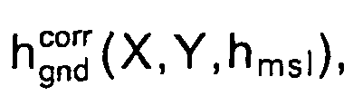
- the aircraft's altitude h msl (X,Y) over the mean sea level can be calculated as the sum of the ground's 410 topographical elevation h top (X,Y) over the mean sea level and the corrected distance h gnd corr X Y h msl .
- the craft's depth underneath the mean sea level can be calculated, in a corresponding manner, as the difference between the bottom's topographical depth d top (X,Y) and a corrected depth d gnd corr X Y h msl .
- the apparatus includes a remote distance meter 510, which typically is constituted by a radar, however also can be a laser distance meter or an acoustical distance meter in the form of, for example a sonar.
- the remote distance meter 510 includes at least one means 511 for transmission and reception of signals.
- the means 511 is thus at least one radar antenna, a laser including a sensor or corresponding sonar sensors.
- the remote distance meter 510 is equipped with two separate means 511 for transmission and reception respectively.
- the remote distance meter 510 delivers values of measured distances h gnd between the craft and the surface over which it moves to a control unit 540.
- the control unit 540 also receives signals h msl , ⁇ X and ⁇ Y from a movement meter 520, which represent estimations of the craft's relative movement in space.
- GPS Global Positioning System
- the movement meter 520 instead preferably includes a pressure meter designed to measure the pressure of the water that surrounds the craft plus, for example, inertial gyros and accelerometers.
- the movement meter 520 includes sensors for registering horizontal movements, i.e. two-dimensional inertial gyros and accelerometers for example.
- control unit 540 retrieves topographical data h top (X,Y) and measurement models N gnd (X,Y) for relevant geographical positions from a database 530.
- control unit 540 moreover retrieves pre-calculated measurement correction parameters h ⁇ (X,Y,h msl ) for relevant geographical positions X,Y from the database 530. According to another embodiment of the invention, the control unit 540 instead calculates a measurement correction parameter h ⁇ (X,Y,h msl ) in real time for relevant geographical positions X,Y.
- the control unit Based on a corrected distance h gnd corr X Y h msl , the signals ⁇ h msl , ⁇ X and ⁇ Y, and the information h top (X,Y) from the database 530 (alternatively: real time calculation in the control unit 540), the movement meter 520 respective the database 530, the control unit then calculates the craft's position according to the procedure described with reference to the figures 1 - 3 above.
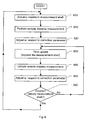
- FIG. 6 shows a flow chart, which illustrates the general method according to the invention that is employed when a craft navigates with aid from remote distance measurement against a surface.
- a first step 600 assumes a measurement shell of maximum size as in the first procedure step described with reference to figure 1 .
- a following step 610 performs a remote distance measurement whereby a measured distance between the craft and the surface is obtained.
- a step 620 thereafter models the remote distance meter's inclination to measure a shortest distance between the craft and the surface over which it moves in a direction that deviates from a desired measurement direction. The distance measured in the step 610 is thereby adjusted by addition of a measurement correction parameter as described above.
- the measurement correction parameter can either be calculated in real time or be pre-calculated for particular coordinate points between which a relevant value is interpolated when necessary.
- a time update takes place due to the movement of the craft whereby the measurement shell is updated.
- a step 640 after that, performs a renewed remote distance measurement and a new distance to the surface is obtained.
- a following step 650 updates also the model pertaining to the remote distance meter's inclination to measure the shortest distance between the craft and the surface over which it moves in a direction which deviates from a desired measurement direction. This update is necessary because the surface beneath the craft has changed since the previous remote distance measurement.
- the distance measured in the step 640 is thereby adjusted by addition of a new measurement correction parameter, which in similarity with the previous measurement correction parameter, either is calculated in real time or has been pre-calculated.
- the measurement shell is reduced according to the procedure earlier described with reference to figure 3 .
- a following step 660 investigates whether the measurement shell has been reduced to an empty volume, i.e. whether there is an overlap between the previous measurement shell and the latest measurement shell. Provided that these measurement shells overlap the position can be determined with an increased accuracy and the procedure is returned to the step 630 for a time update. Otherwise, the procedure is returned to the first step 600, where a maximum sized measurement shell again is assumed.
- the present invention does not preclude that parameters in addition to the suggested measurement correction parameter and the corrected distance are used in order to describe the measurement errors, which are expected to occur during remote distance measurement.
- the invention be combined with a solution where a measurement noise parameter is utilized, which for particular geographical positions designates an estimation of the surface's inclination to cause measurement noise when measuring a distance against it.
Landscapes
- Engineering & Computer Science (AREA)
- Radar, Positioning & Navigation (AREA)
- Remote Sensing (AREA)
- Physics & Mathematics (AREA)
- General Physics & Mathematics (AREA)
- Computer Networks & Wireless Communication (AREA)
- Automation & Control Theory (AREA)
- Aviation & Aerospace Engineering (AREA)
- Electromagnetism (AREA)
- Radar Systems Or Details Thereof (AREA)
- Measurement Of Optical Distance (AREA)
Abstract
Description
- The present invention relates generally to navigating crafts by means of remote distance measurement, where a remote distance meter's inclination to erroneously measure the shortest distance to the surface over which the craft moves is adjusted adaptively. Specifically, the invention relates to a method and an apparatus for navigating a craft according to the preambles of
claim 1 and claim 8 respectively. The invention also relates to a computer program for performing the method according toclaim 1 and a computer readable medium having such program recorded thereon. - It is generally known to utilize radar technology to determine the distance and bearing to objects (radar = radio detecting and ranging). By performing doppler detection it is also possible to determine radial velocity relationships between the radar and the registered objects.
- The article "Saab NINS - An automated Navigation System", by P. Bergljung et al, 1 November, 1999, No. A, Saab Dynamics AB, describes how an aircraft can be navigated based on the appearance of the surface over which the aircraft moves. A radar altimeter in the aircraft sends signals towards the surface and determines the altitude over the surface by analyzing the signals being reflected against the surface. Information in a database pertaining to the surface's elevation in the area within which the aircraft is located is compared with a latest measured elevation of the surface. Conclusions can thereby be drawn as to the aircraft's position. A so-called measurement shell represents an uncertainty volume of a predetermined size within which the craft is estimated to be positioned. By repeated measurements and measurement shell assumptions the size of the measurement shell is reduced and the craft's position can be determined with a higher accuracy.
- The Article "SAAB" NINS/NILS - an autonomous landing system for Gripen" by Pucar et al. in IEEE 2000 Position Location and Navigation Symposium, 13-16 March 2000, pp 254-261, is an example of a navigation system which comprises a topographic database and a radar altimeter. The radar altimeter does not actually measure the aircraft's altitude above ground but rather a distance to the closest object within a beam width by transmitting a modulated signal toward the ground. The time elapsed between transmission of the modulated signal and its reception after reflection on the ground is converted to altitude. The measured ground profile beneath the aircraft is compared with the elevation database stored in the aircraft and thereby the position of the aircraft can be found.
- A so-called terrain reference navigation filter, which utilizes a radar altimeter and which has been proposed by the applicant, assumes certain characteristics of the noise being associated with the radar measurement. The noise is thereby supposed to be due to the fact that the measurement occasionally is not performed with respect to the actual ground surface, but against objects being located on the surface, such as trees, posts and masts. In order to make the terrain reference navigation filter independent of such noise, the measurement shell is selected with such thickness that the aircraft certainly can be said to be located within the measurement shell irrespective of the noise.
- When performing radar altitude measurements an uncertainty arises due to the fact that the signal that is received by the radar might not have been reflected by the surface in a desired reference direction. Most commonly, this direction is set vertically with respect to the mean sea level. An uncertainty is introduced in the measurement as soon as reflections in other directions than the reference direction could be interpreted as reflections in this direction.
- If, for example when performing radar altitude measurement from an aircraft, a radar echo corresponding to a reflection from a knoll in the surface, which is located closer to the aircraft than the surface vertically below, however in a direction obliquely below the aircraft, is interpreted as a vertical radar reflection the position information will be erroneous.
- For reasons of precision, it is of course desirable to minimize the uncertainty area when determining the position for a craft. Since the navigation method presupposes that all remote distance measurements (e.g. performed by means of a radar) are executed vertically below the craft it is thus desirable to reduce the influence of remote distance measurements in other directions as much as possible, since this introduces uncertainty in the navigation method.
- The yet known solutions for radar altitude measurement aided navigation fail to take into account the radar's inclination to measure a distance, which is angularly erroneous with respect to the surface over which the craft moves.
- The object of the present invention is therefore to alleviate the above problems and improve the precision as well as the robustness of the earlier known solutions for remote distance measurement based terrain navigation.
- According to one aspect of the invention the object is achieved by a method for measurement noise modeling in a remote distance meter as initially described, wherein the remote distance measurement employs a measurement correction parameter which for each geographical position and altitude designates an estimation of a remote distance meter's inclination to measure a shortest distance between the craft and the surface in a direction which deviates from a desired measurement direction.
- According to another aspect of the invention the object is achieved by a computer program, which is directly loadable into the internal memory of a computer, comprising software for performing the steps of any of the method described in the above paragraph, when said program is run on the computer.
- According to yet another aspect of the invention the object is achieved by a computer readable medium, having a program recorded thereon, where the program is to make a computer perform the method proposed in the penultimate paragraph above.
- According to still another aspect of the invention the object is achieved by the initially described apparatus, wherein, for each geographical position and altitude, a measurement correction parameter designates an estimation of a remote distance meter's inclination to measure a shortest distance between the craft and the surface in a direction which deviates from a desired measurement direction. A control unit in the apparatus takes the measurement correction parameter into account when calculating the craft's geographical position
- The proposed solution improves both the precision and the reliability during position determination by means of remote distance measurement. This, in turn, results in that the traffic security can be improved in any kind of craft traffic where such positioning is utilized, such as in aircraft navigation and marine navigation, on as well as below the water surface.
- The present invention is now to be explained more closely by means of preferred embodiments, which are disclosed as examples, and with reference to the attached drawings.
- Figure 1
- illustrates how an aircraft equipped with an apparatus according to the invention passes over a terrain segment whereby a first step of a per se known procedure for determining the craft's geographical position is effected,
- Figure 2
- shows a later stage of the procedure according to
figure 1 , for determining the craft's geographical position, - Figure 3
- shows yet a later stage of the procedure according to
figure 1 , - Figure 4
- illustrates, by means of an example, the procedure according to an embodiment of the invention,
- Figure 5
- illustrates an embodiment of the apparatus according to the invention, and
- Figure 6
- illustrates, by means of a flow chart, the general procedure according to the invention, which preferably is controlled by a computer program.
-
Figure 1 shows anaircraft 100, which is equipped with an apparatus according to the invention. Theaircraft 100 passes over a terrain segment when the proposed apparatus is activated and a procedure for determining the aircraft's 100 position is instigated. Initially, a measurement shell seti is assumed, which has a maximum size and typically is a cylindrical volume being several kilometers in width and whose height is arbitrary, within which theaircraft 100 is presumed to be located. -
Figure 2 illustrates how the apparatus in theaircraft 100 in a later stage of the procedure for determining the aircraft's 100 position performs a radar altitude measurement, through which the aircraft's distance in height above the surface is determined. The apparatus includes a radar whose transmitter- and receiver antennae have relatively large lobe angles (e.g. 40°-60°) and whose cut area, for instance, may be elliptical. The larger the lobe angle, the larger the risk of receiving radar reflections from directions which deviate from the desired direction, since any reflection within the range of the antenna lobe may be interpreted as a ground reflection in the desired reference direction irrespective of whether it in fact comes from this direction or not. A too small antenna lobe angle will, however, render the radar altimeter sensitive to changes in the direction of the aircraft, e.g. during rolling or tipping. - The transmitter antenna transmits a radar signal and the receiver antenna, which may be identical with the transmitter antenna, receives a reflected signal. The time difference between the transmitted signal and the received signal constitutes a measure of the distance hgnd(i) between the
aircraft 100 and the object that reflected the transmitted signal, since the radar signal is presumed to propagate at a constant and known speed, namely the speed of light. According to a basic assumption, it is the ground below theaircraft 100 that has reflected the transmitted signal. Theaircraft 100 is thus expected to be located at a distance hgnd(i) above the ground. - By the radar altitude measurement, the measurement shell seti can be reduced in height to a particular thickness. This thickness is stipulated by an estimated uncertainty in height in the radar altitude measurement. The height of any objects located on the surface (in this case the ground) places a limit as to the thickness of the measurement shell seti. The precision of the radar altitude measurement is hence determined by the modeling of the surface's capability to reflect radar signals. Normally, the lower limit for the thickness of the measurement shell seti is put equal to the height of the highest expected objects on the ground. A decrease of the measurement shell's seti thickness below this limit jeopardizes the robustness of the measurement method, and eventually reduces the precision in the position determination.
-
Figure 3 shows a yet later stage of the procedure for determining the aircraft's 100 position, when another radar altitude measurement is performed. The height reduced measurement shell seti is expanded to some extent in order to take into consideration the uncertainty in position being introduced due to the movement of theaircraft 100. Furthermore, the measurement shell seti is shifted a distance, which corresponds to the aircraft's 100 estimated movement since the previous radar altitude measurement. Sensors in theaircraft 100, for instance in the form of inertial gyros, accelerometers and pressure meters can be used to register such movement. - The renewed radar altitude measurement provides an updated value of the distance estimation hgnd(i+1) to the ground. A new measurement shell seti+1 based on this estimation is assumed. When determining the aircraft's 100 position an assumption is made that on one hand the aircraft is located within the shifted and expanded measurement shell seti, and on the other hand is located within the new measurement shell seti+1, which was obtained via the latest radar altitude measurement. The
aircraft 100 is thus presupposed to be located within a cut volume seti|i+1, which overlaps the shifted and expanded measurement shell seti as well as the latest measurement shell seti+1. The aircraft's 100 position can thereby be estimated with an accuracy corresponding to the cut volume seti|i+1. - A further refined position determination for the
aircraft 100 can be obtained by means of repeated measurements of the aircraft's movement, repeated radar altitude measurements and comparisons with registered information pertaining to the ground's elevation htop over the mean sea level at particular geographical positions. Furthermore, an estimation of the aircraft's 100 elevation hmsl over themean sea level 300 can be acquired according to the relationship hmsl = htop + hgnd(i+1). - Typically, the ground's actual elevation htop over the mean sea level is assumed to be registered at certain geographical positions in an orthogonal check pattern with 50 meters distance in each direction between two neighboring coordinate points. This information is stored in a database in the
aircraft 100. An estimation of the ground's elevation between the stored positions is preferably calculated by means of bi-linear interpolation. -
Figure 4 shows anaircraft 400, which travels over aground surface 410. The method according to an embodiment of the invention will be exemplified below with reference to thefigure 4 . When performing a radar altitude measurement against a terrain segment where the ground's 410 elevation varies, such as in this figure, the radar having a lobe angle ϕ in theaircraft 400, risk measuring a shortest radar distance hter between theaircraft 400 and theground surface 410 in a different direction α ≤ ϕ than vertically against the mean sea level. The radar distance hter is namely (roughly) registered with respect to the first received signal reflection whose power level exceeds a particular threshold level. When theaircraft 400 is positioned at areference altitude h msl0 over themean sea level 0 at a first geographical position X0,Y0 it is therefore relatively probable that a radar signal, which has been reflected by theground surface 410 at a second geographical position X1, Y1 is the first received signal whose power level exceeds the threshold level, since at this second geographical position X1, Y1 the distance between theground surface 410 and theaircraft 400 is the shortest. When flying over the same first geographical position X0, Y0, however at a different reference altitude hmsl, the shortest radar distance hter between theaircraft 400 and theground surface 410 will nevertheless probably be measured against a different point beside both the first geographical position X0, Y0 and the second geographical position X1, Y1. If, at radar altitude measurement, it is desired to compensate for the radar's inclination to measure a shortest radar distance hter between theaircraft 400 and theground surface 410 in a different direction α than the desired direction it is thus necessary to perform such compensation not only with respect to geographical position X, Y, however also with respect to the flying altitude hmsl. - An embodiment of the invention involves calculation of a corrected radar distance

aircraft 400 stores pre-calculated measurement correction parameters hΔ for the coordinates X,Y,hmsl together with topographical data htop. - According to another embodiment of the invention, a relevant measurement correction parameter hΔ is instead calculated in real time, according to the expression (1), below whenever this parameter is required.
- Storing a large number of pre-calculated measurement correction parameters hΔ, of course, requires a relatively large database, while real time calculation of the measurement correction parameters hΔ demands a comparatively powerful processor. If measurement correction parameters hΔ are pre-calculated for particular coordinates X,Y,hmsl and if a radar altitude measurement is performed in a point in space, which does not coincide with a registered coordinate X,Y,hmsl, the necessary data is interpolated from corresponding data regarding the closest registered coordinates.
- Irrespective of when the measurement correction parameter hΔ is calculated, it is determined as a maximum difference between a correct distance hgnd at a particular geographical position and altitude, such as X0,Y0 and
h msl0 respectively, and an expected erroneously measured distance hter at this position and altitude. This can be accomplished by calculating the expected erroneously measured distance hter according to the expression (1).
where X0,Y0 denotes the particular geographical position,
hmsl denotes the particular altitude,
X1,Y1 denotes the geographical position on the surface against which the remote distance meter is expected to measure an erroneous distance, and
htop(X1,Y1) denotes the surface's vertical distance to the mean sea level at the geographical position against which the remote distance meter is expected to measure the erroneous distance. - With information regarding the remote distance meter's expected inclination to, when performing remote distance measurement from particular space coordinates X,Y,hmsl, measure a specific shortest distance hter between the
aircraft 400 and theground surface 410 in undesired measurement directions α against theground surface 410, it is hence possible to compensate for the anomaly by adding a corresponding measurement correction parameter hΔ(X,Y,hmsl). A corrected distance is thus obtained by the relationship
- During aircraft navigation the aircraft's altitude hmsl(X,Y) over the mean sea level can be calculated as the sum of the ground's 410 topographical elevation htop(X,Y) over the mean sea level and the corrected distance


- An embodiment of the apparatus according to the invention is shown schematically in
figure 5 . The apparatus includes aremote distance meter 510, which typically is constituted by a radar, however also can be a laser distance meter or an acoustical distance meter in the form of, for example a sonar. Theremote distance meter 510, in turn, includes at least one means 511 for transmission and reception of signals. The means 511 is thus at least one radar antenna, a laser including a sensor or corresponding sonar sensors. According to a preferred embodiment of the invention, theremote distance meter 510 is equipped with twoseparate means 511 for transmission and reception respectively. Theremote distance meter 510 delivers values of measured distances hgnd between the craft and the surface over which it moves to acontrol unit 540. Thecontrol unit 540 also receives signals hmsl, ΔX and ΔY from amovement meter 520, which represent estimations of the craft's relative movement in space. - In those cases when the craft travels above the sea level the
movement meter 520 normally includes a barometric sensor, inertial gyros, accelerometers and/or a GPS-receiver (GPS = Global Positioning System). When navigating under water, themovement meter 520 instead preferably includes a pressure meter designed to measure the pressure of the water that surrounds the craft plus, for example, inertial gyros and accelerometers. When navigating a craft at sea level (i.e. typically a surface ship) it is normally sufficient if themovement meter 520 includes sensors for registering horizontal movements, i.e. two-dimensional inertial gyros and accelerometers for example. In addition to the signals Δhmsl, ΔX and ΔY from themovement meter 520, thecontrol unit 540 retrieves topographical data htop(X,Y) and measurement models Ngnd(X,Y) for relevant geographical positions from adatabase 530. - According to an embodiment of the invention, the
control unit 540 moreover retrieves pre-calculated measurement correction parameters hΔ(X,Y,hmsl) for relevant geographical positions X,Y from thedatabase 530. According to another embodiment of the invention, thecontrol unit 540 instead calculates a measurement correction parameter hΔ(X,Y,hmsl) in real time for relevant geographical positions X,Y. - Based on a corrected distance
movement meter 520 respective thedatabase 530, the control unit then calculates the craft's position according to the procedure described with reference to thefigures 1 - 3 above. -
Figure 6 shows a flow chart, which illustrates the general method according to the invention that is employed when a craft navigates with aid from remote distance measurement against a surface. Afirst step 600 assumes a measurement shell of maximum size as in the first procedure step described with reference tofigure 1 . A followingstep 610, performs a remote distance measurement whereby a measured distance between the craft and the surface is obtained. Astep 620 thereafter models the remote distance meter's inclination to measure a shortest distance between the craft and the surface over which it moves in a direction that deviates from a desired measurement direction. The distance measured in thestep 610 is thereby adjusted by addition of a measurement correction parameter as described above. The measurement correction parameter can either be calculated in real time or be pre-calculated for particular coordinate points between which a relevant value is interpolated when necessary. In anext step 630, a time update takes place due to the movement of the craft whereby the measurement shell is updated. Astep 640 after that, performs a renewed remote distance measurement and a new distance to the surface is obtained. A followingstep 650 updates also the model pertaining to the remote distance meter's inclination to measure the shortest distance between the craft and the surface over which it moves in a direction which deviates from a desired measurement direction. This update is necessary because the surface beneath the craft has changed since the previous remote distance measurement. The distance measured in thestep 640 is thereby adjusted by addition of a new measurement correction parameter, which in similarity with the previous measurement correction parameter, either is calculated in real time or has been pre-calculated. Subsequently, the measurement shell is reduced according to the procedure earlier described with reference tofigure 3 . A followingstep 660 investigates whether the measurement shell has been reduced to an empty volume, i.e. whether there is an overlap between the previous measurement shell and the latest measurement shell. Provided that these measurement shells overlap the position can be determined with an increased accuracy and the procedure is returned to thestep 630 for a time update. Otherwise, the procedure is returned to thefirst step 600, where a maximum sized measurement shell again is assumed. - The above-described method steps are preferably controlled by a computer and can thus be realized in software code. Naturally, such code can be stored on arbitrary computer readable medium, be transferred via any kind of transmission medium and format and be stored into the primary memory of a general computer.
- Naturally, the present invention does not preclude that parameters in addition to the suggested measurement correction parameter and the corrected distance are used in order to describe the measurement errors, which are expected to occur during remote distance measurement. In particular, it is not precluded that the invention be combined with a solution where a measurement noise parameter is utilized, which for particular geographical positions designates an estimation of the surface's inclination to cause measurement noise when measuring a distance against it.
Claims (7)
- A method for navigating a craft (100, 400) by means of remote distance measurement comprising the steps of:measuring a distance between the craft (100, 400) and a surface (410) over which the craft (100, 400) moves,registering a relative movement of the craft (100, 400),retrieving topographical information pertaining to the vertical distance between the surface (410) and the mean sea level (300) at certain geographical positions, andcombining the distance and the relative movement with the topographical information for determining a geographical position, whereinthe remote distance measurement employing a measurement correction parameter which for each geographical position and altitude in relation to the mean sea level (300) designates an estimation of a remote distance meter's (510) indication to measure a shortest distance between the craft (100, 400) and the surface (410) in a direction which deviates from a desired measurement direction, whereinthe desired measurement direction is represented by an imagined vertical line between the craft (100, 400) and the mean sea level (300), characterised in that the method further comprises:calculating, for each geographical position and altitude, a corrected distance as the sum of the measured distance and the measurement correction parameter, andcalculating the measurement correction parameter as the maximum difference between a correct distance at the particular geographical position and altitude and an expected erroneously measured distance at this position and altitude.
- A method according to claim 1, comprising calculating the expected erroneously measured distance as:

where X0, Y0 denotes the particular geographical position,
hmsl, denotes the particular altitude,
X1, Y1 denotes the geographical position on the surface (410) against which the remote distance meter (510) is expected to measure an erroneous distance, and
htop (X1, Y1) denotes the surface's (410) vertical distance to the mean sea level (300) at the geographical position against which the remote distance meter (510) is expected to measure the erroneous distance. - A computer program directly loadable into the internal memory of a computer, comprising software for performing the steps of any of the claims 1-2 when said program is run on the computer.
- A computer readable medium, having a program recorded thereof, where the program is to make a computer perform the steps of any of the claim 1-2.
- An apparatus for navigating a craft (100, 400) by means of remote distance measurement comprising:a remote distance meter (510) measuring a distance between the craft (100, 400) and a surface (410),a movement meter (520) measuring a relative movement of the craft (100, 400),a database (530) including information pertaining to the vertical distance between the surface (410) and the mean sea level (300) at certain geographical positions, anda control unit (540) calculating the craft's (100, 400) geographical position based on at least a combination of the distance and the relative movement, wherein,for each geographical position and altitude in relation to the mean sea level (300), a measurement correction parameter designates an estimation of a remote distance meters (510) inclination to measure a shortest distance between the craft (100, 400) and the surface (410) in a direction which deviates from a desired measurement direction, the desired measurement direction being represented by an imagined vertical line between the craft and the mean sea level (300), andthe control unit (540) taking the measurement correction parameter into account when calculating the craft's (100, 400) geographical position, characterised in thata corrected distance is calculated, for each geographical position and altitude, as the sum of the measured distance and the measurement correction parameter, andthe measurement correction parameter is calculated as the maximum difference between a correct distance at the particular geographical position and altitude and an expected erroneously measured distance at this position and altitude.
- An apparatus according to claim 5, wherein the database (530) stores pre-calculated measurement correction parameters for specific geographical positions and reference altitudes.
- An apparatus according to claim 5, wherein the control unit (540) calculates a relevant measurement correction parameter in connection with calculating the craft's position (100, 400).
Applications Claiming Priority (3)
| Application Number | Priority Date | Filing Date | Title |
|---|---|---|---|
| SE0003714A SE521791C2 (en) | 2000-10-13 | 2000-10-13 | Method and apparatus for navigating a vehicle by using remote distance measurement |
| SE0003714 | 2000-10-13 | ||
| PCT/SE2001/002132 WO2002031532A1 (en) | 2000-10-13 | 2001-10-02 | Adaptive measurement correction during remote distance measurement |
Publications (2)
| Publication Number | Publication Date |
|---|---|
| EP1325352A1 EP1325352A1 (en) | 2003-07-09 |
| EP1325352B1 true EP1325352B1 (en) | 2010-07-28 |
Family
ID=20281417
Family Applications (1)
| Application Number | Title | Priority Date | Filing Date |
|---|---|---|---|
| EP01972868A Expired - Lifetime EP1325352B1 (en) | 2000-10-13 | 2001-10-02 | Adaptive measurement correction during remote distance measurement |
Country Status (7)
| Country | Link |
|---|---|
| EP (1) | EP1325352B1 (en) |
| AT (1) | ATE475898T1 (en) |
| AU (1) | AU2001292506A1 (en) |
| DE (1) | DE60142696D1 (en) |
| ES (1) | ES2347419T3 (en) |
| SE (1) | SE521791C2 (en) |
| WO (1) | WO2002031532A1 (en) |
Cited By (1)
| Publication number | Priority date | Publication date | Assignee | Title |
|---|---|---|---|---|
| CN110187302A (en) * | 2019-06-17 | 2019-08-30 | 北京航空航天大学 | A single-beacon-based self-navigation method for underwater frogmen |
Families Citing this family (1)
| Publication number | Priority date | Publication date | Assignee | Title |
|---|---|---|---|---|
| DE102006007006A1 (en) * | 2006-02-15 | 2007-08-16 | Eads Deutschland Gmbh | Method for database-supported estimation of an output variable in a k-dimensional value range |
-
2000
- 2000-10-13 SE SE0003714A patent/SE521791C2/en unknown
-
2001
- 2001-10-02 WO PCT/SE2001/002132 patent/WO2002031532A1/en not_active Ceased
- 2001-10-02 EP EP01972868A patent/EP1325352B1/en not_active Expired - Lifetime
- 2001-10-02 ES ES01972868T patent/ES2347419T3/en not_active Expired - Lifetime
- 2001-10-02 AT AT01972868T patent/ATE475898T1/en not_active IP Right Cessation
- 2001-10-02 DE DE60142696T patent/DE60142696D1/en not_active Expired - Lifetime
- 2001-10-02 AU AU2001292506A patent/AU2001292506A1/en not_active Abandoned
Cited By (1)
| Publication number | Priority date | Publication date | Assignee | Title |
|---|---|---|---|---|
| CN110187302A (en) * | 2019-06-17 | 2019-08-30 | 北京航空航天大学 | A single-beacon-based self-navigation method for underwater frogmen |
Also Published As
| Publication number | Publication date |
|---|---|
| ES2347419T3 (en) | 2010-10-29 |
| SE0003714D0 (en) | 2000-10-13 |
| WO2002031532A1 (en) | 2002-04-18 |
| EP1325352A1 (en) | 2003-07-09 |
| SE0003714L (en) | 2002-04-14 |
| ATE475898T1 (en) | 2010-08-15 |
| AU2001292506A1 (en) | 2002-04-22 |
| DE60142696D1 (en) | 2010-09-09 |
| SE521791C2 (en) | 2003-12-09 |
Similar Documents
| Publication | Publication Date | Title |
|---|---|---|
| EP1317677B1 (en) | Method and system for high precision altitude measurement over hostile terrain | |
| US6233522B1 (en) | Aircraft position validation using radar and digital terrain elevation database | |
| US9372255B2 (en) | Determining a position of a submersible vehicle within a body of water | |
| CN115343745B (en) | High-precision satellite positioning method assisted by three-dimensional laser radar | |
| US8717226B2 (en) | Method for processing signals of an airborne radar with correction of the error in the radar beam pointing angle and corresponding device | |
| US20160124081A1 (en) | Metrology method and device for calibrating the geometry of a network of underwater acoustic beacons | |
| JP2011149720A (en) | Surveying system | |
| JP2017154729A (en) | Aircraft landing systems and methods | |
| CN113330333B (en) | Method for positioning by GNSS signals | |
| JPH1048321A (en) | Real-time kinematic GPS positioning device and GPS surveying method | |
| EP1325353B1 (en) | Adaptative modeling of surface noise during remote distance measurement | |
| WO2002001248A1 (en) | Localization of a submerged tow vehicle (lost) | |
| US20250076077A1 (en) | Map Processing Device and Map Processing Method | |
| WO2015194966A1 (en) | Method and system for quality control and correction of position data from navigation satellites in areas with obstructing objects | |
| JPH08136650A (en) | Acoustic position measuring instrument | |
| EP1325352A1 (en) | Adaptive measurement correction during remote distance measurement | |
| RU2389042C2 (en) | Method of determining protective limit around position of moving body calculated from satellite signals | |
| JP3962403B2 (en) | Advanced computing device and method | |
| KR20210142246A (en) | Gnss positioning system | |
| CN113494912B (en) | Vehicle position estimation based on virtual sensor response | |
| KR20230057072A (en) | A method and apparatus for improving positioning of vehicles based on infrastructure sensing information | |
| RU2703806C1 (en) | On-board system of unmanned aerial vehicle (uav) with autonomous correction of coordinates | |
| WO2007042843A1 (en) | Terrain mapping | |
| CN116907470A (en) | Method for creating environment model | |
| US12436295B2 (en) | Method for locating a navigation unit |
Legal Events
| Date | Code | Title | Description |
|---|---|---|---|
| PUAI | Public reference made under article 153(3) epc to a published international application that has entered the european phase |
Free format text: ORIGINAL CODE: 0009012 |
|
| 17P | Request for examination filed |
Effective date: 20030313 |
|
| AK | Designated contracting states |
Designated state(s): AT BE CH CY DE DK ES FI FR GB GR IE IT LI LU MC NL PT SE TR |
|
| AX | Request for extension of the european patent |
Extension state: AL LT LV MK RO SI |
|
| RIN1 | Information on inventor provided before grant (corrected) |
Inventor name: PERSSON, NIKLAS Inventor name: SVENSSON, MARTIN Inventor name: NEREG RD, FREDRIK |
|
| 17Q | First examination report despatched |
Effective date: 20070809 |
|
| GRAP | Despatch of communication of intention to grant a patent |
Free format text: ORIGINAL CODE: EPIDOSNIGR1 |
|
| RIN1 | Information on inventor provided before grant (corrected) |
Inventor name: NEREGARD, FREDRIK Inventor name: PERSSON, NIKLAS Inventor name: SVENSSON, MARTIN |
|
| GRAS | Grant fee paid |
Free format text: ORIGINAL CODE: EPIDOSNIGR3 |
|
| GRAA | (expected) grant |
Free format text: ORIGINAL CODE: 0009210 |
|
| AK | Designated contracting states |
Kind code of ref document: B1 Designated state(s): AT BE CH CY DE DK ES FI FR GB GR IE IT LI LU MC NL PT SE TR |
|
| REG | Reference to a national code |
Ref country code: GB Ref legal event code: FG4D |
|
| REG | Reference to a national code |
Ref country code: CH Ref legal event code: EP |
|
| REG | Reference to a national code |
Ref country code: IE Ref legal event code: FG4D |
|
| REF | Corresponds to: |
Ref document number: 60142696 Country of ref document: DE Date of ref document: 20100909 Kind code of ref document: P |
|
| REG | Reference to a national code |
Ref country code: ES Ref legal event code: FG2A Ref document number: 2347419 Country of ref document: ES Kind code of ref document: T3 |
|
| REG | Reference to a national code |
Ref country code: NL Ref legal event code: VDEP Effective date: 20100728 |
|
| PG25 | Lapsed in a contracting state [announced via postgrant information from national office to epo] |
Ref country code: NL Free format text: LAPSE BECAUSE OF FAILURE TO SUBMIT A TRANSLATION OF THE DESCRIPTION OR TO PAY THE FEE WITHIN THE PRESCRIBED TIME-LIMIT Effective date: 20100728 Ref country code: AT Free format text: LAPSE BECAUSE OF FAILURE TO SUBMIT A TRANSLATION OF THE DESCRIPTION OR TO PAY THE FEE WITHIN THE PRESCRIBED TIME-LIMIT Effective date: 20100728 Ref country code: FI Free format text: LAPSE BECAUSE OF FAILURE TO SUBMIT A TRANSLATION OF THE DESCRIPTION OR TO PAY THE FEE WITHIN THE PRESCRIBED TIME-LIMIT Effective date: 20100728 |
|
| PG25 | Lapsed in a contracting state [announced via postgrant information from national office to epo] |
Ref country code: PT Free format text: LAPSE BECAUSE OF FAILURE TO SUBMIT A TRANSLATION OF THE DESCRIPTION OR TO PAY THE FEE WITHIN THE PRESCRIBED TIME-LIMIT Effective date: 20101129 Ref country code: CY Free format text: LAPSE BECAUSE OF FAILURE TO SUBMIT A TRANSLATION OF THE DESCRIPTION OR TO PAY THE FEE WITHIN THE PRESCRIBED TIME-LIMIT Effective date: 20100728 |
|
| PG25 | Lapsed in a contracting state [announced via postgrant information from national office to epo] |
Ref country code: BE Free format text: LAPSE BECAUSE OF FAILURE TO SUBMIT A TRANSLATION OF THE DESCRIPTION OR TO PAY THE FEE WITHIN THE PRESCRIBED TIME-LIMIT Effective date: 20100728 Ref country code: SE Free format text: LAPSE BECAUSE OF FAILURE TO SUBMIT A TRANSLATION OF THE DESCRIPTION OR TO PAY THE FEE WITHIN THE PRESCRIBED TIME-LIMIT Effective date: 20100728 Ref country code: GR Free format text: LAPSE BECAUSE OF FAILURE TO SUBMIT A TRANSLATION OF THE DESCRIPTION OR TO PAY THE FEE WITHIN THE PRESCRIBED TIME-LIMIT Effective date: 20101029 |
|
| PG25 | Lapsed in a contracting state [announced via postgrant information from national office to epo] |
Ref country code: DK Free format text: LAPSE BECAUSE OF FAILURE TO SUBMIT A TRANSLATION OF THE DESCRIPTION OR TO PAY THE FEE WITHIN THE PRESCRIBED TIME-LIMIT Effective date: 20100728 |
|
| PG25 | Lapsed in a contracting state [announced via postgrant information from national office to epo] |
Ref country code: MC Free format text: LAPSE BECAUSE OF NON-PAYMENT OF DUE FEES Effective date: 20101031 |
|
| REG | Reference to a national code |
Ref country code: CH Ref legal event code: PL |
|
| PLBE | No opposition filed within time limit |
Free format text: ORIGINAL CODE: 0009261 |
|
| STAA | Information on the status of an ep patent application or granted ep patent |
Free format text: STATUS: NO OPPOSITION FILED WITHIN TIME LIMIT |
|
| 26N | No opposition filed |
Effective date: 20110429 |
|
| PG25 | Lapsed in a contracting state [announced via postgrant information from national office to epo] |
Ref country code: CH Free format text: LAPSE BECAUSE OF NON-PAYMENT OF DUE FEES Effective date: 20101031 Ref country code: LI Free format text: LAPSE BECAUSE OF NON-PAYMENT OF DUE FEES Effective date: 20101031 |
|
| REG | Reference to a national code |
Ref country code: DE Ref legal event code: R097 Ref document number: 60142696 Country of ref document: DE Effective date: 20110429 |
|
| PG25 | Lapsed in a contracting state [announced via postgrant information from national office to epo] |
Ref country code: IE Free format text: LAPSE BECAUSE OF NON-PAYMENT OF DUE FEES Effective date: 20101002 |
|
| PG25 | Lapsed in a contracting state [announced via postgrant information from national office to epo] |
Ref country code: LU Free format text: LAPSE BECAUSE OF NON-PAYMENT OF DUE FEES Effective date: 20101002 |
|
| PG25 | Lapsed in a contracting state [announced via postgrant information from national office to epo] |
Ref country code: TR Free format text: LAPSE BECAUSE OF FAILURE TO SUBMIT A TRANSLATION OF THE DESCRIPTION OR TO PAY THE FEE WITHIN THE PRESCRIBED TIME-LIMIT Effective date: 20100728 |
|
| REG | Reference to a national code |
Ref country code: FR Ref legal event code: PLFP Year of fee payment: 15 |
|
| REG | Reference to a national code |
Ref country code: FR Ref legal event code: PLFP Year of fee payment: 16 |
|
| REG | Reference to a national code |
Ref country code: FR Ref legal event code: PLFP Year of fee payment: 17 |
|
| REG | Reference to a national code |
Ref country code: FR Ref legal event code: PLFP Year of fee payment: 18 |
|
| REG | Reference to a national code |
Ref country code: DE Ref legal event code: R079 Ref document number: 60142696 Country of ref document: DE Free format text: PREVIOUS MAIN CLASS: G01S0013940000 Ipc: G01S0013935000 |
|
| PGFP | Annual fee paid to national office [announced via postgrant information from national office to epo] |
Ref country code: IT Payment date: 20201015 Year of fee payment: 20 Ref country code: GB Payment date: 20201020 Year of fee payment: 20 Ref country code: FR Payment date: 20201020 Year of fee payment: 20 Ref country code: ES Payment date: 20201102 Year of fee payment: 20 Ref country code: DE Payment date: 20201021 Year of fee payment: 20 |
|
| REG | Reference to a national code |
Ref country code: DE Ref legal event code: R071 Ref document number: 60142696 Country of ref document: DE |
|
| REG | Reference to a national code |
Ref country code: GB Ref legal event code: PE20 Expiry date: 20211001 |
|
| PG25 | Lapsed in a contracting state [announced via postgrant information from national office to epo] |
Ref country code: GB Free format text: LAPSE BECAUSE OF EXPIRATION OF PROTECTION Effective date: 20211001 |
|
| REG | Reference to a national code |
Ref country code: ES Ref legal event code: FD2A Effective date: 20220126 |
|
| PG25 | Lapsed in a contracting state [announced via postgrant information from national office to epo] |
Ref country code: ES Free format text: LAPSE BECAUSE OF EXPIRATION OF PROTECTION Effective date: 20211003 |