EP1325189B1 - Steel cord and method for producing a steel cord - Google Patents
Steel cord and method for producing a steel cord Download PDFInfo
- Publication number
- EP1325189B1 EP1325189B1 EP01986730A EP01986730A EP1325189B1 EP 1325189 B1 EP1325189 B1 EP 1325189B1 EP 01986730 A EP01986730 A EP 01986730A EP 01986730 A EP01986730 A EP 01986730A EP 1325189 B1 EP1325189 B1 EP 1325189B1
- Authority
- EP
- European Patent Office
- Prior art keywords
- steel cord
- filaments
- coating
- steel
- cross
- Prior art date
- Legal status (The legal status is an assumption and is not a legal conclusion. Google has not performed a legal analysis and makes no representation as to the accuracy of the status listed.)
- Expired - Lifetime
Links
- 229910000831 Steel Inorganic materials 0.000 title claims abstract description 79
- 239000010959 steel Substances 0.000 title claims abstract description 79
- 238000004519 manufacturing process Methods 0.000 title claims description 3
- 238000000034 method Methods 0.000 claims abstract description 5
- 230000003014 reinforcing effect Effects 0.000 claims abstract description 5
- 239000011248 coating agent Substances 0.000 claims description 22
- 238000000576 coating method Methods 0.000 claims description 22
- 230000007704 transition Effects 0.000 claims description 4
- 238000010073 coating (rubber) Methods 0.000 abstract description 14
- 238000010276 construction Methods 0.000 abstract 1
- 239000011324 bead Substances 0.000 description 3
- 230000007797 corrosion Effects 0.000 description 2
- 238000005260 corrosion Methods 0.000 description 2
- 239000000463 material Substances 0.000 description 2
- 239000002184 metal Substances 0.000 description 2
- 241001589086 Bellapiscis medius Species 0.000 description 1
- 230000001419 dependent effect Effects 0.000 description 1
- 230000001627 detrimental effect Effects 0.000 description 1
- 239000000945 filler Substances 0.000 description 1
- 230000000704 physical effect Effects 0.000 description 1
- 239000004033 plastic Substances 0.000 description 1
- 239000011253 protective coating Substances 0.000 description 1
- IHQKEDIOMGYHEB-UHFFFAOYSA-M sodium dimethylarsinate Chemical class [Na+].C[As](C)([O-])=O IHQKEDIOMGYHEB-UHFFFAOYSA-M 0.000 description 1
- 238000004804 winding Methods 0.000 description 1
Images

Classifications
-
- D—TEXTILES; PAPER
- D07—ROPES; CABLES OTHER THAN ELECTRIC
- D07B—ROPES OR CABLES IN GENERAL
- D07B1/00—Constructional features of ropes or cables
- D07B1/06—Ropes or cables built-up from metal wires, e.g. of section wires around a hemp core
- D07B1/0606—Reinforcing cords for rubber or plastic articles
- D07B1/062—Reinforcing cords for rubber or plastic articles the reinforcing cords being characterised by the strand configuration
-
- D—TEXTILES; PAPER
- D07—ROPES; CABLES OTHER THAN ELECTRIC
- D07B—ROPES OR CABLES IN GENERAL
- D07B2201/00—Ropes or cables
- D07B2201/20—Rope or cable components
- D07B2201/2001—Wires or filaments
- D07B2201/2002—Wires or filaments characterised by their cross-sectional shape
-
- Y—GENERAL TAGGING OF NEW TECHNOLOGICAL DEVELOPMENTS; GENERAL TAGGING OF CROSS-SECTIONAL TECHNOLOGIES SPANNING OVER SEVERAL SECTIONS OF THE IPC; TECHNICAL SUBJECTS COVERED BY FORMER USPC CROSS-REFERENCE ART COLLECTIONS [XRACs] AND DIGESTS
- Y10—TECHNICAL SUBJECTS COVERED BY FORMER USPC
- Y10T—TECHNICAL SUBJECTS COVERED BY FORMER US CLASSIFICATION
- Y10T428/00—Stock material or miscellaneous articles
- Y10T428/12—All metal or with adjacent metals
-
- Y—GENERAL TAGGING OF NEW TECHNOLOGICAL DEVELOPMENTS; GENERAL TAGGING OF CROSS-SECTIONAL TECHNOLOGIES SPANNING OVER SEVERAL SECTIONS OF THE IPC; TECHNICAL SUBJECTS COVERED BY FORMER USPC CROSS-REFERENCE ART COLLECTIONS [XRACs] AND DIGESTS
- Y10—TECHNICAL SUBJECTS COVERED BY FORMER USPC
- Y10T—TECHNICAL SUBJECTS COVERED BY FORMER US CLASSIFICATION
- Y10T428/00—Stock material or miscellaneous articles
- Y10T428/29—Coated or structually defined flake, particle, cell, strand, strand portion, rod, filament, macroscopic fiber or mass thereof
-
- Y—GENERAL TAGGING OF NEW TECHNOLOGICAL DEVELOPMENTS; GENERAL TAGGING OF CROSS-SECTIONAL TECHNOLOGIES SPANNING OVER SEVERAL SECTIONS OF THE IPC; TECHNICAL SUBJECTS COVERED BY FORMER USPC CROSS-REFERENCE ART COLLECTIONS [XRACs] AND DIGESTS
- Y10—TECHNICAL SUBJECTS COVERED BY FORMER USPC
- Y10T—TECHNICAL SUBJECTS COVERED BY FORMER US CLASSIFICATION
- Y10T428/00—Stock material or miscellaneous articles
- Y10T428/29—Coated or structually defined flake, particle, cell, strand, strand portion, rod, filament, macroscopic fiber or mass thereof
- Y10T428/2913—Rod, strand, filament or fiber
- Y10T428/2973—Particular cross section
Definitions
- the present invention relates to a steel cord, especially for reinforcing rubber articles, comprising two filaments combined in order to form said steel cord.
- a second aspect of the present invention relates to a method of producing such a steel cord.
- the present invention relates to a pneumatic tyre comprising a tread member, a carcass, two side walls and at least one belt.
- a steel cord of the above mentioned kind is known from US 4,606,392 and used for reinforcing vehicle tyres.
- Said known steel cord comprises several metal wires having each a substantially rectangular cross-section defining opposite broad and narrow sides. The metal wires in the steel cord contact one another along their broad sides to provide a strand of a substantially rectangular cross-section.
- Other known steel cords comprise two circular filaments with a diameter of around 0.30 mm.
- the steel cord is provided with a rubber coating prior to embedding in the material of a tyre.
- the known steel cord features a rather rough, uneven outer surface. Consequently, the thickness of the rubber coating applied must be at least 0.4 mm higher than the largest dimension of the steel cords. For example a steel cord comprising two filaments with a diameter of 0.30 mm will require a rubber coating with a thickness of 1.10 mm.
- the known steel cord requires a rather thick coating and is quite heavy.
- a steel cord which comprises two filaments is disclosed in JP 63-85190 A.
- Each of the filaments has an elliptical cross-section and a continuous surface.
- US 3,018,610 discloses a cord which comprises two filaments made of plastic material.
- the filaments have a flat contact surface and a semi-circular outer surface. The transition between the contact surface and the outer surface comprises a radius. The cross-section of the filaments is identical.
- the cord is produced by combining the filaments and subsequently pulling them through a profiling plate which has a window of appropriate size.
- the cross-section of the filaments with a contact surface and an arcuate shaped outer surface and the arrangement of the contact surfaces adjacent to each other provide a smooth outer contour of the steel cord. Therefore, the largest dimension of the steel cord may be reduced so that the thickness of the rubber coating may be reduced, too. Reduction of rubber coating thickness leads to a number of advantages. First, the expenses for coating are significantly reduced. Second, the steel cord may be arranged closer to each other, e. g. in the carcass ply or belt of a tyre. Therefore, the weight, stiffness and handling of the tyre may be improved compared to the prior art steel cords.
- the filaments may be independently pre-shaped from each other. It is possible to obtain any desired form for the contact surface and the outer surface. Additionally, configuration of both the contact surface and the outer surface may be easily assessed. Combining the pre-shaped filaments is to advantage effected with a double twister as disclosed in EP 396 068 B1 issued to the applicant of the present application.
- the contact surface is configured flat or slightly curved.
- the ideal form of the contact surface is a perfect plane. However, slight deviations from said ideal form are not detrimental.
- the outer surface may be configured semi-circular or semi-elliptical. As alternative, it may be configured polygonal. With said aspect the outer surface to advantage comprises more than three sides. In order to minimize the maximum dimension of the steel cord, a semi-circular outer surface is used. However, even with a semi-elliptical or polygonal outer surface of the filament the steel cord in accordance with the invention still features a smooth outer contour and a reduced maximum dimension. Again, rubber coating thickness may be considerably reduced.
- the transition between the contact surface and the outer surface features a radius. None of the filaments is provided with sharp edges which may damage the rubber coating during use. Accordingly, the life time of the steel cord provided with their rubber coating is increased.
- the steel cord uses a gap between the contact surfaces of said two filaments. Said gap may be penetrated by the rubber coating in order to avoid corrosion. Moreover, direct contact between the filaments which is likely to damage a protective coating of the filaments is avoided.
- the two filaments feature the same cross-section. It will not be necessary to manufacture and stock different filaments in order to produce the steel cord in accordance with the invention. Additionally, both filaments exhibit the same physical properties.
- the two filaments may feature different cross-sections.
- One filament may be configured semi-circular while the other one is configured semi-elliptical. It is possible to create a huge variety of different steel cords which are suited for a number of different applications.
- the tyre in accordance with the invention comprises two belts which are arranged between the tread member and the carcass.
- the tyre features are radial-ply concept.
- the use of two belts provides higher safety and reliability, while the radial-ply concept enhances the properties of the tyre.
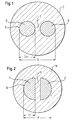
- Figure 1 shows a cross-section of a prior art steel cord A with two circular filaments B separated by a gap E.
- the steel cord A is provided with a coating C.
- the largest dimension of said steel cord A is indicated at D.
- the thickness of said coating C is determined by said largest dimension D.
- the steel cord A is shown enlarged with a scale of approximately 10:1, the filaments B having a diameter of 0.30 mm (a radius of 0.15 mm) and the coating C having a thickness of 1.10 mm. It is obvious that said coating C is unnecessarily thick at the upper and lower side as shown in Figure 1.
- FIG. 2 shows a cross-section of a steel cord 10 in accordance with the invention.
- Said steel cord 10 comprises two filaments 11, 12 which are approximately semi-circular and is provided with a coating 18.
- the filaments 11, 12 are separated by a gap 16.
- the cross-sectional area of said filaments 11, 1 2 is identical to that of the prior art filaments B.
- the largest dimension is indicated at d.
- the steel cord 10 is shown enlarged with scale of 10:1.
- a comparision of Figures 1 and 2 clearly shows that the steel cord 10 in accordance with the invention features a reduced largest dimension d. Accordingly, thickness of the coating 18 may be reduced.
- the gap E or 16, respectively is filled with the coating. Direct contact between the filaments and corrosion thereof is avoided.
- the filaments 11, 12 are semi-circular. Their respective radius may be calculated as follows:
- the absolute change ⁇ with r 1 0.15 mm equals to 0.177 mm.
- the relative change ⁇ /D equals to 0.1609 or a reduction of about 16%. Accordingly, the thickness of the coating may be reduced, too.
- a 1 1 4 T 2 ⁇ ⁇ ⁇ 0.325 ⁇ ⁇ ⁇ 0.9503 mm 2
- a 2 1 4 t 2 ⁇ ⁇ ⁇ 0.169 ⁇ ⁇ ⁇ 0.5320 mm 2
- the steel cord 10 in accordance with the invention allows for a significant reduction in coating thickness.
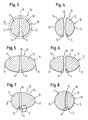
- Figures 3 to 11 show cross-sections of nine different embodiments of a steel cord 10 in accordance with the invention.
- the steel cord 10 comprises two filaments 11, 12, each featuring an outer surface 13 and a contact surface 14.
- the contact surfaces 14 are arranged adjacent to each other so that the outer surfaces 13 provide a smooth outer contour 15 of the steel cord 10.
- the contact surfaces 14 are separated by the gap 16.
- Figures 3 and 4 show a steel cord 10 comprising two substantially semi-circular filaments 11, 12.
- the contact surfaces 14 are configured flat.
- Figure 4 shows filaments 11, 12 with contact surfaces 14 which are slightly curved. It should be noted that curvature of the contact surfaces 14 is exaggerated in the figures for better understanding.
- Figures 5 and 6 show a steel cord comprising filaments 11, 12 which are configured semi-elliptical. Again, the contact surfaces 14 may be flat or slightly curved.
- Figures 3 to 6 show different embodiments of a steel cord 10 the filaments 11, 12 of which feature the same cross-sectional area and cross-section. It is, however, possible to combine filaments 11, 12 of different cross-sections and cross-sectional areas as shown in Figures 7 and 8.
- Figure 7 depicts schematically a semi-circular filament 11 together with a semi-elliptical filament 12.
- Figure 8 shows a filament 11 configured slightly bigger than a semi-circle.
- Corresponding filament 12, accordingly, is configured smaller than a semi-circle.
- the gap 16 is formed by curved contact surfaces 14 arranged in parallel.
- the outer surface 13 is configured arcuate, especially semi-circular or semi-elliptical. It is possible to use a polygonal outer surface 13, too. It is, however, important that the outer contour 1 5 formed by the two outer surfaces 13 be smooth.
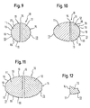
- Figures 9 to 11 show steel cords 10 comprising one or two filaments 11, 12 with a polygonal outer surface 13. Said steel cords 10 do still feature a smooth outer contour 15.
- Figure 9 shows an embodiment with two filaments 11, 12 featuring the same cross-section.
- the outer contour comprises six sides 1 9.
- Figure 10 shows a combination of a semi-elliptical filament 11 and a polygonal filament 12.
- the outer contour 13 of filament 12 comprises seven sides.
- Figure 11 shows two filaments 11, 12 which are basically semi-elliptical, but provided with a polygonal outer surface 13. Both filaments 11, 12 feature seven sides.
- the outer surface 13 of filaments 11, 12 features at least three sides. Otherwise, the steel cord 10 would feature a nearly rectangular outer contour 15 which would not allow the desired reduction in rubber coating thickness.
- Figure 12 shows an enlarged view of detail X in Figure 7.
- the transition between the contact surface 14 and the outer surface 13 features a radius 17. Said radius 17 ensures that no sharp edges are present which might damage the rubber coating during use.
- the above described filaments are wound together according to a winding pitch comprised between 5 mm and 30 mm.
- Figure 1 3 shows a partial cross-section of a tyre 20 comprising a tread member 21, at least a carcass ply 22 and two side walls 23 provided with beads 24 to which the extremities of the carcass ply are associated.
- Each bead portion 24 comprises a reinforcing bead core 50 provided, in a radially external position, with a filler 60.
- Arranged between the tread member 21 and the carcass ply 22 are at least two belts 25, 26.
- Said belts 25, 26 comprise steel cords 10 as described above, parallel to each other in each belt and crossed with the cords of the adjacent belt.
- the tread member 21 comprises a base 27 and a cap 28, the base 27 being provided with shoulders 29 extending up to the tread member surface.
- a groove 30 Arranged between the right-hand shoulder 29 and the cap 28 is a groove 30.
- Profile blocks 31, 32 of the base 27 and the cap 28 are obtained by grooves 33.
- the steel cords 10 Due to the reduction of the largest dimension of the steel cords 10 the thickness of their rubber coating 18 may be reduced. Therefore, the steel cords 10 may be arranged closer to each other in the belts 25, 26. At the same time, the radial dimension of belts 25, 26 may be reduced, so that the distance between the tread member 21 and the carcass ply 22 may be reduced, too. As alternative additional safety means may be inserted.
- the steel cord 10 in accordance with the invention allows a significant reduction of the largest dimension. At the same time, a smooth outer contour 15 of the steel cord 10 is provided. Consequently, the thickness of the coating 18 may be considerably reduced, leading to significant cost savings. Additionally, weight, stiffness and handling of a tyre 20 provided with a steel cord 10 in accordance with the invention may be improved.
Landscapes
- Ropes Or Cables (AREA)
- Tires In General (AREA)
- Organic Low-Molecular-Weight Compounds And Preparation Thereof (AREA)
Abstract
Description
- In its first aspect, the present invention relates to a steel cord, especially for reinforcing rubber articles, comprising two filaments combined in order to form said steel cord. A second aspect of the present invention relates to a method of producing such a steel cord. In a third aspect, the present invention relates to a pneumatic tyre comprising a tread member, a carcass, two side walls and at least one belt.
- A steel cord of the above mentioned kind is known from US 4,606,392 and used for reinforcing vehicle tyres. Said known steel cord comprises several metal wires having each a substantially rectangular cross-section defining opposite broad and narrow sides. The metal wires in the steel cord contact one another along their broad sides to provide a strand of a substantially rectangular cross-section. Other known steel cords comprise two circular filaments with a diameter of around 0.30 mm. Usually, the steel cord is provided with a rubber coating prior to embedding in the material of a tyre. The known steel cord features a rather rough, uneven outer surface. Consequently, the thickness of the rubber coating applied must be at least 0.4 mm higher than the largest dimension of the steel cords. For example a steel cord comprising two filaments with a diameter of 0.30 mm will require a rubber coating with a thickness of 1.10 mm.
- Accordingly, the known steel cord requires a rather thick coating and is quite heavy.
- A steel cord which comprises two filaments is disclosed in JP 63-85190 A. Each of the filaments has an elliptical cross-section and a continuous surface.
- In addition, US 3,018,610 discloses a cord which comprises two filaments made of plastic material. The filaments have a flat contact surface and a semi-circular outer surface. The transition between the contact surface and the outer surface comprises a radius. The cross-section of the filaments is identical. The cord is produced by combining the filaments and subsequently pulling them through a profiling plate which has a window of appropriate size.
- It is an object of the invention to provide a steel cord allowing a reduction in rubber coating thickness. It is another object of the invention to provide a method of producing such a steel cord. A third object of the invention is to enhance tyre properties by using relatively small and lightweight steel cords.
- Said objects are achieved by a steel cord as defined by claim 1, a method as defined by claim 9 and a pneumatic tyre as defined by
claim 11. - Advantageous embodiments of the invention read from the dependent claims.
- The cross-section of the filaments with a contact surface and an arcuate shaped outer surface and the arrangement of the contact surfaces adjacent to each other provide a smooth outer contour of the steel cord. Therefore, the largest dimension of the steel cord may be reduced so that the thickness of the rubber coating may be reduced, too. Reduction of rubber coating thickness leads to a number of advantages. First, the expenses for coating are significantly reduced. Second, the steel cord may be arranged closer to each other, e. g. in the carcass ply or belt of a tyre. Therefore, the weight, stiffness and handling of the tyre may be improved compared to the prior art steel cords.
- It is advantageous to pre-shape the filaments and combine them subsequently in order to form said steel cord. The filaments may be independently pre-shaped from each other. It is possible to obtain any desired form for the contact surface and the outer surface. Additionally, configuration of both the contact surface and the outer surface may be easily assessed. Combining the pre-shaped filaments is to advantage effected with a double twister as disclosed in EP 396 068 B1 issued to the applicant of the present application.
- The contact surface is configured flat or slightly curved. The ideal form of the contact surface is a perfect plane. However, slight deviations from said ideal form are not detrimental.
- The outer surface may be configured semi-circular or semi-elliptical. As alternative, it may be configured polygonal. With said aspect the outer surface to advantage comprises more than three sides. In order to minimize the maximum dimension of the steel cord, a semi-circular outer surface is used. However, even with a semi-elliptical or polygonal outer surface of the filament the steel cord in accordance with the invention still features a smooth outer contour and a reduced maximum dimension. Again, rubber coating thickness may be considerably reduced.
- According to a further aspect of the invention the transition between the contact surface and the outer surface features a radius. None of the filaments is provided with sharp edges which may damage the rubber coating during use. Accordingly, the life time of the steel cord provided with their rubber coating is increased.
- The steel cord uses a gap between the contact surfaces of said two filaments. Said gap may be penetrated by the rubber coating in order to avoid corrosion. Moreover, direct contact between the filaments which is likely to damage a protective coating of the filaments is avoided.
- To advantage, the two filaments feature the same cross-section. It will not be necessary to manufacture and stock different filaments in order to produce the steel cord in accordance with the invention. Additionally, both filaments exhibit the same physical properties.
- In accordance with another embodiment the two filaments may feature different cross-sections. One filament may be configured semi-circular while the other one is configured semi-elliptical. It is possible to create a huge variety of different steel cords which are suited for a number of different applications.
- It is preferred, if the tyre in accordance with the invention comprises two belts which are arranged between the tread member and the carcass. To advantage, the tyre features are radial-ply concept. The use of two belts provides higher safety and reliability, while the radial-ply concept enhances the properties of the tyre.
- The invention will now be detailed by way of example embodiments illustrated schematically in the drawings. Like reference signs have been used for parts identical or identical in function.
- Figure 1
- shows a cross-section of a prior art steel cord provided with a coating;
- Figure 2
- shows a cross-section of a steel cord in accordance with the invention provided with a coating;
- Figures 3 to Figure 11
- show a cross-section of nine different embodiments of a steel cord in accordance with the invention;
- Figure 12
- shows an enlarged view of detail X in Figure 7; and
- Figure 13
- shows a partial cross-section of a tyre.
- Figure 1 shows a cross-section of a prior art steel cord A with two circular filaments B separated by a gap E. The steel cord A is provided with a coating C. The largest dimension of said steel cord A is indicated at D. The thickness of said coating C is determined by said largest dimension D. In Figure 1, the steel cord A is shown enlarged with a scale of approximately 10:1, the filaments B having a diameter of 0.30 mm (a radius of 0.15 mm) and the coating C having a thickness of 1.10 mm. It is obvious that said coating C is unnecessarily thick at the upper and lower side as shown in Figure 1.
- Figure 2 shows a cross-section of a
steel cord 10 in accordance with the invention. Saidsteel cord 10 comprises twofilaments coating 18. Thefilaments gap 16. The cross-sectional area of saidfilaments 11, 1 2 is identical to that of the prior art filaments B. The largest dimension is indicated at d. Again, thesteel cord 10 is shown enlarged with scale of 10:1. A comparision of Figures 1 and 2 clearly shows that thesteel cord 10 in accordance with the invention features a reduced largest dimension d. Accordingly, thickness of thecoating 18 may be reduced. - In both the prior art steel cord A and in the
steel cord 10 in accordance with the invention the gap E or 16, respectively, is filled with the coating. Direct contact between the filaments and corrosion thereof is avoided. - In the embodiment shown, the
filaments - Cross-sectional area of prior art filaments B (radius r1):

- Cross-sectional area of
filaments 11, 12 (radius r2):
- The calculated cross-sectional areas shall be identical:

- Largest dimension D of prior art steel cord A:

- Largest dimension d of
steel cord 10 in accordance with the invention:
- The gap E is approximately equal to the
gap 16. Therefore, the change Δ in the largest dimension d or D, respectively, amounts to:
- The absolute change Δ with r1 = 0.15 mm equals to 0.177 mm. The relative change Δ/D equals to 0.1609 or a reduction of about 16%. Accordingly, the thickness of the coating may be reduced, too.
- The prior art coating thickness T amounts to


- Cross-sectional area A1 of prior art coating C:

- Cross-sectional area A2 of
coating 18 in accordance with the invention:
- Reduction Δ of cross-sectional area:

- Reduction Δ% of cross-sectional area in percent:

- Accordingly, the
steel cord 10 in accordance with the invention allows for a significant reduction in coating thickness. - Figures 3 to 11 show cross-sections of nine different embodiments of a
steel cord 10 in accordance with the invention. As already shown in Figure 2, thesteel cord 10 comprises twofilaments outer surface 13 and acontact surface 14. The contact surfaces 14 are arranged adjacent to each other so that theouter surfaces 13 provide a smoothouter contour 15 of thesteel cord 10. The contact surfaces 14 are separated by thegap 16. - Figures 3 and 4 show a
steel cord 10 comprising two substantiallysemi-circular filaments filaments contact surfaces 14 which are slightly curved. It should be noted that curvature of the contact surfaces 14 is exaggerated in the figures for better understanding. - Figures 5 and 6 show a steel
cord comprising filaments - Figures 3 to 6 show different embodiments of a
steel cord 10 thefilaments filaments semi-circular filament 11 together with asemi-elliptical filament 12. Figure 8 shows afilament 11 configured slightly bigger than a semi-circle. Correspondingfilament 12, accordingly, is configured smaller than a semi-circle. Thegap 16 is formed by curved contact surfaces 14 arranged in parallel. - In all embodiments shown the
outer surface 13 is configured arcuate, especially semi-circular or semi-elliptical. It is possible to use a polygonalouter surface 13, too. It is, however, important that the outer contour 1 5 formed by the twoouter surfaces 13 be smooth. - Figures 9 to 11
show steel cords 10 comprising one or twofilaments outer surface 13. Saidsteel cords 10 do still feature a smoothouter contour 15. Figure 9 shows an embodiment with twofilaments - Figure 10 shows a combination of a
semi-elliptical filament 11 and apolygonal filament 12. Theouter contour 13 offilament 12 comprises seven sides. Figure 11 shows twofilaments outer surface 13. Bothfilaments - It is important that the
outer surface 13 offilaments steel cord 10 would feature a nearly rectangularouter contour 15 which would not allow the desired reduction in rubber coating thickness. - Figure 12 shows an enlarged view of detail X in Figure 7. The transition between the
contact surface 14 and theouter surface 13 features aradius 17. Saidradius 17 ensures that no sharp edges are present which might damage the rubber coating during use. - Preferably, the above described filaments are wound together according to a winding pitch comprised between 5 mm and 30 mm.
- Figure 1 3 shows a partial cross-section of a
tyre 20 comprising atread member 21, at least acarcass ply 22 and twoside walls 23 provided withbeads 24 to which the extremities of the carcass ply are associated. Eachbead portion 24 comprises a reinforcingbead core 50 provided, in a radially external position, with afiller 60. Arranged between thetread member 21 and the carcass ply 22 are at least twobelts belts steel cords 10 as described above, parallel to each other in each belt and crossed with the cords of the adjacent belt. - In the embodiment shown, the
tread member 21 comprises abase 27 and acap 28, thebase 27 being provided withshoulders 29 extending up to the tread member surface. Arranged between the right-hand shoulder 29 and thecap 28 is agroove 30. - Profile blocks 31, 32 of the
base 27 and thecap 28 are obtained bygrooves 33. - Due to the reduction of the largest dimension of the
steel cords 10 the thickness of theirrubber coating 18 may be reduced. Therefore, thesteel cords 10 may be arranged closer to each other in thebelts belts tread member 21 and the carcass ply 22 may be reduced, too. As alternative additional safety means may be inserted. - The
steel cord 10 in accordance with the invention allows a significant reduction of the largest dimension. At the same time, a smoothouter contour 15 of thesteel cord 10 is provided. Consequently, the thickness of thecoating 18 may be considerably reduced, leading to significant cost savings. Additionally, weight, stiffness and handling of atyre 20 provided with asteel cord 10 in accordance with the invention may be improved.
Claims (11)
- A steel cord, especially for reinforcing rubber articles, comprising:two filaments (11, 12) made of steel and having a pre-shaped cross-section;each of the filaments (11; 12) has a contact surface (14) configured flat or slightly curved and an outer surface (13) configured arcuately shaped;the contact surfaces (14) are arranged adjacent to each other, thereby providing a smooth outer contour (15) of the steel cord (10); andthe contact surfaces (14) are separated by a gap (16).
- The steel cord according to claim 1, characterized in that the outer surface (13) is configured semi-circular or semi-elliptical.
- The steel cord according to claim 1, characterized in that the outer surface (13) is configured polygonal.
- The steel cord according to claim 3, characterized in that the outer surface (13) comprises more than three sides.
- The steel cord according to any of the claims 1 to 4, characterized by a transition between the contact surface (14) and the outer surface (13) which defines a radius (17).
- The steel cord according to any of the claims 1 to 5, characterized in that the two filaments (11, 12) have the same cross-section.
- The steel cord according to any of the claims 1 to 5, characterized in that the two filaments (11, 12) have different cross-sections.
- The steel cord according to any of the claims 1 to 7, characterized in that the two filaments (11, 12) are embedded in a coating (18) such that the gap (16) is filled with the coating (18).
- A method for producing a steel cord (10) according to any of claims 1 to 8, characterized in that the two filaments (11, 12) are at first pre-shaped and subsequently combined in order to form the steel cord (10).
- The method according to claim 9, characterized in that the two filaments (11, 12) are embedded in a coating (18), thereby filling the gap (16) with the coating (18).
- A pneumatic tyre comprising:a tread member (21);a carcass ply (22);two side walls (23); andat least one belt (25; 26),characterized in that the carcass ply (22) or the belt (25; 26) include a steel cord (10) according to any of claims 1 to 8.
Priority Applications (1)
| Application Number | Priority Date | Filing Date | Title |
|---|---|---|---|
| EP01986730A EP1325189B1 (en) | 2000-10-12 | 2001-10-11 | Steel cord and method for producing a steel cord |
Applications Claiming Priority (4)
| Application Number | Priority Date | Filing Date | Title |
|---|---|---|---|
| EP00122184A EP1197595A1 (en) | 2000-10-12 | 2000-10-12 | Steel cord and method for producing a steel cord |
| EP00122184 | 2000-10-12 | ||
| PCT/EP2001/011795 WO2002031257A1 (en) | 2000-10-12 | 2001-10-11 | Steel cord and method for producing a steel cord |
| EP01986730A EP1325189B1 (en) | 2000-10-12 | 2001-10-11 | Steel cord and method for producing a steel cord |
Publications (2)
| Publication Number | Publication Date |
|---|---|
| EP1325189A1 EP1325189A1 (en) | 2003-07-09 |
| EP1325189B1 true EP1325189B1 (en) | 2006-08-09 |
Family
ID=8170068
Family Applications (2)
| Application Number | Title | Priority Date | Filing Date |
|---|---|---|---|
| EP00122184A Withdrawn EP1197595A1 (en) | 2000-10-12 | 2000-10-12 | Steel cord and method for producing a steel cord |
| EP01986730A Expired - Lifetime EP1325189B1 (en) | 2000-10-12 | 2001-10-11 | Steel cord and method for producing a steel cord |
Family Applications Before (1)
| Application Number | Title | Priority Date | Filing Date |
|---|---|---|---|
| EP00122184A Withdrawn EP1197595A1 (en) | 2000-10-12 | 2000-10-12 | Steel cord and method for producing a steel cord |
Country Status (8)
| Country | Link |
|---|---|
| US (1) | US7188653B2 (en) |
| EP (2) | EP1197595A1 (en) |
| AT (1) | ATE335876T1 (en) |
| AU (1) | AU2002220619A1 (en) |
| BR (1) | BR0114582A (en) |
| DE (1) | DE60122185T2 (en) |
| ES (1) | ES2269487T3 (en) |
| WO (1) | WO2002031257A1 (en) |
Families Citing this family (8)
| Publication number | Priority date | Publication date | Assignee | Title |
|---|---|---|---|---|
| CN101541564B (en) * | 2006-11-22 | 2012-03-28 | 倍耐力轮胎股份公司 | Tires with lightweight bead cores |
| US7737358B2 (en) * | 2007-04-12 | 2010-06-15 | Commscope, Inc. Of North Carolina | Data transmission cable pairs and cables and methods for forming the same |
| US20140277397A1 (en) * | 2013-03-12 | 2014-09-18 | DePuy Synthes Products, LLC | Variable porosity intravascular implant and manufacturing method |
| CN105321647B (en) | 2014-07-30 | 2018-02-23 | 厦门钨业股份有限公司 | The preparation method of rare-earth magnet quick cooling alloy and rare-earth magnet |
| KR101647091B1 (en) * | 2014-10-14 | 2016-08-09 | 홍덕산업 주식회사 | Steel Cord for Reinforcement of a Tire |
| TR201709160T1 (en) * | 2016-07-01 | 2017-08-21 | Kordsa Teknik Tekstil As | A NEW BIELASTIC CARBON FIBER CORD AS A SUPERIOR SUPPORT |
| EP3478513B1 (en) * | 2016-07-01 | 2020-08-05 | Kordsa Teknik Tekstil Anonim Sirketi | A novel bielastic aramid tire cord as carcass reinforcement |
| WO2018004485A1 (en) * | 2016-07-01 | 2018-01-04 | Kordsa Teknik Tekstil Anonim Sirketi | Novel bielastic aramid tire cord as cap ply |
Family Cites Families (17)
| Publication number | Priority date | Publication date | Assignee | Title |
|---|---|---|---|---|
| US2464186A (en) * | 1945-11-15 | 1949-03-08 | William S Gilpin | Welding wire |
| US2905919A (en) * | 1956-01-17 | 1959-09-22 | British Insulated Callenders | Electric heating cables |
| US3018610A (en) * | 1958-04-29 | 1962-01-30 | Kleinekathofer Felix | Method of manufacturing filamentary structures |
| US3252569A (en) * | 1963-01-29 | 1966-05-24 | Plasti Clad Metal Products Inc | Plastic coated laminated nail |
| GB1424672A (en) * | 1972-04-25 | 1976-02-11 | Gkn Somerset Wire Ltd | Wire strand |
| CA1158816A (en) * | 1980-06-06 | 1983-12-20 | Kazuo Okamoto | Conductive composite filaments and methods for producing said composite filaments |
| DE3317712C2 (en) * | 1983-05-16 | 1986-10-30 | Akzo Gmbh, 5600 Wuppertal | Reinforcement cord for reinforcing elastomeric products |
| JPH0665790B2 (en) * | 1986-09-19 | 1994-08-24 | 金井 宏之 | Steel code |
| JPH0672370B2 (en) * | 1989-02-27 | 1994-09-14 | 住友ゴム工業株式会社 | Steel cord |
| EP0421944A3 (en) * | 1989-08-31 | 1992-06-17 | Tanaka Kikinzoku Kogyo K.K. | Composite carbon fibre and process for preparing same |
| JPH03213402A (en) * | 1990-01-16 | 1991-09-18 | Bridgestone Corp | Tire reinforcing cord |
| JPH04281081A (en) * | 1991-03-06 | 1992-10-06 | Bridgestone Corp | Metallic cord for reinforcing rubber and tire using the same |
| JPH05124402A (en) * | 1991-11-05 | 1993-05-21 | Yokohama Rubber Co Ltd:The | Pneumatic radial tires |
| DE19709884A1 (en) * | 1997-03-11 | 1998-09-17 | Continental Ag | Economical reinforcing steel cord for belt plies and carcasses of vehicular tyres |
| KR100629813B1 (en) * | 1999-06-08 | 2006-09-29 | 도레이 가부시끼가이샤 | Soft Stretch Yarns and Process for the Preparation Thereof |
| EP1118397A1 (en) * | 2000-01-19 | 2001-07-25 | N.V. Bekaert S.A. | A deformed metal composite wire |
| US6465094B1 (en) * | 2000-09-21 | 2002-10-15 | Fiber Innovation Technology, Inc. | Composite fiber construction |
-
2000
- 2000-10-12 EP EP00122184A patent/EP1197595A1/en not_active Withdrawn
-
2001
- 2001-10-11 DE DE60122185T patent/DE60122185T2/en not_active Expired - Fee Related
- 2001-10-11 BR BR0114582-7A patent/BR0114582A/en not_active Application Discontinuation
- 2001-10-11 EP EP01986730A patent/EP1325189B1/en not_active Expired - Lifetime
- 2001-10-11 AT AT01986730T patent/ATE335876T1/en not_active IP Right Cessation
- 2001-10-11 WO PCT/EP2001/011795 patent/WO2002031257A1/en not_active Ceased
- 2001-10-11 ES ES01986730T patent/ES2269487T3/en not_active Expired - Lifetime
- 2001-10-11 AU AU2002220619A patent/AU2002220619A1/en not_active Abandoned
- 2001-10-11 US US10/398,367 patent/US7188653B2/en not_active Expired - Fee Related
Also Published As
| Publication number | Publication date |
|---|---|
| EP1197595A1 (en) | 2002-04-17 |
| AU2002220619A1 (en) | 2002-04-22 |
| EP1325189A1 (en) | 2003-07-09 |
| DE60122185T2 (en) | 2007-07-05 |
| WO2002031257A1 (en) | 2002-04-18 |
| DE60122185D1 (en) | 2006-09-21 |
| US7188653B2 (en) | 2007-03-13 |
| ES2269487T3 (en) | 2007-04-01 |
| BR0114582A (en) | 2004-01-20 |
| ATE335876T1 (en) | 2006-09-15 |
| US20050098253A1 (en) | 2005-05-12 |
Similar Documents
| Publication | Publication Date | Title |
|---|---|---|
| EP1712376B1 (en) | Pneumatic tyre | |
| CN102365180B (en) | Tyre for heavy vehicles comprising a layer of peripheral reinforcement elements | |
| US5295346A (en) | Metal cords for rubber reinforcement and tires using the same | |
| EP0834613B1 (en) | Rubber article reinforcing steel cord and pneumatic tire | |
| US8117818B2 (en) | Steel cord, composite of rubber and steel cord, and tire | |
| US5223060A (en) | Pneumatic radial tire including steel cords of flat oblong cross-sectional configuration | |
| US7404425B2 (en) | Belt package for super single truck tires | |
| EP1041194B1 (en) | Steel cord, method of manufacturing same, and pneumatic tire | |
| JP4204318B2 (en) | Reinforced tire | |
| EP0385666B1 (en) | Pneumatic radial tire | |
| US7188653B2 (en) | Steel cord and method for producing a steel cord | |
| EP1760190A1 (en) | Steel cord for reinforcing rubber article, and pneumatic tire | |
| EP0916521A3 (en) | Pneumatic tire for passenger cars | |
| US20010013385A1 (en) | Pneumatic tire | |
| JP4508546B2 (en) | Steel cords and tires for rubber article reinforcement | |
| JPH044163B2 (en) | ||
| EP1001074B1 (en) | Steel cords for the reinforcement of rubber articles and pneumatic tires | |
| JPH09175112A (en) | Steel cord for reinforcing rubber articles and pneumatic tires | |
| US8499808B2 (en) | Vehicle tire | |
| JP3244780B2 (en) | Pneumatic radial tire | |
| JP4443731B2 (en) | Metal wire and pneumatic tire using the same | |
| JPH0340883A (en) | Pneumatic radial tire | |
| EP0366475A2 (en) | Pneumatic radial tyre | |
| JP4915286B2 (en) | Steel cord for rubber reinforcement and pneumatic radial tire using the same | |
| US20090120549A1 (en) | Tires for Two-Wheeled Vehicles |
Legal Events
| Date | Code | Title | Description |
|---|---|---|---|
| PUAI | Public reference made under article 153(3) epc to a published international application that has entered the european phase |
Free format text: ORIGINAL CODE: 0009012 |
|
| 17P | Request for examination filed |
Effective date: 20030328 |
|
| AK | Designated contracting states |
Designated state(s): AT BE CH CY DE DK ES FI FR GB GR IE IT LI LU MC NL PT SE TR |
|
| AX | Request for extension of the european patent |
Extension state: AL LT LV MK RO SI |
|
| 17Q | First examination report despatched |
Effective date: 20050630 |
|
| GRAP | Despatch of communication of intention to grant a patent |
Free format text: ORIGINAL CODE: EPIDOSNIGR1 |
|
| GRAS | Grant fee paid |
Free format text: ORIGINAL CODE: EPIDOSNIGR3 |
|
| GRAA | (expected) grant |
Free format text: ORIGINAL CODE: 0009210 |
|
| AK | Designated contracting states |
Kind code of ref document: B1 Designated state(s): AT BE CH CY DE DK ES FI FR GB GR IE IT LI LU MC NL PT SE TR |
|
| PG25 | Lapsed in a contracting state [announced via postgrant information from national office to epo] |
Ref country code: IT Free format text: LAPSE BECAUSE OF FAILURE TO SUBMIT A TRANSLATION OF THE DESCRIPTION OR TO PAY THE FEE WITHIN THE PRESCRIBED TIME-LIMIT;WARNING: LAPSES OF ITALIAN PATENTS WITH EFFECTIVE DATE BEFORE 2007 MAY HAVE OCCURRED AT ANY TIME BEFORE 2007. THE CORRECT EFFECTIVE DATE MAY BE DIFFERENT FROM THE ONE RECORDED. Effective date: 20060809 Ref country code: FI Free format text: LAPSE BECAUSE OF FAILURE TO SUBMIT A TRANSLATION OF THE DESCRIPTION OR TO PAY THE FEE WITHIN THE PRESCRIBED TIME-LIMIT Effective date: 20060809 Ref country code: CH Free format text: LAPSE BECAUSE OF FAILURE TO SUBMIT A TRANSLATION OF THE DESCRIPTION OR TO PAY THE FEE WITHIN THE PRESCRIBED TIME-LIMIT Effective date: 20060809 Ref country code: LI Free format text: LAPSE BECAUSE OF FAILURE TO SUBMIT A TRANSLATION OF THE DESCRIPTION OR TO PAY THE FEE WITHIN THE PRESCRIBED TIME-LIMIT Effective date: 20060809 Ref country code: NL Free format text: LAPSE BECAUSE OF FAILURE TO SUBMIT A TRANSLATION OF THE DESCRIPTION OR TO PAY THE FEE WITHIN THE PRESCRIBED TIME-LIMIT Effective date: 20060809 Ref country code: AT Free format text: LAPSE BECAUSE OF FAILURE TO SUBMIT A TRANSLATION OF THE DESCRIPTION OR TO PAY THE FEE WITHIN THE PRESCRIBED TIME-LIMIT Effective date: 20060809 |
|
| REG | Reference to a national code |
Ref country code: GB Ref legal event code: FG4D |
|
| REG | Reference to a national code |
Ref country code: CH Ref legal event code: EP |
|
| REG | Reference to a national code |
Ref country code: IE Ref legal event code: FG4D |
|
| REF | Corresponds to: |
Ref document number: 60122185 Country of ref document: DE Date of ref document: 20060921 Kind code of ref document: P |
|
| PG25 | Lapsed in a contracting state [announced via postgrant information from national office to epo] |
Ref country code: IE Free format text: LAPSE BECAUSE OF NON-PAYMENT OF DUE FEES Effective date: 20061011 |
|
| PG25 | Lapsed in a contracting state [announced via postgrant information from national office to epo] |
Ref country code: MC Free format text: LAPSE BECAUSE OF NON-PAYMENT OF DUE FEES Effective date: 20061031 |
|
| PG25 | Lapsed in a contracting state [announced via postgrant information from national office to epo] |
Ref country code: SE Free format text: LAPSE BECAUSE OF FAILURE TO SUBMIT A TRANSLATION OF THE DESCRIPTION OR TO PAY THE FEE WITHIN THE PRESCRIBED TIME-LIMIT Effective date: 20061109 Ref country code: DK Free format text: LAPSE BECAUSE OF FAILURE TO SUBMIT A TRANSLATION OF THE DESCRIPTION OR TO PAY THE FEE WITHIN THE PRESCRIBED TIME-LIMIT Effective date: 20061109 |
|
| PG25 | Lapsed in a contracting state [announced via postgrant information from national office to epo] |
Ref country code: PT Free format text: LAPSE BECAUSE OF FAILURE TO SUBMIT A TRANSLATION OF THE DESCRIPTION OR TO PAY THE FEE WITHIN THE PRESCRIBED TIME-LIMIT Effective date: 20070109 |
|
| NLV1 | Nl: lapsed or annulled due to failure to fulfill the requirements of art. 29p and 29m of the patents act | ||
| REG | Reference to a national code |
Ref country code: CH Ref legal event code: PL |
|
| ET | Fr: translation filed | ||
| REG | Reference to a national code |
Ref country code: ES Ref legal event code: FG2A Ref document number: 2269487 Country of ref document: ES Kind code of ref document: T3 |
|
| PLBE | No opposition filed within time limit |
Free format text: ORIGINAL CODE: 0009261 |
|
| STAA | Information on the status of an ep patent application or granted ep patent |
Free format text: STATUS: NO OPPOSITION FILED WITHIN TIME LIMIT |
|
| 26N | No opposition filed |
Effective date: 20070510 |
|
| PG25 | Lapsed in a contracting state [announced via postgrant information from national office to epo] |
Ref country code: GR Free format text: LAPSE BECAUSE OF FAILURE TO SUBMIT A TRANSLATION OF THE DESCRIPTION OR TO PAY THE FEE WITHIN THE PRESCRIBED TIME-LIMIT Effective date: 20061110 |
|
| PG25 | Lapsed in a contracting state [announced via postgrant information from national office to epo] |
Ref country code: LU Free format text: LAPSE BECAUSE OF NON-PAYMENT OF DUE FEES Effective date: 20061011 |
|
| PG25 | Lapsed in a contracting state [announced via postgrant information from national office to epo] |
Ref country code: CY Free format text: LAPSE BECAUSE OF FAILURE TO SUBMIT A TRANSLATION OF THE DESCRIPTION OR TO PAY THE FEE WITHIN THE PRESCRIBED TIME-LIMIT Effective date: 20060809 |
|
| PGFP | Annual fee paid to national office [announced via postgrant information from national office to epo] |
Ref country code: DE Payment date: 20081031 Year of fee payment: 8 Ref country code: TR Payment date: 20081006 Year of fee payment: 8 |
|
| PGFP | Annual fee paid to national office [announced via postgrant information from national office to epo] |
Ref country code: ES Payment date: 20081027 Year of fee payment: 8 |
|
| PGFP | Annual fee paid to national office [announced via postgrant information from national office to epo] |
Ref country code: IT Payment date: 20081027 Year of fee payment: 8 Ref country code: BE Payment date: 20081024 Year of fee payment: 8 |
|
| PGFP | Annual fee paid to national office [announced via postgrant information from national office to epo] |
Ref country code: FR Payment date: 20081021 Year of fee payment: 8 |
|
| PGFP | Annual fee paid to national office [announced via postgrant information from national office to epo] |
Ref country code: GB Payment date: 20081024 Year of fee payment: 8 |
|
| BERE | Be: lapsed |
Owner name: *DRAHTCORD SAAR G.M.B.H. & CO. K.G. Effective date: 20091031 |
|
| REG | Reference to a national code |
Ref country code: FR Ref legal event code: ST Effective date: 20100630 |
|
| PG25 | Lapsed in a contracting state [announced via postgrant information from national office to epo] |
Ref country code: FR Free format text: LAPSE BECAUSE OF NON-PAYMENT OF DUE FEES Effective date: 20091102 Ref country code: DE Free format text: LAPSE BECAUSE OF NON-PAYMENT OF DUE FEES Effective date: 20100501 |
|
| PG25 | Lapsed in a contracting state [announced via postgrant information from national office to epo] |
Ref country code: BE Free format text: LAPSE BECAUSE OF NON-PAYMENT OF DUE FEES Effective date: 20091031 |
|
| PG25 | Lapsed in a contracting state [announced via postgrant information from national office to epo] |
Ref country code: GB Free format text: LAPSE BECAUSE OF NON-PAYMENT OF DUE FEES Effective date: 20091011 |
|
| REG | Reference to a national code |
Ref country code: ES Ref legal event code: FD2A Effective date: 20110323 |
|
| PG25 | Lapsed in a contracting state [announced via postgrant information from national office to epo] |
Ref country code: IT Free format text: LAPSE BECAUSE OF NON-PAYMENT OF DUE FEES Effective date: 20091011 |
|
| PG25 | Lapsed in a contracting state [announced via postgrant information from national office to epo] |
Ref country code: ES Free format text: LAPSE BECAUSE OF NON-PAYMENT OF DUE FEES Effective date: 20110310 |
|
| PG25 | Lapsed in a contracting state [announced via postgrant information from national office to epo] |
Ref country code: ES Free format text: LAPSE BECAUSE OF NON-PAYMENT OF DUE FEES Effective date: 20091012 |
|
| PG25 | Lapsed in a contracting state [announced via postgrant information from national office to epo] |
Ref country code: TR Free format text: LAPSE BECAUSE OF NON-PAYMENT OF DUE FEES Effective date: 20091011 |