EP1324626A2 - Control system and method for a wireless communications terminal - Google Patents
Control system and method for a wireless communications terminal Download PDFInfo
- Publication number
- EP1324626A2 EP1324626A2 EP02028677A EP02028677A EP1324626A2 EP 1324626 A2 EP1324626 A2 EP 1324626A2 EP 02028677 A EP02028677 A EP 02028677A EP 02028677 A EP02028677 A EP 02028677A EP 1324626 A2 EP1324626 A2 EP 1324626A2
- Authority
- EP
- European Patent Office
- Prior art keywords
- function state
- wireless communications
- terminal
- communications terminal
- function
- Prior art date
- Legal status (The legal status is an assumption and is not a legal conclusion. Google has not performed a legal analysis and makes no representation as to the accuracy of the status listed.)
- Ceased
Links
Images




Classifications
-
- H—ELECTRICITY
- H04—ELECTRIC COMMUNICATION TECHNIQUE
- H04W—WIRELESS COMMUNICATION NETWORKS
- H04W8/00—Network data management
- H04W8/22—Processing or transfer of terminal data, e.g. status or physical capabilities
- H04W8/24—Transfer of terminal data
- H04W8/245—Transfer of terminal data from a network towards a terminal
Definitions
- the present invention relates to a control system for a wireless communications terminal used in a wireless communications system, and more specifically, to a control system for a wireless communications terminal controlling function states of the wireless communication terminal by using a terminal control device.
- a wireless communications terminal such as a mobile phone and a PHS (Personal Handy phone System) terminal has spread so rapidly that it is now possible to have a conversation over a telephone or communicate with each other by using such wireless communications terminal at any time and any place.
- PHS Personal Handy phone System
- Such a desirable advantage of the wireless communications terminal capable of communicating at any time and any place can be undesirable under some circumstances. For example, it is often undesirable for a school lesson to be disturbed by a student's mobile phone ringing in the classroom.
- the wireless communications terminal which supports various functions, is structured so as to store, for example, information about whether each function is permitted or not, and/or parameters to be used when executing each function, such that the values of the parameters can be changed from outside of the terminal.
- information stored in the wireless communications terminal is hereinafter referred to as a "function state".
- the function state includes information whether calls can be made or received, or information about a type and a sound volume of a ring tone for a received call or mail message, and the like.
- the wireless communications terminal is typically structured so as to enable the function state to be changed by using input keys or the like, thereby allowing a user of the terminal to change the terminal's function state based on the circumstances where the terminal is used.
- the functions of the wireless communications terminal can be restricted within a certain range based on a setting inputted by the user.
- Japanese Patent Laid-Open Publication No. H10-243454 discloses a system for controlling a function state of a wireless communications terminal based on a method other than using a setting inputted by a user.
- a terminal control device is placed in an area where a function state of a wireless communications terminal is to be changed.
- the device transmits a control signal for changing the function state of the terminal, thereby enabling the terminal to change its function state based on the control signal transmitted therefrom.
- the above-described system has a problem that function states of all wireless communications terminals that have received the control signal will be uniformly changed into the same state, thereby restricting the functions of even those wireless communications terminals whose function states are not to be changed. Furthermore, the terminal control device cannot check a wireless communications terminal has actually changed its function state, which makes it impossible for the device to manage the function state of the terminal based on the current function state thereof.
- an object of the present invention is to provide a control system for a wireless communications terminal that can change a function state of a specific wireless communications terminal and allows a terminal control device to check that the wireless communications terminal has actually changed its function state.
- the present invention has the following features to attain the object mentioned above.
- a first aspect of the present invention is directed to a control system for at least one wireless communications terminal for controlling a function of the at least one wireless communications terminal, including: a terminal control device; and the at least one wireless communications terminal, the terminal control device including: a control data generation section for generating control data including control target information to specify a terminal of the at least one wireless communications terminal to be controlled, and function state change information about a change made in a function state of the terminal; and a transmitting section for transmitting the control data generated by the control data generation section to the at least one wireless communications terminal, and each of the at least one wireless communications terminal including: a function state storing section for storing the function state of the wireless communications terminal; a receiving section for receiving the control data transmitted from the terminal control device; an extraction section for extracting the control target information and the function state change information from the control data received by the receiving section; a determination section for determining, based on the control target information extracted by the extraction section, whether the function state stored in the function state storing section is to be changed or not; and a change
- the wireless communications terminal stores its own function state, and the terminal control device transmits, to the wireless communications terminal, the control data including the control target information and the function state change information.
- the wireless communications terminal determines, based on the received control target information, whether the function state is to be changed or not, and changes the stored function state in accordance with the determination result. Thus, it is possible to change a function state of a specific wireless communications terminal.
- each of the at least one wireless communications terminal further includes an owner information storing section for storing owner information of the wireless communications terminal, and the determination section determines, based on the control target information extracted by the extraction section and the owner information stored in the owner information storing section, whether the function state stored in the function state storing section is to be changed or not.
- the wireless communications terminal stores its own owner information, and determines whether the function state is to be changed or not based on the received control target information and owner information.
- the wireless communications terminal stores its own owner information, and determines whether the function state is to be changed or not based on the received control target information and owner information.
- each of the at least one wireless communications terminal further includes a response transmitting section for transmitting, to the terminal control device, a response which indicates whether the function state stored in the function state storing section has been changed or not, the response including identification information of the wireless communications terminal
- the terminal control device further includes: a response receiving section for receiving the response transmitted from the at least one wireless communications terminal; a process history storing section for storing the response received by the response receiving section as a process history; and a management section for changing, based on the process history stored in the process history storing section, a content of the control data to be generated by the control data generation section.
- the wireless communications terminal transmits the response which indicates whether the function state has been changed or not, the response including its own identification information.
- the terminal control device can check that the wireless communications terminal has changed its function state, thereby enabling the function state to be changed effectively.
- the function state change information includes function specification information including a value to be set in the terminal to be controlled and time specification information specifying a period of time during which the value included in the function specification information of the terminal is effective, and the change section changes, only within the period of time specified by the time specification information, the function state stored in the function state storing section into the value included in the function specification information.
- the wireless communications terminal receives the time specification information, and changes the stored function state only within the specified time. Thus, it is possible to temporarily change the function of the wireless communications terminal by using the terminal control device.
- a fifth aspect of the present invention is directed to a terminal control device controlling a function of at least one wireless communications terminal, including: a control data generation section for generating control data including control target information to specify a terminal of the at least one wireless communications terminal to be controlled and function state change information indicating a change made in a function state of the terminal; and a transmitting section for transmitting, to the wireless communications terminal, the control data generated by the control data generation section.
- the terminal control device in the control system for a wireless communications terminal according to the first aspect.
- a sixth aspect of the present invention is directed to a wireless communications terminal structured so that a function thereof is controllable by a terminal control device, including: a function state storing section for storing the terminal's own function state; a receiving section for receiving, from the terminal control device, control data including control target information to specify a terminal to be controlled and function state change information indicating a change made in the function state; an extraction section for extracting the control target information and the function state change information from the control data received by the receiving section: a determination section for determining, based on the control target information extracted by the extraction section, whether the function state stored in the function state storing section is to be changed or not; and a change section for changing, in accordance with the determination result obtained by the determination section, the function state stored in the function state storing section, based on the function state change information extracted by the extraction section.
- the wireless communications terminal in the control system for a wireless communications terminal according to the first aspect.
- a seventh aspect of the present invention is directed to a control method for at least one wireless communications terminal controlling a function of the at least one wireless communications terminal by using a terminal control device, the method being executed with a function state of each of the at least one wireless communications terminal being stored in the wireless communications terminal, wherein the method includes: a generation step, performed by the terminal control device, of generating control data including control target information to specify a terminal of the at least one wireless communications terminal to be controlled and function state change information indicating a change made in the function state of the terminal; a transmitting step, performed by the terminal control device, of transmitting the generated control data to the wireless communications terminal; a receiving step, performed by the wireless communications terminal, of receiving the transmitted control data: an extraction step.
- each of the at least one wireless communications terminal of extracting the control target information and the function state change information from the received control data; a determination step, performed by each of the at least one wireless communications terminal, of determining whether the stored function state is to be changed or not based on the extracted control target information; and a change step, performed by each of the at least one wireless communications terminal, of changing the stored function state based on the extracted function state change information in accordance with the determination result.
- the wireless communications terminal stores its own function state, and the terminal control device transmits, to the wireless communications terminal, the control data including control target information and function state change information.
- the wireless communications terminal determines, based on the received control target information, whether the function state is to be changed or not, and changes the stored function state in accordance with the determination result. Thus, it is possible to change a function state of a specific wireless communications terminal.
- An eighth aspect of the present invention is directed to a program executed by a wireless communications terminal for enabling control of a function by using a terminal control device, the program being executed with a function state of each of the at least one wireless communications terminal being stored in the wireless communications terminal, including: a receiving step of receiving control data including control target information to specify a terminal to be controlled and function state change information indicating a change made in the function state of the terminal; an extraction step of extracting the control target information and the function state change information from the received control data; a determination step of determining, based on the extracted control target information, whether the stored function state is to be changed or not; and a change step of changing, in accordance with the determination result, the stored function state based on the extracted function state change information.
- the eighth aspect it is possible to provide the program executed, by the wireless communications terminal in the control system for a wireless communications terminal according to the first aspect, for enabling a function control by using the terminal control device.
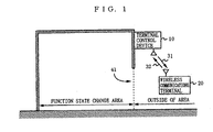
- FIG. 1 is an illustration showing the structure of a control system for a wireless communications terminal according to an embodiment of the present invention.
- the system shown in FIG. 1, including a terminal control device 10 and a wireless communications terminal 20, is characterized by an ability to change function states of the wireless communications terminal 20 found in a function state change area.
- the vertical direction in FIG. 1 corresponds to the direction perpendicular to the ground.
- the term "function state" is used in reference to each of a number of functions supported by the wireless communications terminal.
- the terminal control device 10 and the wireless communications terminal 20 are connected communicably with each other by radio waves. More specifically, the terminal control device 10 and the wireless communications terminal 20 are connected communicably with each other, for example, by using a wireless network such as a wireless local area network (LAN), Bluetooth, infrared communications, a mobile phone, and a PHS terminal.
- the terminal control device 10 is placed around a doorway 41 of an area where the function states of the wireless communications terminal 20 are to be changed (hereinafter referred to as "function state change area"). In FIG. 1, the terminal control device 10 is placed on a wall around a doorway 41 of the function state change area.
- the function state change area is, for example, a hospital, a compartment on a train, a concert hall, a meeting room, and a classroom.
- the terminal control device 10 transmits control data 31 at regular intervals, continuously, or over a specific period of time to the wireless communications terminal 20, which may be taken in or out the function state change area.
- the control data 31 is used to change the function states of the wireless communications terminal 20.
- the control data 31 includes control target information and function state change information.
- the control target information is information for specifying a wireless communications terminal to be (or not to be) controlled.
- the control target information is, for example, information including one or any combination of user's name, users' group name, user's job title, telephone number, mail address, serial number, part number, and generic or proper name of a device, and the like.
- the function state change information is information about a change made in the function states of the wireless communications terminal to be controlled.
- the function state change information includes function specification information and, if necessary, time specification information.
- the function specification information includes a value to be set in the wireless communications terminal as the function states.
- the function specification information includes, for example, a value (ON/OFF value or parameter) to be set in the wireless communications terminal about the following information: power ON, power OFF, phone ring tone OFF, amplifying or lowering the volume of a phone ring tone, phone ring tone ON, amplifying or lowering the volume of a notification sound of an incoming mail, vibration alert ON, vibration alert OFF, wireless signal transmission OFF, wireless signal transmission ON, call reception OFF, call reception ON, data reception OFF, data reception ON, data transmission OFF, and data transmission ON, etc.
- the time specification information is information for specifying a period of time during which the function states are to be changed. Specifically, the time specification information is, for example, one or any arbitrary combination of information about a start time, an end time, and duration.
- the function state change information at least includes function specification information, and may not need to include time specification information.
- the control data 31 transmitted from the terminal control device 10 is determined in various ways.
- the terminal control device 10 may include input means such as input keys or input switches, thereby allowing an administrator of the terminal control device 10 to determine the control data 31.
- the terminal control device 10 may be connected communicably with a management device of a wireless communications system, etc., for receiving the control data 31 therefrom.
- the terminal control device 10 may receive a process end notification 32 about whether the function states of the wireless communications terminal 20 have been changed or not, thereby changing a content of the control data 31 based thereon.
- the wireless communications terminal 20 is, for example, a mobile phone, a PHS terminal, a PDA (Personal Digital Assistant), a personal computer, an audio-video device, etc. Furthermore, the wireless communications terminal 20 may be a headphone or an earphone, etc., communicably connected to each device described above and capable of wireless communications.
- the wireless communication terminal 20 receives, from the terminal control device 10, the control data 31 at a point near the doorway 41 of the function state change area, thereby changing its function states based on the received control data 31 and transmitting the process end notification 32 to the terminal control device 10.
- FIGS. 2A to 2C are illustrations showing other exemplary installations of the terminal control device 10.
- the vertical direction corresponds to the direction perpendicular to the ground as in FIG. 1.
- a terminal control device 10a and a terminal control device 10b are placed on a wall around an entrance 42 and an exit 43 of the function state change area, respectively.
- a terminal control device 10c is placed on a ceiling of the function state change area.
- a terminal control device 10d and a terminal control device 10g are placed on a wall around an entrance 42 and an exit 43 of the function state change area, respectively, and terminal control devices 10e and 10f are each placed on a ceiling of the function state change area.
- the terminal control devices 10a to 10g are placed on the wall or the ceiling.
- the terminal control device 10 may be placed on a floor, or may be deployed in a movable manner.
- the terminal control device 10 may transmit a piece of control data 31 with both control target information and function state change information being included therein, or transmit these two pieces of information separately.
- a base station controlling transmission of the wireless communications terminal 20 may be used as the terminal control device 10, whereby the control data 31 is transmitted by using a wireless communications function originally provided with the wireless communications terminal 20.
- the terminal control device 10 may be installed separately from the base station, whereby the control data 31 is transmitted by using a wireless communications function other than that originally provided with the wireless communications terminal 20.
- the control data 31 may be transmitted by using Bluetooth in the case where the wireless communications terminal 20 is a mobile phone.
- FIG. 3 is a block diagram showing a detailed structure of the terminal control device 10 and the wireless communications terminal 20.
- the terminal control device 10 includes a control data generation section 11, a transmitting section 12, a receiving section 13, a process history storing section 14, and a management section 15.
- the wireless communications terminal 20 includes a receiving section 21, an element extraction section 22, a change determination section 23, an owner information storing section 24, a function state storing section 25, a function state change section 26, and a transmitting section 27.
- the control data generation section 11 generates control data for controlling the function states of the wireless communications terminal 20, and outputs the control data to the transmitting section 12.
- the transmitting section 12 transmits the control data outputted from the control data generation section 11 to the wireless communications terminal 20 by radio waves.
- the control data 31 is transmitted by radio waves from the terminal control device 10 to the wireless communications terminal 20.
- the owner information storing section 24 stores owner information of the wireless communications terminal 20
- the function state storing section 25 stores the function states of the wireless communications terminal 20.
- the receiving section 21 receives the control data 31 transmitted from the terminal control device 10, and outputs the received control data 31 to the element extraction section 22.
- the element extraction section 22 extracts control target information and function state change information from the control data outputted from the receiving section 21, and outputs the extracted information to the change determination section 23.
- the change determination section 23 determines whether any function state stored in the function state storing section 25 is to be changed or not, based on both the control target information outputted from the element extraction section 22 and the owner information stored in the owner information storing section 24.
- the change determination section 23 When it is determined that no function states are to be changed, the change determination section 23 notifies the transmitting section 27 that no function states are to be changed. In this case, the transmitting section 27 transmits the process end notification 32 which indicates that no function states have been changed, the notification including an identifier of the wireless communications terminal 20.
- the change determination section 23 outputs the function state change information outputted from the element extraction section 22 to the function state change section 26.
- the function state change section 26 selects a function state(s) to be changed, based on the function state change information outputted from the change determination section 23 and the current function states stored in the function state storing section 25, thereby changing the function state(s) selected from among the function states stored in the function state storing section 25, based on the function state change information outputted from the change determination section 23. Then, the function state change section 26 notifies the transmitting section 27 of the change result of the function state(s).
- the transmitting section 27 transmits, by radio waves, the process end notification which indicates the change result of the function state(s) 32, the notification including the identifier of the wireless communications terminal 20, based on the notification from the function state change section 26.
- the process end notification 32 is transmitted by radio waves from the wireless communications terminal 20 to the terminal control device 10.
- the process history storing section 14 stores as a process history the change result of the function state(s) transmitted from the wireless communications terminal 20.
- the receiving section 13 receives the process end notification 32 transmitted from the wireless communications terminal 20, and updates the process history stored in the process history storing section 14 based on the received process end notification 32.
- the management section 15 manages an operation of the control data generation section 11 based on the process history stored in the process history storing section 14. For example, when the process end notification 32 is received from all of the wireless communications terminals 20 whose function state (s) is to be changed, the management section 15 may control the control data generation section 11 to stop transmission of the control data 31.
- the management section 15 may control the control data generation section 11 so as to control only the wireless communications terminal 20 that has transmitted the process end notification 32 indicating that its function state(s) has been changed (that is, the wireless communications terminal 20 whose function state(s) has been changed).
- the management section 15 may identify the wireless communications terminal 20 taken in or out the function state change area based on the process history stored in the process history storing section 14, for example, to check whether each student is present or not in the case where the function state change area is a classroom.
- the wireless communications terminal 20 waits for the control data 31 as well as a wireless signal to come when it is operating. When the wireless signal is received, the wireless communications terminal 20 executes a wireless communications function originally provided therewith.
- the wireless communications terminal 20 may have any type of wireless communications function, and the type thereof does not affect the structure of the present invention. Therefore, the description thereof is hereinafter omitted.
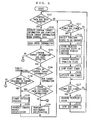
- FIG. 4 is the flowchart illustrating a function state change process performed by the wireless communications terminal 20.
- two timers are used: a start timer for measuring a time to lapse after receiving the control data 31 before beginning to change a function state(s), and an end timer for measuring a time to lapse after changing the function state(s) before restoring it to the original state.
- start timer for measuring a time to lapse after receiving the control data 31 before beginning to change a function state(s
- an end timer for measuring a time to lapse after changing the function state(s) before restoring it to the original state.
- the wireless communications terminal 20 repeatedly performs the following three processes: a process performed when the control data has been received (steps S102 to S110), a process performed when the start timer has timed out (steps S112 to S116), and a process performed when the end timer has timed out (steps S118 to S119). More specifically, the wireless communications terminal 20 determines whether the control data has been received or not (step S101). When it is determined that the control data has been received, the wireless communications terminal 20 performs the process carried out in steps S102 to S110. Then, the wireless communications terminal 20 determines whether the start timer has timed out or not (step S111).
- the wireless communications terminal 20 When it is determined that the start timer has timed out, the wireless communications terminal 20 performs the process carried out in steps S112 to S116. Then, the wireless communications terminal 20 determines whether the end timer has timed out or not (step S117). When it is determined that the end timer has timed out, the wireless communications terminal 20 performs the process carried out in steps S118 to S119. Then, the wireless communications terminal 20 returns to step S101, and repeats the above-described three processes.
- the receiving section 21 receives the control data 31 transmitted from the terminal control device 10 and outputs the received control data to the element extraction section 22.
- the element extraction section 22 extracts both the control target information and the function state change information from the control data outputted from the receiving section 21 and outputs the extracted information to the change determination section 23 (step S102).
- the change determination section 23 reads the owner information of the wireless communications terminal 20 from the owner information storing section 24 (step S103). Then, the change determination section 23 determines whether the control target information has been extracted in step S102 or not (step S104). When it is determined that the control target information has been extracted in step S102, the change determination section 23 proceeds to step S105. Otherwise, the change determination section 23 proceeds to step S110.
- the change determination section 23 checks the type of the control target information extracted in the element extraction section 22 (step S105), that is, checks which one of the information, target information or non-target information, has been included in the control target information.
- the target information is information for specifying a wireless communications terminal whose function state(s) is to be changed
- the non-target information is information for specifying a wireless communications terminal whose function state(s) is not to be changed.
- the change determination section 23 proceeds to step S106 when the control target information is target information, or proceeds to step S107 when the control target information is non-target information.
- the change determination section 23 determines whether an owner of the wireless communications terminal 20 is included in the target information or not, based on the target information and the owner information read in step S103 (step S106).
- the control target information is non-target information
- the change determination section 23 determines whether the owner is excluded from the non-target information or not, based on the non-target information and the owner information read in step S103 (step S107).
- the change determination section 23 proceeds to step S108.
- the function state change section 26 performs a timer setting process (shown in FIG. 5) (step S108). In the timer setting process, values of the start timer and the end timer are set if required. Then, the function state change section 26 notifies the transmitting section 27 of the change result of the function state(s). The transmitting section 27 transmits the process end notification 32 which indicates the change result of the function state(s) to the terminal control device 10, the notification including the identifier of the wireless communications terminal 20, based on the notification from the function state change section 26(step S109).
- step S110 when it is determined that the owner is not included in the target information in step S106, or that the owner is not excluded from the non-target information in step S107, the change determination section 23 proceeds to step S110.
- the change determination section 23 notifies the transmitting section 27 that the function state(s) is not to be changed.
- the transmitting section 27 transmits the process end notification 32 which indicates that the function state(s) has not been changed, the notification including the identifier of the wireless communications terminal 20(step S110).
- the function state change section 26 starts operating.
- the function state change section 26 selects a function state(s) to be changed based on the function specification information extracted in step S201 described further below and the current function states stored in the function state storing section 25 (step S112). More specifically, the function state change section 26 supposes that, in principle, all the function states included in the function specification information are to be changed, and then excludes, from the function states to be changed, any function state whose two values (i.e., one included in the function specification information and another stored in the function state storing section 25) coincide with each other.
- the function state change section 26 reads the value of the selected function state(s) from the function state storing section 25, which is currently stored therein, for saving the read value in another storing section (not shown) (step S113). By saving the current function states as described above, the function states can be restored to the original state when the end timer has timed out. Then, the function state change section 26 changes the value of the selected function state(s), which is currently stored in the function state storing section 25, into the value included in the function specification information (step S114). Then, the function state change section 26 stops the start timer (step S115), and activates the end timer (step S116). The end timer is timed out when a time corresponding to the set value of the timer has lapsed.
- step S118 the process performed when the end timer has timed out (steps S118 to S119) is described.
- the function state change section 26 starts operating.
- the function state change section 26 restores the function states stored in the function state storing section 25 to the original state (step S118). More specifically, the function state change section reads the value stored in another storing section 26 in step S113, and changes the value of the function states stored in the function state storing section 25 into the read value. Then, the function state change section 26 stops the end timer (step S119).
- FIG. 5 is a flowchart illustrating the details of the timer setting process (step S108).
- the function change section 26 operates in the timer setting process.
- the function change section 26 extracts function specification information from the function state change information outputted from the change determination section 23 (step S201). Then, the function state change section 26 determines whether the function specification information has been extracted in step S201 or not (step S202). When it is determined that the function specification information has been extracted in step S201, the function state change section 26 proceeds to step S203. In this case, the function state change section 26 determines whether both the start timer and the end timer have been unset or not (step S203). When it is determined that both the start timer and the end timer have been unset, the function state change section 26 proceeds to step S204.
- step S202 When it is determined in step S202 that the function specification information has not been extracted in step S201, or determined in step S203 that neither the start timer nor the end timer have been unset, the function state change section 26 ends the timer setting process without completing the following processing. Thus, even if the wireless communications terminal 20 repeatedly receives the control data, it is possible to prevent the two timers from having values repeatedly set therein.
- the function state change section 26 extracts, from the function state change information outputted from the change determination section 23, a start time and an end time included in the time specification information (step S204).
- the start time and the end time extracted in step S204 are hereinafter represented as TS and TE, respectively.
- the function state change section 26 determines whether the start time and the end time have been extracted in step S204 (step S205). When it is determined that both the start time and the end time have been extracted in step S205, the function state change section 26 proceeds to step S206. When it is determined that either the start time or the end time has been extracted, the function state change section 26 proceeds to step S215. When neither the start time nor the end time has been extracted, the function state change section 26 proceeds to step S211.
- the function state change section 26 obtains a current time (step S206).
- the obtained current time is hereinafter represented as TC.
- the function state change section 26 compares the start time TS and the end time TE with the current time TC (step S207).
- the function state change section 26 may compare hours and minutes of TS, TE, and TC, or may compare hours, minutes, and seconds thereof.
- TC is smaller than TS (i.e., the current time is earlier than the start time)
- the function state change section 26 proceeds to step S208.
- the function state change section 26 sets the start timer to (TS-TC) and the end timer to (TE-TS) (step S208).
- the function state change section 26 activates the start timer (step S209), and proceeds to step S215.
- the start timer is timed out when time corresponding to the set value of the timer has lapsed.
- the function state change section 26 sets the start timer to 0 (indicating that the start timer will be timed out immediately) and the end timer to (TE-TC) (step S210), and proceeds to step S215.
- TC is equal to or greater than TE (i.e., the current time is later than the end time)
- the function state change section 26 proceeds to step S215 without setting values in the two timers.
- step S206 When it is determined in step S206 that neither the start time nor the end time has been extracted, the function state change section 26 extracts the duration, if any, from the time specification information (step S211).
- the duration extracted in step S211 is hereinafter represented as TX.
- the function state change section 26 determines whether the duration has been extracted in step S211 or not (step S212).
- the function state change section 26 sets the end timer to TX (step S213).
- step S214 sets the start timer to 0 (step S214), and proceeds to step S215.
- step S215 the function state change section 26 stores the function specification information extracted in step S201.
- the function specification information stored in step S215 is used in the process (steps S112 to S116) performed when the start timer has timed out.
- step S205 when it is determined in step S205 that either the start time or the end time has been extracted. it is assumed that the function state change section 26 determines that the format of the time specification information is not correct, and does not set values in the two timers. In this case, however, the function state change section 26 may set values to the two timers based on the extracted time.
- the function state change process may be performed in the wireless communications terminal 20 by preparing a program operated in accordance with the flowcharts shown in FIGS. 4 and 5, and making a CPU (not shown) incorporated in the wireless communications terminal 20 execute the program.
- the program may be preinstalled in the wireless communications terminal 20, or downloaded for use in the wireless communications terminal 20 by using the wireless communications function.
- FIGS. 6A to 6C are illustrations showing exemplary structures of the control data 31 transmitted from the terminal control device 10 to the wireless communications terminal 20.
- the control data 31a shown in FIG. 6A is used in the case of desiring to restrict the function of students' wireless communications terminals (e.g., mobile phones) within the function state change area (in this case, a school classroom) during class.
- a server controlling the function states of a mobile phone is placed, for example, as shown in FIG. 1. Both the server and the wireless communications terminal are capable of short-range wireless communications such as Bluetooth.
- the server is placed on a wall around a doorway 41 of the classroom for transmitting, only when the students are taking lessons, the control data 31a at regular intervals (for example, once every 0.1 seconds) to change a function state(s) of the students' mobile phones, etc.
- the control data 31a includes control target information and function state change information.
- the control target information includes two pieces of non-target information.
- the two pieces of non-target information indicates that the wireless communications terminals of ALL the users who belong to either a TEACHER or a STAFF group are not to be subjected to a function state change.
- two pieces of non-target information indicates that the wireless communications terminal of a user who does not belong to any of the TEACHER and the STAFF groups (e.g., student) is to be subjected to a function state change.
- the function state change information includes four pieces of function specification information, and a start time and an end time as time specification information, thereby indicating that the function states of the wireless communications terminal are to be changed in order to turn a speaker OFF, a vibration alert ON, a telephone signal transmission OFF, and an e-mail transmission OFF from 19:00 to 20:30.
- the function state values of the students' mobile phones are changed temporarily, from 19:00 to 20:30, into values included in the function specification information of the control data 31a by the function state change process (see FIGS. 4 and 5), thereby turning the students' mobile phones "muted, telephone signal transmission OFF, and e-mail transmission OFF" from 19:00 to 20:30.
- the function of the students' mobile phones is temporarily, that is, when they are taking lessons, restricted within a predetermined range.
- a student enters the classroom with his/her mobile phone OFF and turns it ON in the classroom in order to avoid his/her mobile phone being subjected to a function state change.
- a server administrator e.g., teacher
- a server administrator can detect the student whose mobile phone has not been subjected to a function state change by checking the identifiers obtained by the server.
- the control data 31b shown in FIG. 6B is used in the case of desiring to turn the volume of a person's (hereinafter assumed to be "Taro") headphone to the maximum within the function state change area (in this case, Taro's room).
- a control system for a wireless communications terminal using the control data 31b includes a component stereo system as the terminal control device 10 and the headphone as the wireless communications terminal 20.
- both the component stereo system and the headphone are capable of short-range wireless communications such as Bluetooth.
- the component stereo system is placed in Taro's room, and transmits the control data 31b at regular intervals to change the function states of Taro's headphone.
- the control data 31b includes control target information and the function state change information.
- the control target information includes a piece of target information.
- the target information indicates that the wireless communications terminal whose user's name is TARO and group name is HEADPHONE (i.e., Taro's headphone) is subjected to a function state change.
- the function state change information includes a piece of function specification information indicating that the function states of the wireless communications terminal are to be changed to turn the volume of the speaker to MAX (maximum).
- the group name HEADPHONE and the user's name TARO are stored in Taro's headphone as owner information.
- the control data 31c shown in FIG. 6C is used for the wireless communications terminal (here, it is referred to as "PDA-light") that can function as a telephone only when it is in the vicinity of a specific server.
- the PDA-light is assumed to be a device that has a telephone function, but usually sends and receives a text message only in order to provide various services inexpensively.
- a user of the PDA-light moves toward the neighborhood of a nearby server, which is placed in various locations.
- Both the server and the PDA-light are capable of short-range wireless communications such as Bluetooth, and the server transmits the control data 31c at regular intervals for controlling the function states of the PDA-light.
- the control data 31c includes control target information and function state change information.
- the control target information includes a piece of target information.
- the target information indicates ALL users' wireless communications terminals belonging to a PDA-light group (i.e., all PDA-lights) are subjected to a function state change.
- the function state change Information includes a piece of function specification information and duration as time specification information.
- the function specification information and the duration indicate that the function states of the wireless communications terminal are to be changed so that the telephone function turns ON for only 600 seconds.
- a group name PDA-light is stored as owner information in each PDA-light.
- the PDA-light which usually does not function as a telephone, can be used as a telephone for only 600 seconds if it receives the control data 31c in the vicinity of the server.
- the wireless communications terminal stores owner information and function states
- the terminal control device transmits, to the wireless communications terminal, control data including control target information for terminal specification and function state change information indicating a function state(s) of the terminal to be changed.
- the wireless communications terminal determines whether the function state(s) is to be changed or not, based on the stored owner information and the received control target information, and changes the stored function states in accordance with the determination result. Thus, it is possible to change a function state(s) of a specific wireless communications terminal.
- the wireless communications terminal transmits a process end notification which indicates whether its function state(s) has been changed or not, the notification including the terminal's own identifier.
- the terminal control device can check that the wireless communications terminal has changed its function state(s), thereby enabling the function state(s) to be changed effectively.
Landscapes
- Engineering & Computer Science (AREA)
- Databases & Information Systems (AREA)
- Computer Networks & Wireless Communication (AREA)
- Signal Processing (AREA)
- Mobile Radio Communication Systems (AREA)
- Telephone Function (AREA)
- Telephonic Communication Services (AREA)
- Selective Calling Equipment (AREA)
Abstract
Description
Claims (8)
- A control system for at least one wireless communications terminal for controlling a function of the at least one wireless communications terminal, comprising:a terminal control device (10); andthe at least one wireless communications terminal (20),the terminal control device comprising:control data generation means (11) for generating control data including control target information to specify a terminal of the at least one wireless communications terminal to be controlled, and function state change information about a change made in a function state of the terminal; andtransmitting means (12) for transmitting the control data generated by the control data generation means to the at least one wireless communications terminal, andeach of the at least one wireless communications terminal comprising:function state storing means (25) for storing the function state of the wireless communications terminal;receiving means (21) for receiving the control data transmitted from the terminal control device;extraction means (22) for extracting the control target information and the function state change information from the control data received by the receiving means;determination means (23) for determining, based on the control target information extracted by the extraction means, whether the function state stored in the function state storing means is to be changed or not; andchange means (26) for changing, in accordance with a determination result obtained by the determination means, the function state stored in the function state storing means, based on the function state change information extracted by the extraction means.
- The control system according to claim 1, wherein
each of the at least one wireless communications terminal further comprises owner information storing means (24) for storing owner information of the wireless communications terminal, and
the determination means determines, based on the control target information extracted by the extraction means and the owner information stored in the owner information storing means, whether the function state stored in the function state storing means is to be changed or not. - The control system according to claim 2, wherein
each of the at least one wireless communications terminal further comprises response transmitting means (27) for transmitting, to the terminal control device, a response which indicates whether the function state stored in the function state storing means has been changed or not, the response including identification information of the wireless communications terminal, and
the terminal control device further comprises:response receiving means (13) for receiving the response transmitted from the at least one wireless communications terminal;process history storing means (14) for storing the response received by the response receiving means as a process history; andmanagement means (15) for changing, based on the process history stored in the process history storing means, a content of the control data to be generated by the control data generation means. - The control system according to claim 2, wherein
the function state change information includes function specification information including a value to be set in the terminal to be controlled and time specification information specifying a period of time during which the value included in the function specification information of the terminal is effective, and
the change means changes, only within the period of time specified by the time specification information, the function state stored in the function state storing means into the value included in the function specification information. - A terminal control device (10) controlling a function of at least one wireless communications terminal, comprising:control data generation means (11) for generating control data including control target information to specify a terminal of the at least one wireless communications terminal to be controlled and function state change information indicating a change made in a function state of the terminal; andtransmitting means (12) for transmitting, to the wireless communications terminal, the control data generated by the control data generation means.
- A wireless communications terminal (20) structured so that a function thereof is controllable by a terminal control device, comprising:function state storing means (25) for storing the terminal's own function state;receiving means (21) for receiving, from the terminal control device, control data including control target information to specify a terminal to be controlled and function state change information indicating a change made in the function state;extraction means (22) for extracting the control target information and the function state change information from the control data received by the receiving means;determination means (23) for determining, based on the control target information extracted by the extraction means, whether the function state stored in the function state storing means is to be changed or not; andchange means (26) for changing, in accordance with the determination result obtained by the determination means, the function state stored in the function state storing means, based on the function state change information extracted by the extraction means.
- A control method for at least one wireless communications terminal controlling a function of the at least one wireless communications terminal by using a terminal control device,
the method being executed with a function state of each of the at least one wireless communications terminal being stored in the wireless communications terminal, wherein the method comprises:a generation step, performed by the terminal control device, of generating control data including control target information to specify a terminal of the at least one wireless communications terminal to be controlled and function state change information indicating a change made in the function state of the terminal;a transmitting step, performed by the terminal control device, of transmitting the generated control data to the wireless communications terminal;a receiving step, performed by the wireless communications terminal, of receiving the transmitted control data;an extraction step, performed by each of the at least one wireless communications terminal, of extracting the control target information and the function state change information from the received control data;a determination step, performed by each of the at least one wireless communications terminal, of determining whether the stored function state is to be changed or not based on the extracted control target information: anda change step, performed by each of the at least one wireless communications terminal, of changing the stored function state based on the extracted function state change information in accordance with the determination result. - A program executed by a wireless communications terminal for enabling control of a function by using a terminal control device,
the program being executed with a function state of each of the at least one wireless communications terminal being stored in the wireless communications terminal, comprising:a receiving step of receiving control data including control target information to specify a terminal to be controlled and function state change information indicating a change made in the function state of the terminal;an extraction step of extracting the control target information and the function state change information from the received control data;a determination step of determining, based on the extracted control target information, whether the stored function state is to be changed or not; anda change step of changing, in accordance with the determination result, the stored function state based on the extracted function state change information.
Applications Claiming Priority (2)
| Application Number | Priority Date | Filing Date | Title |
|---|---|---|---|
| JP2001400121 | 2001-12-28 | ||
| JP2001400121 | 2001-12-28 |
Publications (2)
| Publication Number | Publication Date |
|---|---|
| EP1324626A2 true EP1324626A2 (en) | 2003-07-02 |
| EP1324626A3 EP1324626A3 (en) | 2003-12-17 |
Family
ID=19189572
Family Applications (1)
| Application Number | Title | Priority Date | Filing Date |
|---|---|---|---|
| EP02028677A Ceased EP1324626A3 (en) | 2001-12-28 | 2002-12-20 | Control system and method for a wireless communications terminal |
Country Status (3)
| Country | Link |
|---|---|
| US (1) | US6961579B2 (en) |
| EP (1) | EP1324626A3 (en) |
| CN (1) | CN1307809C (en) |
Cited By (2)
| Publication number | Priority date | Publication date | Assignee | Title |
|---|---|---|---|---|
| WO2005120120A1 (en) * | 2004-06-04 | 2005-12-15 | Matsushita Electric Industrial Co., Ltd. | Mobile terminal device, mobile function limit system, function limit method, and recording medium |
| EP1830588A4 (en) * | 2004-12-22 | 2010-03-17 | Fujitsu Ltd | METHOD FOR CONTROLLING PORTABLE COMMUNICATION EQUIPMENT |
Families Citing this family (36)
| Publication number | Priority date | Publication date | Assignee | Title |
|---|---|---|---|---|
| US7668541B2 (en) | 2003-01-31 | 2010-02-23 | Qualcomm Incorporated | Enhanced techniques for using core based nodes for state transfer |
| US7248885B2 (en) * | 2003-05-09 | 2007-07-24 | Lucent Technologies Inc. | Automatic/timed silencing of mobile phone from a network |
| WO2004109460A2 (en) * | 2003-06-03 | 2004-12-16 | Bart Stanco | Improved personal communication devices for secure communication and locating system |
| KR100541502B1 (en) * | 2003-08-07 | 2006-01-10 | 주식회사 팬택 | Mobile communication terminal control device using location tracking system and its control method |
| JP2005150983A (en) * | 2003-11-12 | 2005-06-09 | Ntt Docomo Inc | Server device |
| US7187950B2 (en) * | 2003-11-14 | 2007-03-06 | Intel Corporation | Command station for mobile radio networks |
| TWI253812B (en) * | 2004-01-09 | 2006-04-21 | Benq Corp | Method of changing the configuration of mobile unit by broadcasting message |
| US7693545B2 (en) | 2004-02-05 | 2010-04-06 | Samsung Electronics Co., Ltd | System and method for controlling functions of mobile communication terminal in a restricted zone |
| US7194273B2 (en) * | 2004-02-12 | 2007-03-20 | Lucent Technologies Inc. | Location based service restrictions for mobile applications |
| CN1319401C (en) * | 2004-02-16 | 2007-05-30 | 明基电通股份有限公司 | How to Change Mobile Unit Settings Using Broadcast Messages |
| FR2870663B1 (en) * | 2004-05-24 | 2006-08-18 | Alcatel Sa | TRANSMISSION OF MANAGEMENT INFORMATION, AFTER SELECTION AND POSSIBLE COMPRESSION WITHIN A RADIO COMMUNICATION NETWORK |
| US20050266857A1 (en) * | 2004-05-27 | 2005-12-01 | Nokia Corporation | Location based execution rights |
| KR100677342B1 (en) * | 2004-07-30 | 2007-02-02 | 엘지전자 주식회사 | Method for setting configuration of mobile terminal |
| US20060063563A1 (en) * | 2004-09-18 | 2006-03-23 | Kaufman Richard D | Cell phone system with automatic ringer/vibrate/silent/operating mode settings based on entering/exiting public areas and theaters |
| US7400891B2 (en) * | 2004-11-10 | 2008-07-15 | At&T Delaware Intellectual Property, Inc. | Methods, systems and computer program products for remotely controlling wireless terminals |
| US20060154674A1 (en) * | 2005-01-11 | 2006-07-13 | Agere Systems Incorporated | Mobile communication device having geographical device setting control and method of operation thereof |
| US20060166678A1 (en) * | 2005-01-26 | 2006-07-27 | Jeyhan Karaoguz | Profile selection and call forwarding based upon wireless terminal GPS location coordinates |
| PL1897332T3 (en) * | 2005-06-23 | 2016-02-29 | Philips Lighting Holding Bv | An apparatus and method of configuring a device in a network |
| US8983468B2 (en) | 2005-12-22 | 2015-03-17 | Qualcomm Incorporated | Communications methods and apparatus using physical attachment point identifiers |
| US9736752B2 (en) | 2005-12-22 | 2017-08-15 | Qualcomm Incorporated | Communications methods and apparatus using physical attachment point identifiers which support dual communications links |
| US8982835B2 (en) | 2005-09-19 | 2015-03-17 | Qualcomm Incorporated | Provision of a move indication to a resource requester |
| US9066344B2 (en) | 2005-09-19 | 2015-06-23 | Qualcomm Incorporated | State synchronization of access routers |
| US9078084B2 (en) | 2005-12-22 | 2015-07-07 | Qualcomm Incorporated | Method and apparatus for end node assisted neighbor discovery |
| US8982778B2 (en) | 2005-09-19 | 2015-03-17 | Qualcomm Incorporated | Packet routing in a wireless communications environment |
| US9083355B2 (en) | 2006-02-24 | 2015-07-14 | Qualcomm Incorporated | Method and apparatus for end node assisted neighbor discovery |
| TW200737906A (en) * | 2006-03-21 | 2007-10-01 | Mitac Int Corp | Operation mode switch system and operation switch mode reminder system |
| US20090252131A1 (en) * | 2006-07-14 | 2009-10-08 | Masashi Itoh | Radio terminal and base station search method by means of radio terminal |
| US7835730B2 (en) * | 2007-01-18 | 2010-11-16 | International Business Machines Corporation | Using RFID and sensored zones to geographically control cellular phone audio profiles |
| US9155008B2 (en) | 2007-03-26 | 2015-10-06 | Qualcomm Incorporated | Apparatus and method of performing a handoff in a communication network |
| US8830818B2 (en) | 2007-06-07 | 2014-09-09 | Qualcomm Incorporated | Forward handover under radio link failure |
| US9094173B2 (en) | 2007-06-25 | 2015-07-28 | Qualcomm Incorporated | Recovery from handoff error due to false detection of handoff completion signal at access terminal |
| US8073438B2 (en) * | 2009-06-03 | 2011-12-06 | Mcnally Christopher | Method and system for disabling a wireless communication device |
| US8615241B2 (en) | 2010-04-09 | 2013-12-24 | Qualcomm Incorporated | Methods and apparatus for facilitating robust forward handover in long term evolution (LTE) communication systems |
| JP5895225B2 (en) * | 2011-08-24 | 2016-03-30 | パナソニックIpマネジメント株式会社 | Device control system, radio control apparatus, and radio control apparatus program |
| TW201322039A (en) * | 2011-11-18 | 2013-06-01 | Hon Hai Prec Ind Co Ltd | Safe management system and safe management method |
| US9325836B2 (en) * | 2014-05-02 | 2016-04-26 | Anthony Cerda | Learning guard system |
Family Cites Families (55)
| Publication number | Priority date | Publication date | Assignee | Title |
|---|---|---|---|---|
| US5778304A (en) * | 1994-03-10 | 1998-07-07 | Motorola, Inc. | Method for providing communication services based on geographic location |
| US5629981A (en) * | 1994-07-29 | 1997-05-13 | Texas Instruments Incorporated | Information management and security system |
| IL119694A0 (en) * | 1996-11-26 | 1997-06-10 | Point Ltd V | A method and device to disable cellular communication |
| JPH10243454A (en) | 1997-02-21 | 1998-09-11 | Toshiba Corp | Wireless communication system and electromagnetic wave notification device |
| US5914671A (en) * | 1997-02-27 | 1999-06-22 | Micron Communications, Inc. | System and method for locating individuals and equipment, airline reservation system, communication system |
| EP0891110A1 (en) * | 1997-07-10 | 1999-01-13 | Alcatel | Method and system for preventing a mobile station from causing disturbance |
| US6025780A (en) * | 1997-07-25 | 2000-02-15 | Checkpoint Systems, Inc. | RFID tags which are virtually activated and/or deactivated and apparatus and methods of using same in an electronic security system |
| JP2965007B2 (en) * | 1997-08-11 | 1999-10-18 | 日本電気株式会社 | Mobile phone system |
| JP3893696B2 (en) * | 1997-10-24 | 2007-03-14 | カシオ計算機株式会社 | Communication terminal device |
| US6995675B2 (en) * | 1998-03-09 | 2006-02-07 | Curkendall Leland D | Method and system for agricultural data collection and management |
| US6792260B1 (en) * | 1998-04-17 | 2004-09-14 | Nec Corporation | Automatic radio wave output limiting system for portable telephone set |
| US6116505A (en) * | 1998-07-21 | 2000-09-12 | Gilbarco Inc. | Fuel transaction system for enabling the purchase of fuel and non-fuel items on a single authorization |
| US6360208B1 (en) * | 1999-02-04 | 2002-03-19 | Intermec Ip Corp. | Method and apparatus for automatic tax verification |
| US6677858B1 (en) * | 1999-02-26 | 2004-01-13 | Reveo, Inc. | Internet-based method of and system for monitoring space-time coordinate information and biophysiological state information collected from an animate object along a course through the space-time continuum |
| EP1041849A1 (en) * | 1999-03-12 | 2000-10-04 | Sony International (Europe) GmbH | Protecting a predetermined area from disturbing usage of mobile terminals |
| JP3334681B2 (en) * | 1999-06-08 | 2002-10-15 | 日本電気株式会社 | Wireless terminal and control method in wireless terminal |
| SE9902137D0 (en) * | 1999-06-08 | 1999-06-08 | Ericsson Telefon Ab L M | A method and a system related to a mobile communication device |
| US20010027439A1 (en) * | 1999-07-16 | 2001-10-04 | Holtzman Henry N. | Method and system for computerized form completion |
| WO2001016915A1 (en) * | 1999-09-02 | 2001-03-08 | Idmicro, Inc. | Airport parking communication system |
| US6529880B1 (en) * | 1999-12-01 | 2003-03-04 | Intermec Ip Corp. | Automatic payment system for a plurality of remote merchants |
| US6354493B1 (en) * | 1999-12-23 | 2002-03-12 | Sensormatic Electronics Corporation | System and method for finding a specific RFID tagged article located in a plurality of RFID tagged articles |
| JP3690953B2 (en) * | 2000-02-23 | 2005-08-31 | 松下電器産業株式会社 | Delivery article handling system and delivery article handling method |
| WO2001063440A2 (en) * | 2000-02-23 | 2001-08-30 | Flavio Sgambaro | Information system and method |
| US20020011519A1 (en) * | 2000-05-04 | 2002-01-31 | Shults John R. | System and method for consumer identification using optical and electronic means |
| US6650894B1 (en) * | 2000-05-30 | 2003-11-18 | International Business Machines Corporation | Method, system and program for conditionally controlling electronic devices |
| US20020077930A1 (en) * | 2000-05-31 | 2002-06-20 | Trubey Philip G. | Contextual merchandising system for an electronic network |
| EP1342203A4 (en) * | 2000-09-05 | 2005-05-11 | Gap Inc | System and method for using radio frequency identification in retail operations |
| US20020077883A1 (en) * | 2000-09-29 | 2002-06-20 | Lancos Kenneth J. | System and method for accumulating marketing data from guests at a coverage area |
| US7098793B2 (en) * | 2000-10-11 | 2006-08-29 | Avante International Technology, Inc. | Tracking system and method employing plural smart tags |
| US6657543B1 (en) * | 2000-10-16 | 2003-12-02 | Amerasia International Technology, Inc. | Tracking method and system, as for an exhibition |
| JP2002163722A (en) * | 2000-11-29 | 2002-06-07 | Kojima Co Ltd | Commodity sales management method and apparatus and mobile terminal |
| US6659344B2 (en) * | 2000-12-06 | 2003-12-09 | Ncr Corporation | Automated monitoring of activity of shoppers in a market |
| US6600418B2 (en) * | 2000-12-12 | 2003-07-29 | 3M Innovative Properties Company | Object tracking and management system and method using radio-frequency identification tags |
| US6645162B2 (en) * | 2000-12-27 | 2003-11-11 | Insightec - Txsonics Ltd. | Systems and methods for ultrasound assisted lipolysis |
| US6396399B1 (en) * | 2001-03-05 | 2002-05-28 | Hewlett-Packard Company | Reduction of devices to quiet operation |
| US7228493B2 (en) * | 2001-03-09 | 2007-06-05 | Lycos, Inc. | Serving content to a client |
| US6611206B2 (en) * | 2001-03-15 | 2003-08-26 | Koninklijke Philips Electronics N.V. | Automatic system for monitoring independent person requiring occasional assistance |
| US6554187B2 (en) * | 2001-03-23 | 2003-04-29 | Ncr Corporation | Method of detecting and managing RFID labels on items brought into a store by a customer |
| US6671358B1 (en) * | 2001-04-25 | 2003-12-30 | Universal Identity Technologies, Inc. | Method and system for rewarding use of a universal identifier, and/or conducting a financial transaction |
| US7076441B2 (en) * | 2001-05-03 | 2006-07-11 | International Business Machines Corporation | Identification and tracking of persons using RFID-tagged items in store environments |
| JP4489322B2 (en) * | 2001-05-10 | 2010-06-23 | 株式会社日立製作所 | Order / reservation management method and order / reservation management system using a paper medium mounted with a wireless IC chip |
| US20020174025A1 (en) * | 2001-05-17 | 2002-11-21 | Hind John R. | Method and system for providing targeted advertising and personalized customer services |
| US20020170961A1 (en) * | 2001-05-17 | 2002-11-21 | Bruce Dickson | Method and system for providing shopping assistance using RFID-tagged items |
| US6507279B2 (en) * | 2001-06-06 | 2003-01-14 | Sensormatic Electronics Corporation | Complete integrated self-checkout system and method |
| US20030001009A1 (en) * | 2001-06-29 | 2003-01-02 | Motorola, Inc. | Collision mitigation method and apparatus used in a radio frequency identification system |
| JP2003150630A (en) * | 2001-11-16 | 2003-05-23 | Shinichi Konomi | System and method for controlling an information providing means using a physical entity |
| US20030125929A1 (en) * | 2001-12-10 | 2003-07-03 | Thomas Bergstraesser | Services for context-sensitive flagging of information in natural language text and central management of metadata relating that information over a computer network |
| US7032816B2 (en) * | 2001-12-28 | 2006-04-25 | Kimberly-Clark Worldwide, Inc. | Communication between machines and feed-forward control in event-based product manufacturing |
| US7380213B2 (en) * | 2001-12-28 | 2008-05-27 | Kimberly-Clark Worldwide, Inc. | User interface for reporting event-based production information in product manufacturing |
| US7357298B2 (en) * | 2001-12-28 | 2008-04-15 | Kimberly-Clark Worldwide, Inc. | Integrating event-based production information with financial and purchasing systems in product manufacturing |
| US7035877B2 (en) * | 2001-12-28 | 2006-04-25 | Kimberly-Clark Worldwide, Inc. | Quality management and intelligent manufacturing with labels and smart tags in event-based product manufacturing |
| US8799113B2 (en) * | 2001-12-28 | 2014-08-05 | Binforma Group Limited Liability Company | Quality management by validating a bill of materials in event-based product manufacturing |
| EP1470613A4 (en) * | 2002-01-09 | 2005-10-05 | Meadwestvaco Corp | INTELLIGENT STATION WITH MULTIPLE RF ANTENNAS AND INVENTORY CONTROL SYSTEM AND METHOD THEREFORE |
| JP2003263563A (en) * | 2002-03-08 | 2003-09-19 | Fujitsu Ltd | Insurance management system, insurance management method, and program |
| AU2003265683A1 (en) * | 2002-08-27 | 2004-03-19 | Outsite Networks, Inc. | Interactive retrofit capable loyalty device |
-
2002
- 2002-12-20 EP EP02028677A patent/EP1324626A3/en not_active Ceased
- 2002-12-23 US US10/325,750 patent/US6961579B2/en not_active Expired - Lifetime
- 2002-12-30 CN CNB021605750A patent/CN1307809C/en not_active Expired - Fee Related
Cited By (2)
| Publication number | Priority date | Publication date | Assignee | Title |
|---|---|---|---|---|
| WO2005120120A1 (en) * | 2004-06-04 | 2005-12-15 | Matsushita Electric Industrial Co., Ltd. | Mobile terminal device, mobile function limit system, function limit method, and recording medium |
| EP1830588A4 (en) * | 2004-12-22 | 2010-03-17 | Fujitsu Ltd | METHOD FOR CONTROLLING PORTABLE COMMUNICATION EQUIPMENT |
Also Published As
| Publication number | Publication date |
|---|---|
| CN1307809C (en) | 2007-03-28 |
| EP1324626A3 (en) | 2003-12-17 |
| US20030125014A1 (en) | 2003-07-03 |
| CN1428944A (en) | 2003-07-09 |
| US6961579B2 (en) | 2005-11-01 |
Similar Documents
| Publication | Publication Date | Title |
|---|---|---|
| US6961579B2 (en) | Control system and method for a wireless communications terminal | |
| CA2686813C (en) | Method of remotely changing operating characteristics of a communications device and a communications device | |
| US5870684A (en) | Radio communication apparatus with adjustable alert tone | |
| US8077628B2 (en) | Mobile device peer volume polling | |
| US20070072631A1 (en) | Method and apparatus of gauging message freshness in terms of context | |
| EP1876800A1 (en) | Mobile telephone, status switching method in mobile telephone, and transmitter | |
| EP1725057A1 (en) | System and method for controlling notification characteristics of a mobile communication device | |
| DE60139073D1 (en) | SYSTEM FOR THE USE OF A LOCAL WIRELESS NETWORK FOR CONTROLLING A DEVICE WITHIN THE REACH OF THE NETWORK | |
| KR20060094538A (en) | Mobile wireless presence and situation management system and method | |
| JP2008092474A (en) | Communication terminal device, server, and wireless communication system | |
| JP2003259460A (en) | Wireless communication terminal control system and method | |
| US20010041552A1 (en) | Method and apparatus in a mobile communications network | |
| JP4609067B2 (en) | Specific area entry / exit detection system, location information control server, and location information control program | |
| US20040082310A1 (en) | Method of controlling a switch device using a mobile terminal in a wireless communications network | |
| KR101455843B1 (en) | Method for setting alarm in the mobile phone | |
| EP2015550A1 (en) | Method for a cordless communication system and communication system | |
| KR100422136B1 (en) | communication terminal having an urgent call function and controlling method therefore | |
| JPH11243446A (en) | Communication device | |
| KR100705589B1 (en) | PT service system and method according to terminal user status | |
| EP1463349B1 (en) | Method of controlling a switch device using a mobile terminal in a wireless communications network | |
| JP2002111872A (en) | Mobile phone system | |
| KR100664386B1 (en) | Method for canceling call sound in mobile communication terminal and mobile communication terminal | |
| JP3699007B2 (en) | Wireless terminal power supply control system and method | |
| KR20050040622A (en) | Method for controlling remotely alarm and morning call of mobile communication terminal | |
| JP2007208426A (en) | Portable communication terminal, switching mode therefor, and program thereof |
Legal Events
| Date | Code | Title | Description |
|---|---|---|---|
| PUAI | Public reference made under article 153(3) epc to a published international application that has entered the european phase |
Free format text: ORIGINAL CODE: 0009012 |
|
| AK | Designated contracting states |
Designated state(s): AT BE BG CH CY CZ DE DK EE ES FI FR GB GR IE IT LI LU MC NL PT SE SI SK TR |
|
| AX | Request for extension of the european patent |
Extension state: AL LT LV MK RO |
|
| PUAL | Search report despatched |
Free format text: ORIGINAL CODE: 0009013 |
|
| AK | Designated contracting states |
Kind code of ref document: A3 Designated state(s): AT BE BG CH CY CZ DE DK EE ES FI FR GB GR IE IT LI LU MC NL PT SE SI SK TR |
|
| AX | Request for extension of the european patent |
Extension state: AL LT LV MK RO |
|
| 17P | Request for examination filed |
Effective date: 20040214 |
|
| 17Q | First examination report despatched |
Effective date: 20040402 |
|
| AKX | Designation fees paid |
Designated state(s): DE FR GB |
|
| STAA | Information on the status of an ep patent application or granted ep patent |
Free format text: STATUS: THE APPLICATION HAS BEEN REFUSED |
|
| 18R | Application refused |
Effective date: 20050902 |