EP1324583A2 - Gain control method for acoustic echo cancellation - Google Patents
Gain control method for acoustic echo cancellation Download PDFInfo
- Publication number
- EP1324583A2 EP1324583A2 EP02258940A EP02258940A EP1324583A2 EP 1324583 A2 EP1324583 A2 EP 1324583A2 EP 02258940 A EP02258940 A EP 02258940A EP 02258940 A EP02258940 A EP 02258940A EP 1324583 A2 EP1324583 A2 EP 1324583A2
- Authority
- EP
- European Patent Office
- Prior art keywords
- signal
- far
- value
- power
- echo
- Prior art date
- Legal status (The legal status is an assumption and is not a legal conclusion. Google has not performed a legal analysis and makes no representation as to the accuracy of the status listed.)
- Granted
Links
Images


Classifications
-
- H—ELECTRICITY
- H04—ELECTRIC COMMUNICATION TECHNIQUE
- H04M—TELEPHONIC COMMUNICATION
- H04M9/00—Arrangements for interconnection not involving centralised switching
- H04M9/08—Two-way loud-speaking telephone systems with means for conditioning the signal, e.g. for suppressing echoes for one or both directions of traffic
- H04M9/082—Two-way loud-speaking telephone systems with means for conditioning the signal, e.g. for suppressing echoes for one or both directions of traffic using echo cancellers
-
- Y—GENERAL TAGGING OF NEW TECHNOLOGICAL DEVELOPMENTS; GENERAL TAGGING OF CROSS-SECTIONAL TECHNOLOGIES SPANNING OVER SEVERAL SECTIONS OF THE IPC; TECHNICAL SUBJECTS COVERED BY FORMER USPC CROSS-REFERENCE ART COLLECTIONS [XRACs] AND DIGESTS
- Y02—TECHNOLOGIES OR APPLICATIONS FOR MITIGATION OR ADAPTATION AGAINST CLIMATE CHANGE
- Y02D—CLIMATE CHANGE MITIGATION TECHNOLOGIES IN INFORMATION AND COMMUNICATION TECHNOLOGIES [ICT], I.E. INFORMATION AND COMMUNICATION TECHNOLOGIES AIMING AT THE REDUCTION OF THEIR OWN ENERGY USE
- Y02D30/00—Reducing energy consumption in communication networks
- Y02D30/70—Reducing energy consumption in communication networks in wireless communication networks
Definitions
- the invention relates to telecommunication equipment, and in particular, to a gain control method for acoustic echo cancellation and suppression.
- a known conferencing technique involves monitoring the activity of all conferees and switching the digital signal of the loudest to all others.
- the technique is advantageous for large conferences because the idle channel noise of the inactive talkers does not get added into the output of the conference bridge.
- High quality conference circuits also include echo cancellers so high signal powers can be provided.
- an echo occurs when the equipment meant to amplify the voice of the party at one end, picks up the signals from the party at the other end, and amplifies them back to that party.
- Some echo is acceptable in voice conversations, however, users are annoyed by listening to their own speech delayed by the round-trip time of the system.
- Two types of apparatus are commonly associated with reducing or eliminating acoustically coupled signals, echo suppression circuits and echo cancellers. Apparatus that performs both echo suppression and echo cancellation are also known. The differences between the known apparatus are the method by which the echo signal is reduced or eliminated.
- echo suppression implies generally that simpler attenuation control techniques are used to reduce the level of the echo signal that is fed back.
- Known echo suppression devices reduce the annoying effects of echoes by turning off transmission in the reverse direction while a person is talking, thus effectively making the circuit one way, or a half-duplex connection.
- Fujiwara (U. S. Pat. No. 5,790,657) discloses an echo suppressor that uses actual averaged signal levels to calculate an attenuation factor for suppressing a signal that is acoustically coupled between a speaker and a microphone.
- the echo suppression apparatus comprises a reception speech detector to produce an average reception signal power level and a transmission speech detector to produce an average transmission signal level, or echo signal level.
- the average reception signal level after being delayed by a time constant circuit, is compared to the average transmission signal level by a variable attenuator. If the average transmission signal level is greater than the average reception signal level, the attenuation factor is set to zero.
- the attenuation factor is set to zero, meaning infinite attenuation, the result is essentially a half-duplex call.
- the echo suppression apparatus disclosed in Fujiwara is a simple suppression circuit that uses a simple attenuation control technique to reduce or eliminate the level of echo feedback.
- the echo suppression apparatus just described fails to provide an apparatus or method for echo suppression without essentially resulting in a half-duplex call.
- a variable gain echo suppressor disclosed by McCaslin uses normalized near-end and far-end power levels to define an associated power ratio.
- near-end and far-end power detectors detect the near-end and far-end signal powers which are normalized .
- a controller that sets the operation of the attenuators uses near-end and far-end signal powers normalized to the associated background noise.
- An attenuation value, or factor is determined using the ratio of the normalized near-end and far-end signal powers to locate a scaling factor from predetermined far-end and near-end tables.
- variable gain echo suppressor disclosed in McCaslin overcomes the problem of reducing the communication to half-duplex, or one way communication
- a complex double talk detector is used to block updates to the echo cancellation adaptive filter during periods of double-talk, or simultaneous near-end and far-end communication.
- the double-talk detector monitors the near-end signal level to determine when near-end speech is present. When only near-end speech is present, an inhibit signal is sent to the adaptive filter, thus blocking updates to the adaptive filter. If the adaptive filter is updated during near-end speech, the adaptive filter's effectiveness would be degraded when near-end speech is not present.
- An advantage of the variable gain echo suppressor in McCaslin is fast convergence speed, however, after initialization, the adaptive filter has to be "trained". During the training operation the speakerphone operates in half-duplex mode.
- McCaslin uses double-talk detection to control operation of the attenuation circuit which can result in problems of clipping and/or distortion. Distortion of the voice does not occur during double-talk, however, distortion can result following periods of double-talk due to use of the actual voice activity in calculating the attenuation.
- the adaptive filter has to be partially re-trained after periods of double-talk.
- Fujiwara and McCaslin rely on actual voice detection or double-talk detection which is not reliable in noisy environments and gives rise to clipping and/or distortion due to misclassification.
- the echo suppression apparatus disclosed in Fujiwara and McCaslin fail to provide a method for attenuating the acoustically coupled echo without degrading the quality of the voice transmission due to clipping and/or distortion or resulting in a half-duplex connection.
- Echo cancellation allows for the isolation and filtering of unwanted signals caused by echoes from the main transmitted signal.
- the term echo cancellation implies that an adaptive filter is used to reduce the echo signal.
- An echo cancellation apparatus puts a signal on the return transmission path which is equal and opposite to the echo signal. Echo cancellation allows full duplex modems to send and receive data on the same frequency.
- a comprehensive summary on the prior art of adaptive filters for echo cancellation is found in C. Breining et al., "Acoustic Echo Control: An application of very-high order adaptive filters," IEEE Signal Processing Magazine, pp. 42-69, July 1999.
- Adaptation describes a filter that has a set of weights, or weighing factors.
- the input signal is weighted to get an output signal. Updating the weights over time allows the filter to adapt, over time, to produce an output signal that effectively cancels the acoustically coupled echo signal. Over time, the weights, or factors, of the adaptive filter do not require updating as often. This is referred to as convergence.
- convergence When an adaptive filter converges, the difference between the adaptive filter output signal and the acoustically coupled signal that the output signal attenuates, is close to zero.
- an echo canceller is initialized the adaptive filter has not converged, meaning that the difference between the output signal and the acoustically coupled signal is very large. The difference between the signals decreases over time until the adaptive filter converges. During the time required for the adaptive filter to converge, conventional echo cancellation apparatus result in half duplex operation.
- the convergence speed of an adaptive filter refers to the time required for the difference between the adaptive filter output signal and the acoustically coupled signal to be almost zero.
- echo cancellation techniques are usually not sufficient to attenuate the acoustically coupled echo signal because either the tail length is too short or the filter is too slow in adapting to acoustic changes. Because echo cancellation techniques require the adaptive filter to adapt to the environment for effective operation, the connection is half-duplex until the adaptive filter reaches convergence. Due to the inherent problems associated with echo cancellers, many solutions rely strongly on an additional echo suppression stage.
- the echo canceller is an adaptive finite-impulse-response (FIR) filter using the normalized least mean square (NLMS) method for adaptation which is know to be best suited model for the loudspeaker enclosure microphone (LEM) system.
- FIR echo cancellation filters need only on the order of 10 coefficients (as found in IEEE Signal Processing Magazine, p43, July 1999), the FIR echo cancellation filter disclosed in Puder et al. uses 256 coefficients.
- the echo cancellation apparatus disclosed in Puder et al. uses loss control and noise reduction in the echo suppression stage to achieve the echo attenuation of 45 dB and 30 dB.
- the overall echo attenuation distributed on the receiving and transmitting channels is estimated by a combination of methods to overcome the deficiencies of the individual methods. The combined estimates are used for both the step size control and to compute the additional attenuation required by the loss control. While the apparatus improves the echo cancellation by using a FIR filter with 256 coefficients to calculate an estimate for use by the loss control circuit, the echo canceller alone is not sufficient to reduce the echo signal so that it is not objectionable. Instead, Puder et al. includes a loss control circuit to add additional attenuation to further reduce the echo signal.
- the echo cancellation and suppression apparatus disclosed in Puder fails to provide an apparatus or method that does not rely on actual speech detection to calculate an attenuation factor. As previously discussed, reliance on actual speech detection can result in clipping and/or distortion.
- FIG. 1 Another known echo cancellation and suppression apparatus for use with a speakerphone is disclosed in Ford, (U. S. Pat. No. 5,016,271). Speakerphones have two basic limitations, a tendency for self-oscillation and generation of a reverberant return echo to a far-end listener. Ford, employs an adaptive echo cancellation in the receive channel to cancel the speakerphone talker echo and an adaptive echo suppressor in the transmit channel. Near-full and full-duplex operation is regularly achieved since the receive path remains open at all times and the transmit path has its gain reduced to the level necessary to suppress excessive return echo acoustically coupled from the speaker to the microphone.
- the echo suppression apparatus just described rely heavily on the suppression stage, referred to as loss control and noise reduction in Puder.
- the suppression stage is very important because the either the tail-length of the echo canceller is not sufficient or the adaptive filter is too slow in changing to acoustic changes.
- the suppression stage, or loss control does the bulk of the echo removal. Therefore, a good suppression method is critical in achieving an overall Echo Return Loss Enhancement (ERLE) of approximately 40 - 50 dB. If the attenuation is increased too much then the communication is effectively half-duplex. This means that the naturalness of full-duplex is sacrificed in exchange for canceling the echo.
- artifacts such as clipping of syllables or distortion of voice can often occur due to misclassification of which part is speaking.
- the present gain control method for acoustic echo cancellation and suppression overcomes the problems outlined above and advances the art by providing a method for calculating an attenuation factor by first calculating weighted near-end and far-end power differences and using the result to determine an attenuation factor between upper and lower limits. To further improve the quality of the full-duplex connection, a smoothing factor is used in the attenuation calculation to provide a low power and constant sounding echo without annoying transient-like sounds.
- An echo cancellation stage including an adaptive filter provides a first level of attenuation and generates a filtered signal and an error signal which are used within the echo suppression stage.
- the received digital far-end signal is converted to analog and played at the speaker.
- An analog echo signal is received at the microphone and digitized at a predetermined rate of samples per second.
- the predetermined rate of samples per second used to digitize the analog echo signal is the same rate at which the received far-end signal is digitized.
- the samples are grouped in 12 blocks each having 160 samples, wherein each block overlaps the previous block by fifty-percent, thus comprising a string of 1040 samples to provide a tail length of 130 milliseconds. A tail length greater than 120 milliseconds is sufficient to remove the bulk amount of acoustic echo received in a typical office environment.
- the filtered far-end signal is subtracted from the echo signal to produce an error signal which is used to update the weights of the adaptive filter.
- the signal strength, or power, of the far-end signal, filtered signal and echo signal are calculated in the echo suppression stage determine an attenuation factor. For each successive power calculation, a predetermined number of new samples are used for the calculation.
- normalized far-end power is calculated as the difference between a predetermined silence power minus the far-end power and a normalized near-end power is calculated as the difference between the error power minus the filtered power.
- the difference between the weighted near-end and weighted far-end power provides a suppression value that is converted to a linear value for use in calculating the attenuation factor.
- the converted suppression value is smoothed using a smoothing factor to ensure a low power and constant sounding echo without annoying transient-like sounds.
- the final attenuation factor is determined between predetermined upper and lower limits depending on the value of the smoothed attenuation value.
- the transmitted signal is calculated by multiplying the error signal by the attenuation factor. Use of predetermined upper and lower limits for the attenuation factor provides attenuation even though the adaptive filter may not have reached a converged state.
- the normalized near-end power increases negatively because the error signal used to calculate the normalized near-end power decreases.
- the attenuation factor remains small.
- the error signal increases.
- the normalized near-end power decreases and may become positive, resulting in little or no attenuation.
- the near-end speaker is audible to the far-end party.
- echoes There are two types of echoes that may arise in telephony: electrical echoes and acoustical echoes.
- the acoustic echo arises in a case where there is an acoustic path between the loudspeaker and the microphone so that part of the signal reproduced by the loudspeaker is reflected, weakened, delayed, and distorted by the room, and then recorded by the microphone, which is the typical situation when using a speakerphone.
- Echo suppression creates a half-duplex connection - it stops noise from coming back by keeping voice traffic going in only one direction at a time. Echo cancellation offers a better solution by using adaptive filters to cancel, or at least, significantly weaken the echoes, thus improving the quality and performance of the telephone connections.
- an echo canceller serves to cancel an echo resulting from acoustic coupling between the speaker 150 and microphone 160. Acoustic coupling is a phenomenon that a portion the received far-end signal 110 played from speaker 150 is supplied to microphone 160 through an acoustic signal path 130. Echo canceller 170 generates an estimated echo signal that is combined with the actual echo signal 140 to reduce the echo reflected back to the far-end to an acceptable level.
- echo cancellation digital transmission is allowed to proceed in both directions within the same bandwidth simultaneously.
- An estimate, or prediction, of the echo signal is generated at the near-end by an adaptive filter within echo canceller 170 and is subtracted from the received far-end signal 110. This effectively cancels the echo.
- the echo canceller 170 can, over time, predict the echo characteristics and produce an approximation of echo signal 140.
- complex methodic procedures are used to compute the approximation predicting the characteristics of the acoustic echo.
- the format of this echo prediction must be learned by the echo canceller in a process known as adaptation. When initialized, an echo prediction is not available, thus, during this learning process, the echo canceller effectively allows communication in only one direction, or half duplex.
- the parameters learned from the adaptation process generate the prediction of the echo signal, which then forms an audio picture of the room in which the microphone is located.
- the audio picture constantly alters, and in turn, the canceller must adapt continuously.
- Adaptive filters are used to cancel, or at least, significantly weaken the echoes for improving the quality and performance of telephone connections.
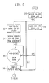
- a far-end signal x[n] is received by the near-end device 200, converted to an analog signal (not shown) and played to the recipient through speaker 250.
- a portion of the far-end signal x[n] is acoustically coupled into the near-end microphone 260.
- the acoustically coupled echo signal d[n] is fed back into the echo canceller 240.
- the far-end signal x[n] is also fed into an adaptive filter 244 which generates a filtered signal y[n].
- Any form of adaptive digital filter could be used here, for the purpose of illustration and discussion, a multi-block frequency-domain (MDF) least-mean square approach is selected to meet the complexity of the present gain control method for acoustic echo cancellation and suppression.
- MDF multi-block frequency-domain
- the MDF adaptive filter is most suitable for real time applications implemented in digital signal processing hardware.
- the MDF adaptive filter introduces smaller block delay, is faster and therefore suitable for telecommunications.
- Improved performance using the MDF adaptive filter is accomplished by using smaller block size, updating the weight factor more often, and reducing the total execution time of the adaptive process. See Soo et al., "Multidelay Block Frequency Domain Adaptive Filter," IEEE Transactions on Acoustics, Speech and Signal Processing, pp. 373-376, Feb. 1990.
- the analog echo signal received at the microphone is digitized and sampled (not shown) at the same rate of samples per second as the received digital far-end signal.
- the filtered signal y[n] from adaptive filter 244 is subtracted from echo signal d[n] to produce an error signal e[n].
- Subtracting the filtered signal y[n] from the echo signal d[n] in the echo cancellation stage 240 provides a first level of attenuation, producing error signal e[n].
- the error signal e[n] is further attenuated in the echo suppression stage 220 before transmit signal t[n] is transmitted to the far-end device.
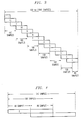
- the filter update control 242 within echo canceller 240 uses error signal e[n] to update the weights of adaptive filter 244. This uses twelve blocks wherein each successive block overlaps the previous block by fifty-percent as illustrated in figure 3. For example, referring to figure 4, the first 160 samples are in block 1. The last 80 samples in block 1 are also used for the first 80 samples of block 2 so that the combined blocks 1 and 2 comprise a total of 240 samples, of which 80 samples are duplicated. Referring back to figure 3, this provides a tail length, from the first sample in block 1 to the last sample in block 12, of 1040-16bit samples, which translates to a 130 milliseconds tail length.
- tail length is discussed and illustrated for 1040, 16 bit samples other tail lengths can be substituted.
- a tail length of 130 milliseconds was selected because a tail length greater than or equal to 120 milliseconds was found to remove the bulk amount of acoustic echo received in a typical office environment. Changing the environment in which a voice terminal incorporating the present gain control method for acoustic echo cancellation and suppression is operated, may require the tail length to be adjusted accordingly.
- the echo suppression stage of the present gain control method for acoustic echo cancellation and suppression is necessary to further reduce the echo signal to a level that is not objectionable.
- the echo suppressor adds additional attenuation because the echo cancellation stage does not sufficiently attenuate the echo signal.
- the amount of attenuation added by the echo suppression stage is dependent of the echo cancellation stage since the echo cancellation variables x[n], y[n], and e[n] are all used to calculate the attenuation factor k used to attenuate error signal e[n] to produce transmit signal t[n].
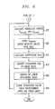
- far-end signal x[n] is received in block 510 and is filtered by adaptive filter 244 in block 570 to produce filtered signal y[n].
- far-end signal x[n] is played from speaker 250 in block 520.
- Echo signal d[n] is received at microphone 260 in block 540 and digitized as previously discussed.
- Filtered signal y[n] is subtracted from the echo signal d[n] in block 550 to produce error signal e[n].
- the power of the signals are calculated every 80 samples in block 560.
- the power calculations are used to control the adaptation speed of adaptive filter 244 and for calculating an attenuation factor for echo suppression stage 220. In this example, every 10 milliseconds the signal power is recalculated using a new string of 80 samples.
- P x , P y , and P e are used to calculate a normalized far-end and near-end power, P near-end and P far-end respectively in block 620.
- the far-end silence power is selected as 40 dB for calculating P far-end although other positive values greater than 0 dB and less than 60 dB can be substituted.
- a suppression value, A is calculated in block 650 by summing the product of the normalized far-end power multiplied by a first weighted factor, W 1 , plus the product of the normalized near-end power multiplied by a second weighted factor, W 2 to produce a suppression value in decibels.
- the weighted values, W 1 and W 2 are used to compute a weighted difference between the normalized far-end power and the normalized near-end power to compute a suppression value, A, in block 650.
- the present gain control method for acoustic echo cancellation and suppression uses normalized power difference instead of actual power differences.
- Use of actual powers in calculating attenuation gives rise to unreliability in noisy environments.
- Using normalized, or relative, powers such as the difference used to calculate the far-end and the near-end power values improves robustness to noise.
- the linear value is smoothed using a predetermined smoothing factor.
- the attenuation factor k is calculated to be a value between 0 and 1.
- Infinite attenuation is analogous to a half-duplex connection.
- the present gain control method for acoustic echo cancellation and suppression does not use explicit voice-activity detection of either the far-end or the near-end. Neither is double-talk detection used. Thus, the chance of clipping due to misclassification of the voice-activity or double talk detection is minimized.
- calculations in blocks 620, 630, 650, 670, 680 and 690 are computed to produce an attenuation factor k that is multiplied by error signal e[n] to produce a transmit signal t[n] that is sent to the far-end voice terminal.
- P x is greater than P y , P d and P e . Therefore, the normalized P far-end is large. Unlike prior art echo suppressors, this ensures attenuation even though the adaptive filter may not have reached convergence.
- Prior art echo suppressors typically operate as a half duplex connection until the adaptive filter reaches convergence.
- the values used to calculate the attention factor A in the present gain control method for acoustic echo cancellation and suppression description may be adjusted for operation in different environments. While the present gain control method for acoustic echo cancellation and suppression has been illustrated and described utilizing a particular adaptive filter, it is for illustration purpose only. Other forms of adaptive filtering, such as time-domain Normalized Least Mean Square (NLMS) or recursive Least Squares (RLS), could be used.
- NLMS time-domain Normalized Least Mean Square
- RLS recursive Least Squares
Landscapes
- Engineering & Computer Science (AREA)
- Signal Processing (AREA)
- Cable Transmission Systems, Equalization Of Radio And Reduction Of Echo (AREA)
- Telephone Function (AREA)
- Telephonic Communication Services (AREA)
- Circuit For Audible Band Transducer (AREA)
Abstract
Description

| Pnear end < C1 | W1 = 1.00 | W1 = 0.50 |
| C1 ≤Pnear end < C2 | W1 = 0.50 | W1 = 0.25 |
| Pnear end ≥C2 | W1 = 0.00 | W1 = 0.50 |
The weighted values, W1 and W2 , are used to compute a weighted difference between the normalized far-end power and the normalized near-end power to compute a suppression value, A, in
Claims (9)
- A gain control method for acoustic echo cancellation and suppression for use with a full duplex voice terminal receiving a far-end signal from a far-end voice terminal and sending a transmit signal to the far-end voice terminal, the full duplex voice terminal having an adaptive filter, a speaker and a microphone, the method comprising:playing the far-end signal at the speaker;receiving an echo signal that is acoustically coupled from the speaker to the microphone, wherein the echo signal is a portion of the far-end signal played at the speaker;filtering the far-end signal by the adaptive filter to generate a filtered signal;calculating an error signal, wherein the error signal is the difference between the echo signal minus the filtered signal;calculating an attenuation factor from the far-end signal, the filtered signal, the and the error signal, wherein the attenuation factor is between a predetermined upper limit and a predetermined lower limit; andcalculating the transmit signal, wherein the transmit signal is the product of the attenuation factor times the error signal.
- The gain control method of claim 1 wherein receiving an echo signal comprises:receiving an analog echo signal from the microphone; anddigitizing the analog echo signal at a predetermined rate of samples per second, wherein the rate of samples for second is the same rate of samples per second as the received far-end signal.
- The gain control method of claim 1, wherein calculating an attenuation factor further comprises:calculating a suppression value from the far-end signal, the filtered signal, the error signal and a predetermined silence value;smoothing the suppression value to produce a smoothed suppression value; andderiving the attenuation factor from the smoothed suppression value, wherein the attenuation factor is between the predetermined upper limit and the predetermined lower limit.
- The method of claim 3 wherein calculating an attenuation factor further comprises:converting the suppression value to a linear value;applying a predetermined smoothing factor to the linear value to produce a smoothed linear value; anddetermining the attenuation factor between the predetermined upper limit and the predetermined lower limit, wherein when the smoothed linear value is less than the predetermined lower limit the attenuation factor is equal to the predetermined lower limit and when the smoothed linear value is greater than the predetermined upper limit the attenuation factor is equal to the predetermined upper limit and when the smoothed linear value is between the predetermined upper limit and the predetermined lower limit, the attenuation factor is equal to the smoothed linear value.
- The gain control method of claim 3, wherein calculating a suppression value further comprises:calculating a far-end power from the far-end signal;calculating a normalized far-end power as the difference between the predetermined silence power minus the far-end power;calculating an error power from the error signal;calculating a filtered power from the filtered signal;calculating a normalized near-end power as the difference between the error power minus the filtered power;locating a first weighted value and a second weighted value from a table of two or more predetermined first weighted values and two or more predetermined second weighted values, wherein the normalized near-end power points to the corresponding first weighted value and the corresponding second weighted; andcalculating the suppression value as the sum of the product of the first weighted value times the normalized far-end power plus the product of the second weighted value times the normalized near-end power.
- A method of calculating an attenuation factor for use with a full duplex voice terminal comprising an echo canceller having an adaptive filter to filter a far-end signal and produce a filtered signal, and an echo suppressor comprising a processor, a speaker and a microphone that receives an acoustically coupled echo signal, the method comprising:subtracting the filtered signal from the acoustically coupled echo signal to produce an error signal;processing the far-end signal, the filtered signal, and the error signal to compute a far-end power, a filtered power, and an error power respectively;calculating a suppression value as the sum of a weighted difference between a predetermined silence power minus the far-end power plus a weighted difference between the error power minus the filtered power;converting the suppression value to a linear value; anddetermining the attenuation factor between an upper limit and a lower limit, wherein the attenuation factor is the upper limit when the linear value is greater than the upper limit, is the lower limit when the linear value is less than the lower limit and is the linear value when the linear value is between the upper limit and the lower limit.
- The method of claim 6 further comprising:applying a predetermined smoothing factor to the linear value to produce a smoothed linear value, wherein the smoothed linear value is used to determine the attenuation factor.
- The method of claim 6 wherein calculating a suppression value further comprises:calculating a normalized near-end power as the error power minus the filtered power;calculating a normalized far-end power as the predetermined silence power minus the far-end power;using the normalized near-end power to locate a first weighted value from two or more first weighted values and a second weighted value from two or more second weighted values; andcalculating the suppression value as the sum of the product of the first weighted value times the normalized far-end power plus the product of the second weighted value times the normalized near-end power.
- A gain control method for acoustic echo cancellation and suppression for use with a full duplex voice terminal having a speaker and a microphone, wherein the full duplex voice terminal receives a far-end signal x[n] from a far-end voice terminal and sends a transmit signal t[n] to the far-end voice terminal, the method comprising:filtering the far-end signal x[n] to produce a filtered signal y[n];receiving an analog echo signal from the microphone;digitizing the analog echo signal at a predetermined rate of samples per second to produce an echo signal d[n];calculating an error signal e[n] according to e[n] = d[n] - y[n];processing the far-end signal x[n], the filtered signal y[n], the echo signal d[n] and the error signal e[n] to calculate respective far-end power Px, filtered power Py, echo power Pd, and error power Pe;calculating a normalized far-end power Pfar-end according to Pfar-end = Ps - Px where Ps is a predetermined silence power;calculating a normalized near-end power Pnear-end according to Pnear-end = Pe - Py;locating a first weight W1 and a second weight W2 from a table having two or more first weights W1 and two or more corresponding second weights W2, wherein the one of the two or more first weights W1 and the one of the two or more second weights W2 is pointed to by Pnear-end;calculating a suppression value A according to A = W1Pfar-end + W2Pnear-end;converting the suppression value A to a linear suppression value kinst;applying a predetermined smoothing factor to the linear suppression value kinst to produce a smoothed linear suppression value ksmootn;determining an attenuation factor k between an upper limit and a lower limit; wherein when the smoothed linear suppression value is less than the lower limit the attenuation factor is equal to the lower limit and when the smoothed linear suppression value is greater than the upper limit the attenuation factor is equal to the upper limit and when the smoothed linear suppression value is between the upper limit and the lower limit the attenuation factor is equal to the smoothed linear suppression value; andcalculating the transmit signal t[n] according to t[n] = e[n]k.
Applications Claiming Priority (2)
| Application Number | Priority Date | Filing Date | Title |
|---|---|---|---|
| US35617 | 1993-03-23 | ||
| US10/035,617 US6961422B2 (en) | 2001-12-28 | 2001-12-28 | Gain control method for acoustic echo cancellation and suppression |
Publications (3)
| Publication Number | Publication Date |
|---|---|
| EP1324583A2 true EP1324583A2 (en) | 2003-07-02 |
| EP1324583A3 EP1324583A3 (en) | 2004-09-22 |
| EP1324583B1 EP1324583B1 (en) | 2008-08-06 |
Family
ID=21883779
Family Applications (1)
| Application Number | Title | Priority Date | Filing Date |
|---|---|---|---|
| EP02258940A Expired - Lifetime EP1324583B1 (en) | 2001-12-28 | 2002-12-24 | Gain control method for acoustic echo cancellation |
Country Status (5)
| Country | Link |
|---|---|
| US (1) | US6961422B2 (en) |
| EP (1) | EP1324583B1 (en) |
| JP (2) | JP4257113B2 (en) |
| CA (1) | CA2414972C (en) |
| DE (1) | DE60228043D1 (en) |
Cited By (1)
| Publication number | Priority date | Publication date | Assignee | Title |
|---|---|---|---|---|
| WO2004064365A1 (en) * | 2003-01-08 | 2004-07-29 | Philips Intellectual Property & Standards Gmbh | Device and method for suppressing echo, in particular in telephones |
Families Citing this family (43)
| Publication number | Priority date | Publication date | Assignee | Title |
|---|---|---|---|---|
| JP3682032B2 (en) * | 2002-05-13 | 2005-08-10 | 株式会社ダイマジック | Audio device and program for reproducing the same |
| JP3864914B2 (en) * | 2003-01-20 | 2007-01-10 | ソニー株式会社 | Echo suppression device |
| FR2856183A1 (en) * | 2003-06-13 | 2004-12-17 | France Telecom | Echo control device for e.g. general packet radio service network, has unit modifying signal captured from communication device based on information representing diffused signal and coupling separating speaker from microphone |
| US7599432B2 (en) * | 2003-12-08 | 2009-10-06 | Freescale Semiconductor, Inc. | Method and apparatus for dynamically inserting gain in an adaptive filter system |
| US20070165871A1 (en) * | 2004-01-07 | 2007-07-19 | Koninklijke Philips Electronic, N.V. | Audio system having reverberation reducing filter |
| EP1619793B1 (en) * | 2004-07-20 | 2015-06-17 | Harman Becker Automotive Systems GmbH | Audio enhancement system and method |
| DE602005020662D1 (en) * | 2004-10-13 | 2010-05-27 | Koninkl Philips Electronics Nv | ECHO CANCELLATION |
| US8457614B2 (en) | 2005-04-07 | 2013-06-04 | Clearone Communications, Inc. | Wireless multi-unit conference phone |
| US7724693B2 (en) * | 2005-07-28 | 2010-05-25 | Qnx Software Systems (Wavemakers), Inc. | Network dependent signal processing |
| US8326614B2 (en) | 2005-09-02 | 2012-12-04 | Qnx Software Systems Limited | Speech enhancement system |
| JP4814329B2 (en) * | 2005-10-21 | 2011-11-16 | コーニンクレッカ フィリップス エレクトロニクス エヌ ヴィ | Acoustic echo canceller |
| US8275120B2 (en) * | 2006-05-30 | 2012-09-25 | Microsoft Corp. | Adaptive acoustic echo cancellation |
| US8077641B2 (en) * | 2006-06-10 | 2011-12-13 | Microsoft Corporation | Echo cancellation for channels with unknown time-varying gain |
| JP4569618B2 (en) * | 2006-11-10 | 2010-10-27 | ソニー株式会社 | Echo canceller and speech processing apparatus |
| JP4705554B2 (en) * | 2006-11-14 | 2011-06-22 | 日本電信電話株式会社 | Echo canceling apparatus, method thereof, program thereof, and recording medium thereof |
| EP1950739B1 (en) * | 2007-01-23 | 2011-09-14 | Siemens Aktiengesellschaft Österreich | Method for identifying signals from the same source |
| US8155304B2 (en) * | 2007-04-10 | 2012-04-10 | Microsoft Corporation | Filter bank optimization for acoustic echo cancellation |
| WO2008134642A1 (en) | 2007-04-27 | 2008-11-06 | Personics Holdings Inc. | Method and device for personalized voice operated control |
| JP5071480B2 (en) * | 2007-08-24 | 2012-11-14 | 富士通株式会社 | Echo suppression device, echo suppression system, echo suppression method, and computer program |
| US8050398B1 (en) | 2007-10-31 | 2011-11-01 | Clearone Communications, Inc. | Adaptive conferencing pod sidetone compensator connecting to a telephonic device having intermittent sidetone |
| US8199927B1 (en) | 2007-10-31 | 2012-06-12 | ClearOnce Communications, Inc. | Conferencing system implementing echo cancellation and push-to-talk microphone detection using two-stage frequency filter |
| TWI478489B (en) * | 2007-12-19 | 2015-03-21 | Realtek Semiconductor Corp | Receive device and its auto gain control method |
| DE102008039329A1 (en) * | 2008-01-25 | 2009-07-30 | Fraunhofer-Gesellschaft zur Förderung der angewandten Forschung e.V. | An apparatus and method for calculating control information for an echo suppression filter and apparatus and method for calculating a delay value |
| JP4567804B1 (en) * | 2009-11-30 | 2010-10-20 | パナソニック株式会社 | Howling suppression device, microphone device, amplifier device, loudspeaker system, and howling suppression method |
| EP2444967A1 (en) * | 2010-10-25 | 2012-04-25 | Fraunhofer-Gesellschaft zur Förderung der Angewandten Forschung e.V. | Echo suppression comprising modeling of late reverberation components |
| WO2012094733A1 (en) * | 2011-01-10 | 2012-07-19 | 2156389 Ontario Inc. | Impact attenuating bladder with fluid release control valve for a helmet liner |
| RU2011103938A (en) * | 2011-02-03 | 2012-08-10 | ЭлЭсАй Корпорейшн (US) | CONTROL OF ACOUSTIC ECHO SIGNALS BASED ON THE TIME AREA |
| WO2014015914A1 (en) * | 2012-07-27 | 2014-01-30 | Fraunhofer-Gesellschaft zur Förderung der angewandten Forschung e.V. | Apparatus and method for providing a loudspeaker-enclosure-microphone system description |
| GB201309777D0 (en) | 2013-05-31 | 2013-07-17 | Microsoft Corp | Echo suppression |
| GB201309781D0 (en) | 2013-05-31 | 2013-07-17 | Microsoft Corp | Echo cancellation |
| GB201309771D0 (en) | 2013-05-31 | 2013-07-17 | Microsoft Corp | Echo removal |
| GB201309773D0 (en) | 2013-05-31 | 2013-07-17 | Microsoft Corp | Echo removal |
| GB201309779D0 (en) | 2013-05-31 | 2013-07-17 | Microsoft Corp | Echo removal |
| US9288572B2 (en) | 2014-01-09 | 2016-03-15 | International Business Machines Corporation | Haptic microphone |
| GB2519392B (en) * | 2014-04-02 | 2016-02-24 | Imagination Tech Ltd | Auto-tuning of an acoustic echo canceller |
| US9589556B2 (en) * | 2014-06-19 | 2017-03-07 | Yang Gao | Energy adjustment of acoustic echo replica signal for speech enhancement |
| GB201414352D0 (en) | 2014-08-13 | 2014-09-24 | Microsoft Corp | Reversed echo canceller |
| US9712866B2 (en) | 2015-04-16 | 2017-07-18 | Comigo Ltd. | Cancelling TV audio disturbance by set-top boxes in conferences |
| US9749746B2 (en) * | 2015-04-29 | 2017-08-29 | Fortemedia, Inc. | Devices and methods for reducing the processing time of the convergence of a spatial filter |
| US10122863B2 (en) * | 2016-09-13 | 2018-11-06 | Microsemi Semiconductor (U.S.) Inc. | Full duplex voice communication system and method |
| US10559317B2 (en) * | 2018-06-29 | 2020-02-11 | Cirrus Logic International Semiconductor Ltd. | Microphone array processing for adaptive echo control |
| EP4202922A1 (en) * | 2021-12-23 | 2023-06-28 | GN Audio A/S | Audio device and method for speaker extraction |
| US11902757B2 (en) * | 2022-06-14 | 2024-02-13 | Tencent America LLC | Techniques for unified acoustic echo suppression using a recurrent neural network |
Family Cites Families (11)
| Publication number | Priority date | Publication date | Assignee | Title |
|---|---|---|---|---|
| US4600815A (en) * | 1982-07-30 | 1986-07-15 | Communications Satellite Corporation | Automatic gain control for echo cancellers and similar adaptive systems |
| US5016271A (en) * | 1989-05-30 | 1991-05-14 | At&T Bell Laboratories | Echo canceler-suppressor speakerphone |
| US5274705A (en) * | 1991-09-24 | 1993-12-28 | Tellabs Inc. | Nonlinear processor for an echo canceller and method |
| JPH08204619A (en) * | 1995-01-26 | 1996-08-09 | Nec Corp | Echo suppressor |
| US5657384A (en) * | 1995-03-10 | 1997-08-12 | Tandy Corporation | Full duplex speakerphone |
| US5668794A (en) * | 1995-09-29 | 1997-09-16 | Crystal Semiconductor | Variable gain echo suppressor |
| SE505692C2 (en) * | 1995-12-18 | 1997-09-29 | Ericsson Telefon Ab L M | Method and apparatus for echo extinguishing by estimating residual signal power |
| US6185300B1 (en) * | 1996-12-31 | 2001-02-06 | Ericsson Inc. | Echo canceler for use in communications system |
| US6148078A (en) * | 1998-01-09 | 2000-11-14 | Ericsson Inc. | Methods and apparatus for controlling echo suppression in communications systems |
| US6282176B1 (en) * | 1998-03-20 | 2001-08-28 | Cirrus Logic, Inc. | Full-duplex speakerphone circuit including a supplementary echo suppressor |
| US6507653B1 (en) * | 2000-04-14 | 2003-01-14 | Ericsson Inc. | Desired voice detection in echo suppression |
-
2001
- 2001-12-28 US US10/035,617 patent/US6961422B2/en not_active Expired - Lifetime
-
2002
- 2002-12-23 CA CA002414972A patent/CA2414972C/en not_active Expired - Fee Related
- 2002-12-24 DE DE60228043T patent/DE60228043D1/en not_active Expired - Fee Related
- 2002-12-24 EP EP02258940A patent/EP1324583B1/en not_active Expired - Lifetime
- 2002-12-27 JP JP2002382276A patent/JP4257113B2/en not_active Expired - Fee Related
-
2008
- 2008-10-29 JP JP2008278341A patent/JP2009065699A/en active Pending
Cited By (1)
| Publication number | Priority date | Publication date | Assignee | Title |
|---|---|---|---|---|
| WO2004064365A1 (en) * | 2003-01-08 | 2004-07-29 | Philips Intellectual Property & Standards Gmbh | Device and method for suppressing echo, in particular in telephones |
Also Published As
| Publication number | Publication date |
|---|---|
| CA2414972C (en) | 2008-08-26 |
| EP1324583B1 (en) | 2008-08-06 |
| DE60228043D1 (en) | 2008-09-18 |
| JP2009065699A (en) | 2009-03-26 |
| EP1324583A3 (en) | 2004-09-22 |
| CA2414972A1 (en) | 2003-06-28 |
| JP2003234679A (en) | 2003-08-22 |
| JP4257113B2 (en) | 2009-04-22 |
| US20030123674A1 (en) | 2003-07-03 |
| US6961422B2 (en) | 2005-11-01 |
Similar Documents
| Publication | Publication Date | Title |
|---|---|---|
| US6961422B2 (en) | Gain control method for acoustic echo cancellation and suppression | |
| US6442272B1 (en) | Voice conferencing system having local sound amplification | |
| US5386465A (en) | Audio processing system for teleconferencing with high and low transmission delays | |
| CN101262530B (en) | A device for eliminating echo of mobile terminal | |
| US5612996A (en) | Loop gain processing system for speakerphone applications | |
| US5764753A (en) | Half-duplex controller | |
| US5390244A (en) | Method and apparatus for periodic signal detection | |
| JPH07508866A (en) | Methods of fail-safe operation in speakerphone systems | |
| JPH09172396A (en) | System and method for removing influence of acoustic coupling | |
| CN1003555B (en) | Full-duplex handset for wireless and wireline telephones | |
| EP1446894A1 (en) | Echo canceller ensuring further reduction in residual echo | |
| US6381224B1 (en) | Method and apparatus for controlling a full-duplex communication system | |
| JP2002501336A (en) | Echo suppression control method and apparatus in communication system | |
| EP1264418B1 (en) | A method and system for stereo echo cancellation for voip communication systems | |
| US6108412A (en) | Adaptive echo cancelling system for telephony applications | |
| US6560332B1 (en) | Methods and apparatus for improving echo suppression in bi-directional communications systems | |
| EP1786191B1 (en) | Acoustic echo canceller | |
| US6178162B1 (en) | Method and apparatus for inhibiting echo in a channel of a communication system | |
| CN113921029A (en) | Double-end sounding detection method applied to echo cancellation | |
| JP3220979B2 (en) | Voice switch | |
| JPH09116469A (en) | Echo noise cancellor and echo noise canceling method | |
| JP3941581B2 (en) | Loudspeaker | |
| JP4900185B2 (en) | Loudspeaker | |
| CN1663230A (en) | unstable echo canceller | |
| JPH0465923A (en) | Sound signal processor and method thereof |
Legal Events
| Date | Code | Title | Description |
|---|---|---|---|
| PUAI | Public reference made under article 153(3) epc to a published international application that has entered the european phase |
Free format text: ORIGINAL CODE: 0009012 |
|
| AK | Designated contracting states |
Designated state(s): AT BE BG CH CY CZ DE DK EE ES FI FR GB GR IE IT LI LU MC NL PT SE SI SK TR |
|
| AX | Request for extension of the european patent |
Extension state: AL LT LV MK RO |
|
| PUAL | Search report despatched |
Free format text: ORIGINAL CODE: 0009013 |
|
| AK | Designated contracting states |
Kind code of ref document: A3 Designated state(s): AT BE BG CH CY CZ DE DK EE ES FI FR GB GR IE IT LI LU MC NL PT SE SI SK TR |
|
| AX | Request for extension of the european patent |
Extension state: AL LT LV MK RO |
|
| 17P | Request for examination filed |
Effective date: 20050314 |
|
| AKX | Designation fees paid |
Designated state(s): DE FR GB IT |
|
| 17Q | First examination report despatched |
Effective date: 20061108 |
|
| GRAP | Despatch of communication of intention to grant a patent |
Free format text: ORIGINAL CODE: EPIDOSNIGR1 |
|
| GRAS | Grant fee paid |
Free format text: ORIGINAL CODE: EPIDOSNIGR3 |
|
| GRAA | (expected) grant |
Free format text: ORIGINAL CODE: 0009210 |
|
| AK | Designated contracting states |
Kind code of ref document: B1 Designated state(s): DE FR GB IT |
|
| REG | Reference to a national code |
Ref country code: GB Ref legal event code: FG4D |
|
| REF | Corresponds to: |
Ref document number: 60228043 Country of ref document: DE Date of ref document: 20080918 Kind code of ref document: P |
|
| PGFP | Annual fee paid to national office [announced via postgrant information from national office to epo] |
Ref country code: FR Payment date: 20081212 Year of fee payment: 7 |
|
| REG | Reference to a national code |
Ref country code: GB Ref legal event code: 732E Free format text: REGISTERED BETWEEN 20090430 AND 20090506 |
|
| PGFP | Annual fee paid to national office [announced via postgrant information from national office to epo] |
Ref country code: DE Payment date: 20081219 Year of fee payment: 7 |
|
| PLBE | No opposition filed within time limit |
Free format text: ORIGINAL CODE: 0009261 |
|
| STAA | Information on the status of an ep patent application or granted ep patent |
Free format text: STATUS: NO OPPOSITION FILED WITHIN TIME LIMIT |
|
| PGFP | Annual fee paid to national office [announced via postgrant information from national office to epo] |
Ref country code: GB Payment date: 20081224 Year of fee payment: 7 |
|
| 26N | No opposition filed |
Effective date: 20090507 |
|
| PG25 | Lapsed in a contracting state [announced via postgrant information from national office to epo] |
Ref country code: IT Free format text: LAPSE BECAUSE OF FAILURE TO SUBMIT A TRANSLATION OF THE DESCRIPTION OR TO PAY THE FEE WITHIN THE PRESCRIBED TIME-LIMIT Effective date: 20080806 |
|
| GBPC | Gb: european patent ceased through non-payment of renewal fee |
Effective date: 20091224 |
|
| REG | Reference to a national code |
Ref country code: FR Ref legal event code: ST Effective date: 20100831 |
|
| PG25 | Lapsed in a contracting state [announced via postgrant information from national office to epo] |
Ref country code: FR Free format text: LAPSE BECAUSE OF NON-PAYMENT OF DUE FEES Effective date: 20091231 |
|
| PG25 | Lapsed in a contracting state [announced via postgrant information from national office to epo] |
Ref country code: DE Free format text: LAPSE BECAUSE OF NON-PAYMENT OF DUE FEES Effective date: 20100701 |
|
| PG25 | Lapsed in a contracting state [announced via postgrant information from national office to epo] |
Ref country code: GB Free format text: LAPSE BECAUSE OF NON-PAYMENT OF DUE FEES Effective date: 20091224 |