EP1324463A2 - Rotary electric machine having conductors inserted into core slot with slot insulation sleeve - Google Patents
Rotary electric machine having conductors inserted into core slot with slot insulation sleeve Download PDFInfo
- Publication number
- EP1324463A2 EP1324463A2 EP02028262A EP02028262A EP1324463A2 EP 1324463 A2 EP1324463 A2 EP 1324463A2 EP 02028262 A EP02028262 A EP 02028262A EP 02028262 A EP02028262 A EP 02028262A EP 1324463 A2 EP1324463 A2 EP 1324463A2
- Authority
- EP
- European Patent Office
- Prior art keywords
- insulation sleeve
- slot
- conductors
- rotary electric
- electric machine
- Prior art date
- Legal status (The legal status is an assumption and is not a legal conclusion. Google has not performed a legal analysis and makes no representation as to the accuracy of the status listed.)
- Granted
Links
Images


Classifications
-
- H—ELECTRICITY
- H02—GENERATION; CONVERSION OR DISTRIBUTION OF ELECTRIC POWER
- H02K—DYNAMO-ELECTRIC MACHINES
- H02K3/00—Details of windings
- H02K3/32—Windings characterised by the shape, form or construction of the insulation
- H02K3/34—Windings characterised by the shape, form or construction of the insulation between conductors or between conductor and core, e.g. slot insulation
-
- H—ELECTRICITY
- H02—GENERATION; CONVERSION OR DISTRIBUTION OF ELECTRIC POWER
- H02K—DYNAMO-ELECTRIC MACHINES
- H02K15/00—Processes or apparatus specially adapted for manufacturing, assembling, maintaining or repairing of dynamo-electric machines
- H02K15/10—Applying solid insulation to windings, stators or rotors, e.g. applying insulating tapes
-
- H—ELECTRICITY
- H02—GENERATION; CONVERSION OR DISTRIBUTION OF ELECTRIC POWER
- H02K—DYNAMO-ELECTRIC MACHINES
- H02K3/00—Details of windings
- H02K3/32—Windings characterised by the shape, form or construction of the insulation
- H02K3/34—Windings characterised by the shape, form or construction of the insulation between conductors or between conductor and core, e.g. slot insulation
- H02K3/345—Windings characterised by the shape, form or construction of the insulation between conductors or between conductor and core, e.g. slot insulation between conductor and core, e.g. slot insulation
-
- Y—GENERAL TAGGING OF NEW TECHNOLOGICAL DEVELOPMENTS; GENERAL TAGGING OF CROSS-SECTIONAL TECHNOLOGIES SPANNING OVER SEVERAL SECTIONS OF THE IPC; TECHNICAL SUBJECTS COVERED BY FORMER USPC CROSS-REFERENCE ART COLLECTIONS [XRACs] AND DIGESTS
- Y10—TECHNICAL SUBJECTS COVERED BY FORMER USPC
- Y10T—TECHNICAL SUBJECTS COVERED BY FORMER US CLASSIFICATION
- Y10T29/00—Metal working
- Y10T29/49—Method of mechanical manufacture
- Y10T29/49002—Electrical device making
- Y10T29/49009—Dynamoelectric machine
-
- Y—GENERAL TAGGING OF NEW TECHNOLOGICAL DEVELOPMENTS; GENERAL TAGGING OF CROSS-SECTIONAL TECHNOLOGIES SPANNING OVER SEVERAL SECTIONS OF THE IPC; TECHNICAL SUBJECTS COVERED BY FORMER USPC CROSS-REFERENCE ART COLLECTIONS [XRACs] AND DIGESTS
- Y10—TECHNICAL SUBJECTS COVERED BY FORMER USPC
- Y10T—TECHNICAL SUBJECTS COVERED BY FORMER US CLASSIFICATION
- Y10T29/00—Metal working
- Y10T29/49—Method of mechanical manufacture
- Y10T29/49002—Electrical device making
- Y10T29/49009—Dynamoelectric machine
- Y10T29/49012—Rotor
-
- Y—GENERAL TAGGING OF NEW TECHNOLOGICAL DEVELOPMENTS; GENERAL TAGGING OF CROSS-SECTIONAL TECHNOLOGIES SPANNING OVER SEVERAL SECTIONS OF THE IPC; TECHNICAL SUBJECTS COVERED BY FORMER USPC CROSS-REFERENCE ART COLLECTIONS [XRACs] AND DIGESTS
- Y10—TECHNICAL SUBJECTS COVERED BY FORMER USPC
- Y10T—TECHNICAL SUBJECTS COVERED BY FORMER US CLASSIFICATION
- Y10T29/00—Metal working
- Y10T29/53—Means to assemble or disassemble
- Y10T29/5313—Means to assemble electrical device
- Y10T29/53143—Motor or generator
- Y10T29/53152—Means to position insulation
Definitions
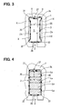
- the insulation sleeve 3 in its cross-section, includes four corner portions 31, 32, 33, 34 and four flat portions 35, 36, 37, 38.
- the corner portions 31-34 contact respective corners of the slot 2, and the flat portions 35, 36 are positioned in parallel to sidewalls 2a of the slot 2 forming certain spaces therebetween.
- the flat portion 37 including an overlapped portion is positioned in parallel to upper wall of the slot 2 forming a certain space therebetween.
- the flat portion 38 is positioned in contact with a lower wall of the slot 2.
- the present invention is not limited to the embodiment described above, but it may be variously modified.
- the cross-section of the insulation sleeve 3 is formed in a substantially rectangular shape in the foregoing embodiment, the cross-section may be formed in other shapes as long as the inner space is widened by inserting the conductors 4a and the corner portions 31-34 are pushed against the corners of the slot 2.
- the bending lines X may not be made as continuous lines, but they may be made intermittently. It is preferable to thermally connect the overlapping portion on the flat portion 37, but it may be simply overlapped without being connected. The overlapping portion on the flat portion 37 may be eliminated, and both ends of the resin tape may be abutted and connected to each other.
Landscapes
- Engineering & Computer Science (AREA)
- Power Engineering (AREA)
- Manufacturing & Machinery (AREA)
- Insulation, Fastening Of Motor, Generator Windings (AREA)
- Manufacture Of Motors, Generators (AREA)
- Windings For Motors And Generators (AREA)
Abstract
Description
Claims (4)
- A rotary electric machine comprising:a core (1) forming a stator or a rotor of the rotary electric machine, a plurality of slots (2) each having a substantially rectangular cross-section being formed in the core;an insulation sleeve (3) having a substantially rectangular cross-section inserted into each slot; andconductors (4a) inserted into the insulation sleeve, wherein:the insulation sleeve (3) includes corner portions (31-34) contacting respective corners of the slot and flat portions (35-38) positioned in parallel to sidewalls (2a) of the slot;the flat portions of the insulation sleeve are positioned apart from the sidewalls of the slot, forming certain spaces therebetween when the conductors are not inserted into the insulation sleeve; anda cross-sectional size of the conductors (4a) is so made that the flat portions of the insulation sleeve are pushed against the sidewalls of the slot when the conductors are inserted into the insulation sleeve.
- The rotary electric machine as in claim 1, wherein:the insulation sleeve (3) has bending lines (X) each extending along a boundary between the corner portion and the flat portion.
- The rotary electric machine as in claim 1, wherein:one of the longitudinal ends of the insulation sleeve from which the conductors are inserted is widened in a trumpet shape (5).
- A method of manufacturing the rotary electric machine defined in claim 1, the method comprising:forming the bending lines (X) by plastically deforming a resin tape from which the insulation sleeve (3) is made, the bending lines extending in a longitudinal direction of the resin tape;folding the resin tape in a shape of the insulation sleeve (3);cutting the folded resin tape into an individual insulating sleeve having a predetermined longitudinal length;inserting the insulation sleeve (3) into each slot (2); andinserting the conductors (4a) into the insulation sleeve, thereby enlarging an inner space of the insulation sleeve and pushing the corner portions (31-34) of the insulation sleeve against respective corners of the slot (2).
Applications Claiming Priority (2)
| Application Number | Priority Date | Filing Date | Title |
|---|---|---|---|
| JP2001394352 | 2001-12-26 | ||
| JP2001394352A JP3551375B2 (en) | 2001-12-26 | 2001-12-26 | Rotating electric machine and method of manufacturing the same |
Publications (3)
| Publication Number | Publication Date |
|---|---|
| EP1324463A2 true EP1324463A2 (en) | 2003-07-02 |
| EP1324463A3 EP1324463A3 (en) | 2004-05-19 |
| EP1324463B1 EP1324463B1 (en) | 2005-05-25 |
Family
ID=19188855
Family Applications (1)
| Application Number | Title | Priority Date | Filing Date |
|---|---|---|---|
| EP02028262A Expired - Lifetime EP1324463B1 (en) | 2001-12-26 | 2002-12-16 | Rotary electric machine having conductors inserted into core slot with slot insulation sleeve |
Country Status (5)
| Country | Link |
|---|---|
| US (1) | US6674211B2 (en) |
| EP (1) | EP1324463B1 (en) |
| JP (1) | JP3551375B2 (en) |
| KR (1) | KR100478694B1 (en) |
| DE (1) | DE60204275T2 (en) |
Cited By (6)
| Publication number | Priority date | Publication date | Assignee | Title |
|---|---|---|---|---|
| RU2354029C2 (en) * | 2003-07-08 | 2009-04-27 | Бейкер Хьюз Инкорпорейтед | Electric motor |
| ITPI20130092A1 (en) * | 2013-10-18 | 2015-04-19 | Atop Spa | EQUIPMENT AND METHOD TO PRODUCE COMPONENTS OF DYNAMOELECTRIC MACHINES |
| US10224789B2 (en) | 2011-03-07 | 2019-03-05 | Atop S.P.A. | Apparatus for aligning conductors of coil members in cores of electric dynamo machines |
| US10411570B2 (en) | 2011-05-16 | 2019-09-10 | Atop S.P.A. | Apparatus for manufacturing coil members for cores of dynamo electric machines by bending |
| US10749418B2 (en) | 2015-04-30 | 2020-08-18 | Atop S.P.A. | Methods for forming woven undulated coil assemblies |
| US11557946B2 (en) | 2015-07-20 | 2023-01-17 | Atop S.P.A. | Method for inserting undulated coil assemblies in slots of cores of dynamoelectric machines |
Families Citing this family (29)
| Publication number | Priority date | Publication date | Assignee | Title |
|---|---|---|---|---|
| JP4001040B2 (en) * | 2003-03-28 | 2007-10-31 | 株式会社デンソー | Rotating electric machine stator |
| JP3903964B2 (en) * | 2003-06-18 | 2007-04-11 | 株式会社デンソー | Rotating electric machine stator |
| US7472724B2 (en) | 2003-08-18 | 2009-01-06 | Electrolock, Inc. | Method and apparatus for creating, using, and dispensing tubes |
| EP1661228A4 (en) * | 2003-09-05 | 2016-11-23 | Black & Decker Inc | EXCITATION ASSEMBLIES AND PROCESS FOR PRODUCING THE SAME |
| DE10361670B4 (en) * | 2003-12-30 | 2009-08-06 | Mitsubishi Denki K.K. | Stator of a rotating electrical machine |
| US8595915B2 (en) * | 2004-01-02 | 2013-12-03 | Mitsubishi Denki Kabushiki Kaisha | Stator of electric rotating machine |
| KR100629869B1 (en) * | 2004-05-25 | 2006-09-29 | 엘지전자 주식회사 | Rotor slot structure of universal motor |
| US7081697B2 (en) * | 2004-06-16 | 2006-07-25 | Visteon Global Technologies, Inc. | Dynamoelectric machine stator core with mini caps |
| JP4640008B2 (en) * | 2005-07-15 | 2011-03-02 | 株式会社デンソー | Rotating electric machine for vehicles |
| JP4957948B2 (en) * | 2006-03-24 | 2012-06-20 | 株式会社デンソー | Insulating member and assembly method thereof |
| JP2009131019A (en) * | 2007-11-22 | 2009-06-11 | Denso Corp | Rotating machine armature |
| JP5011152B2 (en) * | 2008-02-14 | 2012-08-29 | 株式会社日立製作所 | Rotating electric machine and method of manufacturing rotating electric machine |
| US20110025160A1 (en) * | 2009-08-03 | 2011-02-03 | Gm Global Technology Operations, Inc. | Rectangular cross-section windings for electrical machine rotors |
| US8497617B2 (en) * | 2009-07-15 | 2013-07-30 | GM Global Technology Operations LLC | Stators with improved conductor assembly and method of making same |
| US8918986B2 (en) * | 2010-03-03 | 2014-12-30 | Tecnomatic S.P.A. | Method for making a high fill factor stator for an electrical machine |
| JP5546373B2 (en) * | 2010-06-30 | 2014-07-09 | 株式会社ミツバ | Rotating electric machine |
| JP2012222944A (en) * | 2011-04-07 | 2012-11-12 | Toyota Motor Corp | Stator |
| JP5839851B2 (en) * | 2011-06-23 | 2016-01-06 | 日立オートモティブシステムズ株式会社 | Rotating electric machine |
| JP5682603B2 (en) * | 2012-08-10 | 2015-03-11 | 株式会社デンソー | Rotating electrical machine stator for vehicles |
| JP5376028B1 (en) * | 2012-09-19 | 2013-12-25 | 株式会社安川電機 | Stator and rotating electric machine |
| US8907541B2 (en) * | 2012-09-25 | 2014-12-09 | Remy Technologies, L.L.C. | Slot liner for electro-dynamic machine |
| JP6156679B2 (en) * | 2013-01-25 | 2017-07-05 | 株式会社デンソー | Rotating electric machine stator |
| JP7218180B2 (en) * | 2017-01-16 | 2023-02-06 | 本田技研工業株式会社 | Insulating member, stator of rotating electric machine and rotating electric machine |
| DE102018124561A1 (en) * | 2018-10-05 | 2020-04-09 | Bayerische Motoren Werke Aktiengesellschaft | Method for manufacturing an electric motor and device |
| DE102020119303A1 (en) | 2020-07-22 | 2022-01-27 | Schaeffler Technologies AG & Co. KG | Method and device for introducing insulated winding packs into stator or rotor slots, as well as stator or rotor with insulated winding packs |
| DE102021115010B4 (en) | 2021-06-10 | 2023-02-09 | Dr. Ing. H.C. F. Porsche Aktiengesellschaft | Process for manufacturing a stator for an electrical machine |
| JP7615001B2 (en) * | 2021-10-01 | 2025-01-16 | 株式会社東芝 | Stator of rotating electrical machine |
| US12113413B2 (en) * | 2021-10-31 | 2024-10-08 | Ford Global Technologies, Llc | Electrified vehicle having electric machine stator with embedded wire support overmold |
| US20250125673A1 (en) * | 2023-10-12 | 2025-04-17 | Borgwarner Inc. | Electric Machine Stator with Sealed End Ring |
Family Cites Families (12)
| Publication number | Priority date | Publication date | Assignee | Title |
|---|---|---|---|---|
| US1661355A (en) * | 1926-03-29 | 1928-03-06 | Delcc Remy Corp | Method and machine for lining an armature core with a flexible strip |
| US3130335A (en) * | 1961-04-17 | 1964-04-21 | Epoxylite Corp | Dynamo-electric machine |
| US3515923A (en) * | 1969-04-04 | 1970-06-02 | Du Pont | Dynamoelectric machine and corrugated plastic slot liner insert therefor |
| JPS5850092B2 (en) * | 1979-11-28 | 1983-11-08 | 株式会社日立製作所 | rotor |
| JPS58157349A (en) | 1982-03-15 | 1983-09-19 | Toshiba Corp | Manufacture of insulated core for rotary electric machine |
| US4994700A (en) * | 1990-02-15 | 1991-02-19 | Sundstrand Corporation | Dynamoelectric machine oil-cooled stator winding |
| JPH08237897A (en) | 1995-02-24 | 1996-09-13 | Matsushita Seiko Co Ltd | Induction motor stator |
| JP3899685B2 (en) * | 1998-06-26 | 2007-03-28 | 株式会社デンソー | Stator for vehicle alternator and manufacturing method thereof |
| JP3196738B2 (en) | 1998-09-11 | 2001-08-06 | 株式会社デンソー | Stator manufacturing apparatus and stator manufacturing method |
| JP3843644B2 (en) | 1999-04-14 | 2006-11-08 | 株式会社デンソー | Stator for rotating electrical machine and method for manufacturing the same |
| JP2001037131A (en) | 1999-07-15 | 2001-02-09 | Mitsubishi Electric Corp | AC generator for vehicles |
| JP3621633B2 (en) * | 2000-08-02 | 2005-02-16 | 三菱電機株式会社 | Armature of rotating electric machine and manufacturing method thereof |
-
2001
- 2001-12-26 JP JP2001394352A patent/JP3551375B2/en not_active Expired - Lifetime
-
2002
- 2002-12-16 EP EP02028262A patent/EP1324463B1/en not_active Expired - Lifetime
- 2002-12-16 DE DE60204275T patent/DE60204275T2/en not_active Expired - Lifetime
- 2002-12-20 US US10/323,973 patent/US6674211B2/en not_active Expired - Lifetime
- 2002-12-24 KR KR10-2002-0083712A patent/KR100478694B1/en not_active Expired - Lifetime
Cited By (14)
| Publication number | Priority date | Publication date | Assignee | Title |
|---|---|---|---|---|
| RU2354029C2 (en) * | 2003-07-08 | 2009-04-27 | Бейкер Хьюз Инкорпорейтед | Electric motor |
| US10224789B2 (en) | 2011-03-07 | 2019-03-05 | Atop S.P.A. | Apparatus for aligning conductors of coil members in cores of electric dynamo machines |
| US10411570B2 (en) | 2011-05-16 | 2019-09-10 | Atop S.P.A. | Apparatus for manufacturing coil members for cores of dynamo electric machines by bending |
| CN105684278A (en) * | 2013-10-18 | 2016-06-15 | Atop有限公司 | Apparatus and method for manufacturing components of dynamoelectric machines |
| US9722475B2 (en) | 2013-10-18 | 2017-08-01 | Atop S.P.A | Apparatus and method for manufacturing components of dynamoelectric machines |
| CN105684278B (en) * | 2013-10-18 | 2018-08-10 | Atop有限公司 | Device and method for component manufacturing of electric machines |
| WO2015055445A3 (en) * | 2013-10-18 | 2015-06-18 | Atop S.P.A. | Apparatus and method for manufacturing components of dynamoelectric machines |
| US10305354B2 (en) | 2013-10-18 | 2019-05-28 | Atop S.P.A. | Apparatus for manufacturing components of dynamoelectric machines |
| ITPI20130092A1 (en) * | 2013-10-18 | 2015-04-19 | Atop Spa | EQUIPMENT AND METHOD TO PRODUCE COMPONENTS OF DYNAMOELECTRIC MACHINES |
| US10749418B2 (en) | 2015-04-30 | 2020-08-18 | Atop S.P.A. | Methods for forming woven undulated coil assemblies |
| US11336160B2 (en) | 2015-04-30 | 2022-05-17 | Atop S.Pa. | Methods for forming woven undulated coil assemblies |
| US11658553B2 (en) | 2015-04-30 | 2023-05-23 | Atop S.P.A. | Apparatuses for forming woven undulated coil assemblies |
| US11557946B2 (en) | 2015-07-20 | 2023-01-17 | Atop S.P.A. | Method for inserting undulated coil assemblies in slots of cores of dynamoelectric machines |
| US12470114B2 (en) | 2015-07-20 | 2025-11-11 | Atop S.P.A. | Apparatus for inserting an undulated coil assembly in slots of a core of a stator of a dynamoelectric machine |
Also Published As
| Publication number | Publication date |
|---|---|
| DE60204275T2 (en) | 2006-02-02 |
| KR20030055159A (en) | 2003-07-02 |
| US6674211B2 (en) | 2004-01-06 |
| DE60204275D1 (en) | 2005-06-30 |
| EP1324463B1 (en) | 2005-05-25 |
| JP3551375B2 (en) | 2004-08-04 |
| US20030127936A1 (en) | 2003-07-10 |
| KR100478694B1 (en) | 2005-03-28 |
| EP1324463A3 (en) | 2004-05-19 |
| JP2003199278A (en) | 2003-07-11 |
Similar Documents
| Publication | Publication Date | Title |
|---|---|---|
| EP1324463B1 (en) | Rotary electric machine having conductors inserted into core slot with slot insulation sleeve | |
| US4656380A (en) | Commutator with winding connection segments having cutting edges | |
| US6476530B1 (en) | Stator of alternator for use in automotive vehicle | |
| CN102857046B (en) | The manufacture method of stator, stator and motor | |
| CN105453388A (en) | Rotating electrical machine | |
| US3760339A (en) | Connector for plug in field | |
| US4247978A (en) | Methods of making slot liners and stator assemblies including same | |
| EP1376824A3 (en) | Stator coil made of joined conductor segments for rotary electric machinery and method for manufacturing the same | |
| US7210214B2 (en) | Method of immulating between coils of different phases of electric motor | |
| CN114977557A (en) | Stator of electric motor, and method for manufacturing stator | |
| JP2004201446A (en) | Wedge for stator core | |
| US5068563A (en) | Tab insulators for insulating armature core slots | |
| TW201818638A (en) | Permanent magnet rotary electric machine and compessor using same | |
| US7560850B2 (en) | Interphase insulating sheet and stator having the same | |
| JP2003070201A (en) | Stator for rotating electric machine and method of manufacturing the same | |
| US4151436A (en) | Electrical insulator for slotted magnetic cores | |
| JPH02142347A (en) | Armature | |
| JPH09131012A (en) | Insulator between coils of rotating electric machine stator | |
| KR102198315B1 (en) | Apparatus for cutting and chamfering insulation film | |
| JP4452984B2 (en) | Method for manufacturing stator winding of rotating electric machine | |
| JPS5959037A (en) | Interphase insulating structure for rotary electric machine | |
| JPH0555748U (en) | Interphase insulation device | |
| CN118737688A (en) | Conductor forming method | |
| WO2022050285A1 (en) | Insulator, electric motor, and applied equipment provided with electric motor | |
| JP2000041352A (en) | Induction motor |
Legal Events
| Date | Code | Title | Description |
|---|---|---|---|
| PUAI | Public reference made under article 153(3) epc to a published international application that has entered the european phase |
Free format text: ORIGINAL CODE: 0009012 |
|
| AK | Designated contracting states |
Designated state(s): AT BE BG CH CY CZ DE DK EE ES FI FR GB GR IE IT LI LU MC NL PT SE SI SK TR |
|
| AX | Request for extension of the european patent |
Extension state: AL LT LV MK RO |
|
| PUAL | Search report despatched |
Free format text: ORIGINAL CODE: 0009013 |
|
| AK | Designated contracting states |
Kind code of ref document: A3 Designated state(s): AT BE BG CH CY CZ DE DK EE ES FI FR GB GR IE IT LI LU MC NL PT SE SI SK TR |
|
| AX | Request for extension of the european patent |
Extension state: AL LT LV MK RO |
|
| 17P | Request for examination filed |
Effective date: 20040428 |
|
| GRAP | Despatch of communication of intention to grant a patent |
Free format text: ORIGINAL CODE: EPIDOSNIGR1 |
|
| AKX | Designation fees paid |
Designated state(s): DE FR GB IT |
|
| GRAS | Grant fee paid |
Free format text: ORIGINAL CODE: EPIDOSNIGR3 |
|
| GRAA | (expected) grant |
Free format text: ORIGINAL CODE: 0009210 |
|
| AK | Designated contracting states |
Kind code of ref document: B1 Designated state(s): DE FR GB IT |
|
| REG | Reference to a national code |
Ref country code: GB Ref legal event code: FG4D |
|
| REG | Reference to a national code |
Ref country code: IE Ref legal event code: FG4D |
|
| REF | Corresponds to: |
Ref document number: 60204275 Country of ref document: DE Date of ref document: 20050630 Kind code of ref document: P |
|
| ET | Fr: translation filed | ||
| PLBE | No opposition filed within time limit |
Free format text: ORIGINAL CODE: 0009261 |
|
| STAA | Information on the status of an ep patent application or granted ep patent |
Free format text: STATUS: NO OPPOSITION FILED WITHIN TIME LIMIT |
|
| 26N | No opposition filed |
Effective date: 20060228 |
|
| REG | Reference to a national code |
Ref country code: FR Ref legal event code: PLFP Year of fee payment: 14 |
|
| REG | Reference to a national code |
Ref country code: FR Ref legal event code: PLFP Year of fee payment: 15 |
|
| REG | Reference to a national code |
Ref country code: FR Ref legal event code: PLFP Year of fee payment: 16 |
|
| PGFP | Annual fee paid to national office [announced via postgrant information from national office to epo] |
Ref country code: DE Payment date: 20211210 Year of fee payment: 20 Ref country code: GB Payment date: 20211221 Year of fee payment: 20 Ref country code: FR Payment date: 20211224 Year of fee payment: 20 |
|
| PGFP | Annual fee paid to national office [announced via postgrant information from national office to epo] |
Ref country code: IT Payment date: 20211224 Year of fee payment: 20 |
|
| REG | Reference to a national code |
Ref country code: DE Ref legal event code: R071 Ref document number: 60204275 Country of ref document: DE |
|
| REG | Reference to a national code |
Ref country code: GB Ref legal event code: PE20 Expiry date: 20221215 |
|
| PG25 | Lapsed in a contracting state [announced via postgrant information from national office to epo] |
Ref country code: GB Free format text: LAPSE BECAUSE OF EXPIRATION OF PROTECTION Effective date: 20221215 |