EP1324446A2 - Spark plug and method for manufacturing the spark plug - Google Patents
Spark plug and method for manufacturing the spark plug Download PDFInfo
- Publication number
- EP1324446A2 EP1324446A2 EP02258868A EP02258868A EP1324446A2 EP 1324446 A2 EP1324446 A2 EP 1324446A2 EP 02258868 A EP02258868 A EP 02258868A EP 02258868 A EP02258868 A EP 02258868A EP 1324446 A2 EP1324446 A2 EP 1324446A2
- Authority
- EP
- European Patent Office
- Prior art keywords
- metallic shell
- insulator
- axis
- crimped
- metallic
- Prior art date
- Legal status (The legal status is an assumption and is not a legal conclusion. Google has not performed a legal analysis and makes no representation as to the accuracy of the status listed.)
- Granted
Links
Images


Classifications
-
- H—ELECTRICITY
- H01—ELECTRIC ELEMENTS
- H01T—SPARK GAPS; OVERVOLTAGE ARRESTERS USING SPARK GAPS; SPARKING PLUGS; CORONA DEVICES; GENERATING IONS TO BE INTRODUCED INTO NON-ENCLOSED GASES
- H01T21/00—Apparatus or processes specially adapted for the manufacture or maintenance of spark gaps or sparking plugs
- H01T21/02—Apparatus or processes specially adapted for the manufacture or maintenance of spark gaps or sparking plugs of sparking plugs
-
- H—ELECTRICITY
- H01—ELECTRIC ELEMENTS
- H01T—SPARK GAPS; OVERVOLTAGE ARRESTERS USING SPARK GAPS; SPARKING PLUGS; CORONA DEVICES; GENERATING IONS TO BE INTRODUCED INTO NON-ENCLOSED GASES
- H01T13/00—Sparking plugs
- H01T13/20—Sparking plugs characterised by features of the electrodes or insulation
- H01T13/36—Sparking plugs characterised by features of the electrodes or insulation characterised by the joint between insulation and body, e.g. using cement
Definitions
- the present invention relates to a spark plug used for providing ignition of an internal combustion engine.
- the metallic shell of a spark plug is fixedly attached to an insulator by means of crimping.
- the insulator is inserted into the metallic shell formed into a tubular shape, and then by use of dies a compressive load is applied to the peripheral edge of a rear end portion (a portion to be crimped) of the metallic shell.
- the portion to be crimped is curved toward a flange-like protrusion formed on the outer circumferential surface of the insulator to thereby become a crimped portion, whereby the insulator is fixed in place.
- the metallic shell is generally formed from a steel material such as carbon steel.
- a method for firmly joining the insulator 2 to the metallic shell 1 by means of the crimped portion 1d is specifically carried out in the following manner.
- Step (a) of FIG. 2 when a portion-to-be-crimped 1d' is axially compressed by means of crimping die 111, the portion-to-be-crimped 1d' is plastically deformed radially inward.
- a thread packing 61 for example, is disposed between the portion-to-be deformed 1d' and a flange-like protrusion 2e.
- a load begins to be imposed on the thread packing 61 and the flange-like protrusion 2e (hereinafter, these are generically and collectively called a "portion to be compressed"). While the portion to be compressed undergoes compressive deformation, plastic deformation of the portion-to-be-crimped 1d' proceeds further. Then, as shown in Step (b) of FIG. 2, when a final value for a compression stroke for crimping is reached, unloading is performed to thereby complete the crimping process (the portion-to-be-crimped 1d' becomes a crimped portion 1d). The unloading induces some springback of the crimped portion 1d.
- the crimped portion 1d since the crimped portion 1d is plastically deformed, the crimped portion 1d retains the compressed portion in an elastically deformed condition, thereby inducing a fastening force for firmly joining the insulator 2 to the metallic shell 1. In some cases, the thread packing 61 may not be provided.
- the above-mentioned crimping process is performed, for example, in the following manner. Crimping is performed while electricity is supplied to the metallic shell via the die to thereby heat to, for example, 700°C or higher a thin-walled portion 1h formed between two protrusions(a tool engagement portion 1e and a flange-like gas seal portion 1g) so as to reduce deformation resistance; i.e., crimping is performed while deformation resistance is reduced.
- This crimping process is called hot crimping. Hot crimping can utilize the thermal expansion difference between the metallic shell 1 and the insulator 2 for crimping, whereby a highly gastight crimped structure can be readily obtained.
- a spark plug shows a marked tendency to decrease in diameter and increase in length.
- decreasing the diameter of a spark plug requires employment of a metallic shell having a small diameter and a thin wall.
- a force for fastening the insulator against the metallic shell is induced by reaction from the crimped portion 1d. Since a reduction in the diameter and wall thickness of the metallic shell is accompanied by a reduction in the cross-sectional area of the crimped portion 1d, bringing stress arising on the cross section of the crimped portion 1d to the same level as a conventional one requires a reduction in compression stroke for crimping.
- a total fastening force decreases by an extent corresponding to the reduction in the cross-sectional area.
- gas tightness established between the metallic shell and the insulator is deteriorated.
- crimping of the spark plug may be loosened, and thus gastightness is more likely to be deteriorated.
- an attempt to maintain the total fastening force at the same level as a conventional one involves an increase in stress by an extent corresponding to a decrease in the cross-sectional area of the crimped portion 1d; as a result, the strength of the crimped portion 1d fails to endure the stress, thereby leading to a failure to maintain gastightness.
- the thin-walled portion 1h rises in temperature as a result of supply of electricity thereto and is plastically deformed. Therefore, a reaction force stemming from thermal expansion difference is also imposed on the thin-walled portion 1h. Since electricity-effected temperature rise varies widely among metallic shells, a reaction force stemming from thermal expansion difference also varies; as a result, lack of strength arises in the crimped portion 1d, and particularly impairment in gastightness is likely to arise.
- An object of the present invention is to enable, in a spark plug configured such that a metallic shell is joined to an insulator through hot-crimping, the metallic shell to be firmly joined to the insulator by means of a sufficient fastening force even when the diameter of the spark plug is reduced, to thereby enhance gastightness and vibration resistance.
- a spark plug of the present invention is characterized by comprising a rodlike center electrode, a rodlike insulator surrounding the center electrode and having a protrusion at a central portion thereof, a metallic shell assuming an open-ended, tubular shape and surrounding the insulator, and a ground electrode, a first end of the ground electrode being joined to the metallic shell and a second end of the ground electrode facing the center electrode to thereby define a spark discharge gap, and characterized in that:
- two protrusions are usually formed on the metallic shell of the spark plug to be located adjacent to and on the front side of the crimped portion of the metallic shell.
- One of the two protrusions is a tool engagement portion (a so-called hexagonal portion).
- a tool such as a wrench is engaged with the tool engagement portion.
- the tool engagement portion of a spark plug has dominantly employed an opposite side-to-side dimension of 16 mm or more, so that the cross-sectional area of the crimped portion can be 40 mm 2 or more.
- the previously mentioned tendency to decrease the diameter of a spark plug is also bringing about increasing demand for reducing the size of the tool engagement portion, for, for example, the following reasons: employment of a direct ignition method ⁇ in which individual ignition coils are directly attached to upper portions of corresponding spark plugs ⁇ narrows an available space above a cylinder head; and the previously mentioned increase in area occupied by valves forces a reduction in the diameter of plug holes.
- the opposite side-to-side dimension of the tool engagement portion is forced to be reduced to, for example, 14 mm or less from a conventionally available dimension of 16 mm or more.
- Condition A or B of the present invention provides the range of the cross-sectional area of the crimped portion in view of employment of a metallic shell whose diameter is reduced such that the opposite side-to-side dimension of the tool engagement portion is not greater than 14 mm, for example. Also, the range of the inside diameter (8-12 mm) of the insulator insertion hole of the metallic shell is determined in view of a reduction in the diameter of the metallic shell. Notably, the inside diameter of the insulator insertion hole of the metallic shell is that measured at a position corresponding to the tool engagement portion.
- the feature of the present invention is to form the metallic shell whose crimped portion has a cross-sectional area as reduced as mentioned above, from a steel material whose carbon content is increased according to the cross-sectional area, so as to impart to the crimped portion strength capable of sufficiently enduring an increased fastening stress.
- the metallic shell can be firmly joined to the insulator by means of a sufficient fastening force, thereby enhancing gastightness and vibration resistance.
- condition A employs the following range of the cross-sectional area S of the crimped portion: 15 ⁇ S ⁇ 25 mm 2 .
- the carbon content of a steel material used to form the metallic shell is selected so as to fall within the range of 0.20% by weight to 0.45% by weight.
- Condition B employs the following range of the cross-sectional area S of the crimped portion: 25 ⁇ S ⁇ 35 mm 2 .
- the carbon content of a steel material used to form the metallic shell is selected so as to fall within the range of 0.15% by weight to 0.45% by weight.
- Condition A which employs a narrower range of the cross-sectional area S of the crimped portion, sets a higher lower limit for the carbon content of a steel material, since greater stress is required than in the case of condition B in order to secure gastightness.
- Condition A also requires at least 15 mm 2 for the cross-sectional area S, since a metallic shell having a small diameter such that the cross-sectional area S of the crimped portion is less than 15 mm 2 fails to maintain gastightness. This also applies to the lower limit (8 mm) of the inside diameter of the insulator insertion hole of the metallic shell.
- condition A and B have the same upper limit
- the metallic shell is apt to suffer quenching crack during cooling after hot crimping, due to a peculiarity of hot crimping.
- this quenching crack tends to occur at circumferential groove portions associated with the thin-walled portion 1h formed between the tool engagement portion 1e and the gas seal portion 1g; particularly, at an acute-angled boundary between the convexly swollen thin-walled portion 1h and the tool engagement portion 1e or the gas seal portion 1g. The reason is described below.
- the austenite phase When cooling is performed at a critical rate or higher, the austenite phase does not return to the ferrite phase, but undergoes martensite transformation. Since the martensite transformation of iron is a diffusionless transformation, which is accompanied by significant volume expansion, the martensite phase is generated while involving great strain there around, and constitutes a major factor in quench hardening of a steel. The degree of this hardening becomes marked as the amount of martensite increases. When the amount of martensite becomes excessively large, material becomes brittle and is thus susceptible to quenching crack.
- the above-mentioned A3 transformation point drops monotonously toward the pearlite eutectoid transformation point (carbon: 0.8% by weight).
- the aforementioned hot crimping temperature attained by electricity-effected heating tends to vary within the range of about 700°C to 950°C. This temperature range can be understood to be a delicate range extending toward opposite sides of the A3 transformation point, from the austenitic phase to the mixed phase of ferrite and austenite with respect to the A3 transformation point.
- the horizontal axis represents carbon content
- the vertical axis represents temperature.
- the amount of martensite is small, and quenching crack is unlikely to occur, since a portion of microstructure has already been ferritized through diffusional transformation.
- the amount of martensite is large, and quenching crack is likely to occur, since the entire microstructure is austenitized.
- the dash-and-dot line in FIG. 6 represents a warning temperature (hereinafter called ultimate warning temperature) to which the thin-walled portion possibly reaches in the process of electricity-effected hot crimping.
- ultimate warning temperature a warning temperature
- Studies conducted by the present inventors have revealed that the ultimate warning temperature is about 950°C. Because of a peculiarity of electricity-effected heating that control for uniform heating is difficult, the thin-walled portion unavoidably reaches the above-mentioned ultimate warning temperature in the process of hot crimping.
- the line indicative of ultimate warning temperature and the line indicative of quenching-crack-occurrence critical temperature intersect at a point corresponding to a carbon content higher than 0.45% by weight, which is the upper limit of carbon content of the present invention.
- limitation of carbon content to 0.45% by weight or less renders quenching-crack-occurrence critical temperature higher than ultimate warning temperature, thereby effectively preventing occurrence of quenching crack at the thin-walled portion.
- an anticorrosive film is formed on most conventional types of metallic shells for spark plug use and formed from a carbon steel or the like.
- Galvanization which is inexpensive and excellently anticorrosive, has been employed as a method for forming the anticorrosive film.
- the metallic shell used in the present invention and formed from a steel material of high carbon content employment of galvanization raises the following problem.
- Hydrogen embrittlement fracture is known not to occur immediately upon establishment of embrittlement conditions (i.e., absorption of a certain amount or more of hydrogen and imposition of restraint stress), but to occur after a certain incubation period. Such fracture is also called delayed cracking or delayed fracture.
- the spark plug of the present invention uses a steel material whose strength is enhanced through an increase in carbon content as mentioned above. Since such a steel material is highly susceptible to hydrogen embrittlement, the crimped portion must be designed so as to prevent occurrence of hydrogen embrittlement. The higher the restraint stress, the shorter the incubation period of delayed fracture. Therefore, delayed fracture is more likely to occur in the case of a spark plug in which fastening stress is increased as a result of reduction in the cross-sectional area of the crimped portion.
- galvanization conditions When galvanization is to be applied to the metallic shell of the spark plug of the present invention, galvanization conditions must be carefully determined so as to prevent excessive generation of hydrogen in the process of galvanization.
- narrowing galvanization conditions involves difficulty in controlling the conditions, thereby leading to increased cost.
- a nickel plating layer is employed in place of conventional galvanization, for use as an anticorrosive film to be formed on the metallic shell.
- nickel is more noble than iron; thus, nickel can be deposited smoothly without need to increase electric potential for electrolytic nickel plating. Therefore, nickel plating, by nature, is unlikely to involve generation of hydrogen and thus unlikely to raise a hydrogen embrittlement problem.
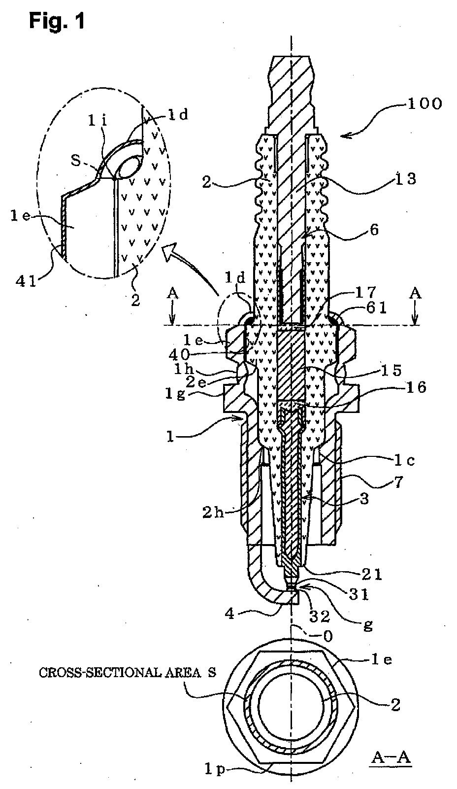
- FIG. 1 shows a spark plug 100 according to an embodiment of the present invention.
- the spark plug 100 includes a tubular metallic shell 1; an insulator 2 fitted into the metallic shell 1 such that a front end portion 21 projects from the metallic shell 1; a center electrode 3 provided in the insulator 2 such that a noble-metal discharge portion 31 formed on its front end projects from the insulator 2; and a ground electrode 4, one end thereof being joined to the metallic shell 1 by means of welding or the like, the other end portion thereof being bent such that its side surface faces the discharge portion 31 of the center electrode 3.
- a noble-metal discharge portion 32 is formed on the ground electrode 4 in opposition to the noble-metal discharge portion 31.
- the noble-metal discharge portion 31 and the noble-metal discharge portion 32 form a spark discharge gap g therebetween.
- the insulator 2 is formed from a ceramic sintered body such as alumina or aluminum nitride.
- the insulator 2 has a through-hole 6 formed therein along its axial direction so as to receive the center electrode 3.
- a metallic terminal member 13 is fixedly inserted into one end portion of the through-hole 6, whereas the center electrode 3 is fixedly inserted into the other end portion of the thorough-hole 6.
- a resistor 15 is disposed within the through-hole 6 between the metallic terminal member 13 and the center electrode 3. Opposite end portions of the resistor 15 are electrically connected to the center electrode 3 and the metallic terminal member 13 via conductive glass seal layers 16 and 17, respectively.
- a flange-like protrusion 2e is formed at a central portion of the insulator 2.
- the metallic shell 1 is formed into a tubular shape from carbon steel and serves as a housing of the spark plug 100.
- a male-threaded portion 7 and two protrusions are formed on the outer circumferential surface of the metallic shell 1 and adapted to mount the spark plug 100 on an unillustrated engine block.
- a flange-like gas seal portion 1g is formed adjacent to the rear side of the male-threaded portion 7, and a tool engagement portion 1e with which a tool such as a spanner or wrench is engaged when the metallic shell 1 is to be mounted is formed on the rear side relative to the gas seal portion 1g.
- a thin-walled portion 1h is formed between the tool engagement portion 1e and the gas seal portion 1g. The wall of the thin-walled portion 1h is thinner than that of the tool engagement portion 1e and that of the gas seal portion 1g.
- the tool engagement portion 1e has a plurality of pairs of mutually parallel tool engagement faces extending in parallel with the axis O and arranged circumferentially.
- the tool engagement portion 1e When the tool engagement portion 1e is to assume a regular hexagonal cross section, the tool engagement portion 1e has three pairs of the tool engagement faces. Alternatively, the tool engagement portion 1e may have 12 pairs of the mutually parallel tool engagement faces.
- the cross section of the tool engagement portion 1e assumes a shape obtained by shifting two superposed regular hexagonal shapes about the axis O by 30°. In either case, when the opposite side-to-side dimension ⁇ of the tool engagement portion 1e is represented by the distance between opposite sides of the hexagonal cross section, the opposite side-to-side dimension ⁇ of the tool engagement portion 1e is not greater than 14 mm.
- An insulator insertion hole 40 of a metallic shell 1 into which the flange-like protrusion 2e of the insulator 2 is inserted has an inside diameter of 8-12 mm.
- a steel material is selected such that, when S represents the cross-sectional area of the metallic shell 1 (the cross-sectional area of the crimped portion) as measured on a plane (A-A) perpendicularly intersecting the axis O at a position 1i where the inner wall surface of the insulator insertion hole 40 transitions to the inner wall surface of the crimped portion 1d with respect to the direction of the axis O of the metallic shell 1, the cross-sectional area S of the crimped portion and the carbon content of a steel material used to form the metallic shell 1 satisfy either of the following conditions A and B:
- the insulator 2 is pressed toward the front side while being inserted in the metallic shell 1, and then the opening edge of the metallic shell 1 is crimped inward toward the packing 61 to thereby form the crimped portion 1d, whereby the metallic shell 1 is firmly joined to the insulator 2.
- This crimping is performed by means of hot crimping as mentioned previously.
- an unillustrated gasket is fitted to a rear end part of the male-threaded portion 7 of the metallic shell 1 in such a manner as to abut the front end face of the gas seal portion 1g.
- the entire outer surface of the metallic shell I is covered with a nickel plating layer 41 for anticorrosiveness.
- the nickel plating layer 41 is formed by a known electroplating process and has a thickness of, for example, about 3-15 ⁇ m (as measured on a tool engagement face of the tool engagement portion 1e). When the film thickness is less than 3 ⁇ m, sufficient anticorrosiveness may not be attained. By contrast, a film thickness in excess of 15 ⁇ m is unnecessarily thick in terms of attainment of anticorrosiveness and requires long plating time, thereby leading to an increase in cost. Additionally, when the insulator 2 is to be joined by a crimping process, which will be described later, plating is likely to exfoliate at a portion subjected to crimping deformation.
- the nickel plating layer 41 is formed on the metallic shell 1 by a known electroplating process.
- the insulator 2 having the center electrode 3, the conductive glass seal layers 16 and 17, the resistor 15, and the metallic terminal member 13 inserted into the through-hole 6 is inserted into the metallic shell 1 from an opening portion located on the rear side of the insulator insertion hole 40 until an engagement portion 2h of the insulator 2 and an engagement portion 1c of the metallic shell 1 are joined via a thread packing (not shown) (see FIG. 1 for these members).
- the thread packing 61 is inserted into the metallic shell 1 from the insertion opening portion and disposed in place.
- a portion to be crimped of the metallic shell 1 is crimped toward the insulator 2 via the thread packing 61, thereby joining the metallic shell 1 and the insulator 2.
- This crimping process employs hot crimping.
- Step (a) of FIG. 2 a front end portion of the metallic shell 1 is inserted into a setting hole 110a of a crimping base 110 such that the flange-like gas seal portion 1g formed on the metallic shell 1 resets on the opening periphery of the setting hole 110a.
- the crimped portion 1d of the metallic shell 1 in FIG. 1 assumes a cylindrical form before crimping, and the cylindrical portion is called a portion-to-be-crimped 1d'.
- the crimping die 111 is fitted to the metallic shell 1 from above.
- a concave crimping action surface 111p corresponding to the crimped portion 1d (FIG. 1) is formed on a portion of the crimping die 111 which abuts the portion-to-be-crimped 1d'.
- an axial compressive force directed toward the crimping base 110 is applied to the crimping die 111 so as to move the crimping die 111 toward the crimping base 110; as a result, the portion-to-be-crimped 1d' is compressed while being curved radially inward along the crimping action surface 11 1p.
- Step (b) the metallic shell 1 and the insulator 2 are firmly joined through crimping.
- Application of a compressive force combined with supply of electricity causes the thin-walled portion 1h formed between the gas seal portion 1g and the tool engagement portion 1e to be heated and plastically deformed in a compressed condition, as shown in FIG. 2.
- Shutting off electricity while the compressed state is maintained causes the thermally expanded thin-walled portion 1h to be cooled, thereby enhancing a fastening force. Since the thin-walled portion 1h is compressed while its ends joined to the tool engagement portion 1e and the gas seal portion 1g are restrained, the thin-walled portion 1h undergoes a kind of barrel-like deformation. After completion of hot crimping, the thin-walled portion 1h assumes a biconvex section whose inner and outer surfaces are swollen in a radially convex condition.
- Spark plugs 200 and 300 shown in FIGS. 3 and 4 were fabricated for test use. These spark plugs 200 and 300 are configured in a manner similar to that of the spark plug 100 of FIG. 1 except that the noble-metal discharge portions 31 and 32 are omitted. Structural features conceptually common to those of the spark plug 100 of FIG. 1 are denoted by common reference numerals (typical structural features are selected and assigned reference numerals).
- the crimped portion 1d is formed by means of hot crimping.
- the spark plugs 200 and 300 have the following features:
- the carbon content of a carbon steel used to form the metallic shell 1 was varied in the range of 0.05% by weight to 0.50% by weight. These spark plugs 200 and 300 were subjected to a hot airtightness test under the conditions below and measured for air leakage from the crimped portion 1d (portion filled with the filler material 61).
- test results are shown for individual tested spark plugs.
- 1000 spark plugs (test quantity n is 1000) for each carbon content were tested for quenching crack in the thin-walled portion 1h under the following condition: after hot crimping, the spark plugs were subjected to forced cooling by means of fan cooling. Criteria were as follows: good (O): none of tested spark plugs suffers quenching crack; and defective ( ⁇ ): even a single tested spark plug suffers quenching crack.
- the spark plugs 200 which satisfy the carbon content range of condition B and the spark pugs 300 which satisfy the carbon content range of condition A show no air leakage at 150°C, thereby indicating that gastightness is maintained. Also, as is apparent from the test results, the spark plugs 200 and 300 that use a carbon steel of a carbon content (0.5% by weight) in excess of 0.45% by weight, which is the upper limit of the present invention, are apt to suffer quenching crack in the thin-walled portion 1h.
Landscapes
- Engineering & Computer Science (AREA)
- Manufacturing & Machinery (AREA)
- Spark Plugs (AREA)
Abstract
Description
characterized in that:
- 100, 200, 300, 400: spark plugs
- 1: metallic shell
- 1d: crimped portion
- 1e: tool engagement portion
- 1h: thin-walled portion
- 2: insulator
- 3: center electrode
- 4: ground electrode
- g: spark discharge gap
- 7: male-threaded portion
- 40: insulator insertion hole
Cross-sectional area S of crimped portion: 25-35 mm2
(satisfying condition B);
Inside diameter of insulator insertion hole 40: 11.2
mm;
Hot crimping condition: applied pressure about 2-2.5 ton;
and
Temperature: 850°C as measured at thin-walled portion
1h by means of radiation thermometer.
Cross-sectional area S of crimped portion: 13-25 mm2
(satisfying condition A);
Inside diameter of insulator insertion hole 40: 10
mm;
Hot crimping condition: applied pressure about 1.5-2.0 ton;
and
Temperature: 850°C as measured at thin-walled portion
1h by means of radiation thermometer.
plug

| Carbon content | Electrolytic nickel plating | Electrogalvanization |
| Quantity suffering cracking | Quantity suffering cracking | |
| 0.05 | 0 | 0 |
| 0.1 | 0 | 0 |
| 0.15 | 0 | 9 |
| 0.20 | 0 | 14 |
| 0.30 | 0 | 20 |
| 0.40 | 0 | 25 |
| 0.50 | 0 | 31 |
Claims (5)
- A spark plug comprising a rodlike center electrode (3), a rodlike insulator (2) surrounding said center electrode (3) and having a protrusion (2e) at a central portion thereof, a metallic shell (1) assuming an open-ended, tubular shape and surrounding said insulator (2), and a ground electrode (4), a first end of said ground electrode (4) being joined to said metallic shell (1) and a second end of said ground electrode (4) facing said center electrode (3) to thereby define a spark discharge gap (g), and wherein:an insulator insertion hole (40) into which said protrusion (2e) of said insulator (2) is inserted is formed in said metallic shell (1) while extending in a direction of an axis (O); when a side toward said spark discharge gap (g) with respect to the direction of said axis (O) is taken as a front side, a rear end portion of said metallic shell (1) is hot-crimped toward said insulator (2) to thereby be formed into a curved, crimped portion (1d);two protrusions (1e and 1g) and a thin-walled portion (1h) are formed on an outer surface of said metallic shell (1) such that said thin-walled portion (1h) is located between said two protrusions (1e and 1g), is thinner than said two protrusions (1e and 1g), and assumes a section whose inner and outer surfaces are swollen in a radially convex condition with respect to said axis (O) and such that one of said protrusions (1e and 1g) is formed to be located adjacent to and on the front side of said crimped portion (1d); andan inside diameter of said insulator insertion hole (40) of said metallic shell (1) is 8-12 mm as measured at a position (1i) where an inner wall surface of said insulator insertion hole (40) transitions to an inner wall surface of said crimped portion (1d) with respect to the direction of said axis (O) of said metallic shell (1); and a cross-sectional area S of said metallic shell (1) as measured when said metallic shell (1) is cut at said position (1i) by a plane perpendicular to said axis (O), and a carbon content of a steel material used to form said metallic shell (1) satisfy either of the following conditions A and B:condition A: 15≤S<25 mm2 and a carbon content of 0.20%-0.45% by weight; andcondition B: 25≤S<35 mm2 and a carbon content of 0.15%-0.45% by weight.
- A spark plug as defined in claim 1, wherein a nickel plating layer is formed on said metallic shell (1) so as to serve as an anticorrosive film.
- A method for manufacturing a spark plug comprising:a rodlike center electrode (3);a rodlike insulator (2) having a through-hole (6) formed therein along a direction of an axis (O) and having a protrusion (2e) at a central portion thereof, said center electrode (3) being disposed in said through-hole (6);a metallic shell (1) surrounding said insulator (2), having an insulator insertion hole (40) formed therein so as to accommodate said protrusion (2e) of said insulator (2), assuming an open-ended, tubular shape, andhaving two protrusions (1e and 1g) and a thin-walled portion (1h) formed on an outer surface thereof at a central portion thereof with respect to the direction of said axis (O), the thin-walled portion (1h) being located between said two protrusions (1e and 1g) and being thinner than said two protrusions (1e and 1g); anda ground electrode (4), a first end of said ground electrode (4) being joined to said metallic shell (1) and a second end of said ground electrode (4) facing said center electrode (3) to thereby define a spark discharge gap (g);with a side toward said spark discharge gap (g) with respect to the direction of said axis (O) being taken as a front side, a rear end portion of said metallic shell (1) adjacent to one of said two protrusions (1e and 1g) being crimped toward said insulator (2) to thereby be formed into a curved, crimped portion (1d);said method comprising:a metallic-shell formation step for forming said metallic shell (1) such that an inside diameter of said insulator insertion hole (40) of said metallic shell (1) formed from a steel material having a carbon content of 0.20%-0.45% by weight is 8-12 mm as measured at a position (1i) where an inner wall surface of said insulator insertion hole (40) transitions to an inner wall surface of said crimped portion (1d) with respect to the direction of said axis (O) of said metallic shell (1), anda cross-sectional area S of said metallic shell (1) as measured when said metallic shell (1) is cut at said position (1i) by a plane perpendicular to said axis (O) satisfies 15≤S<25 mm2;an insulator disposition step for disposing said insulator (2) in said insulator insertion hole (40) of said metallic shell (1); anda hot crimping step for curving radially inward a portion-to-be-crimped (1d') located at a rear end portion of said metallic shell (1) while electricity is supplied to said metallic shell (1), so as to form said crimped portion (1d), and forming said thin-walled portion (1h) while electricity-effected heating is performed.
- A method for manufacturing a spark plug comprising:a rodlike center electrode (3);a rodlike insulator (2) having a through-hole (6) formed therein along a direction of an axis (O) and having a protrusion (2e) at a central portion thereof, said center electrode (3) being disposed in said through-hole (6);a metallic shell (1) surrounding said insulator (2), having an insulator insertion hole (40) formed therein so as to accommodate said protrusion (2e) of said insulator (2), assuming an open-ended, tubular shape, andhaving two protrusions (1e and 1g) and a thin-walled portion (1h) formed on an outer surface thereof at a central portion thereof with respect to the direction of said axis (O), said thin-walled portion (1h) being located between said two protrusions (1e and 1g), being thinner than said two protrusions (1e and 1g), and assuming a section whose inner and outer surfaces are swollen in a radially convex condition with respect to said axis (O); anda ground electrode (4), a first end of said ground electrode (4) being joined to said metallic shell (1) and a second end of said ground electrode (4) facing said center electrode (3) to thereby define a spark discharge gap (g);with a side toward said spark discharge gap (g) with respect to the direction of said axis (O) being taken as a front side, a rear end portion of said metallic shell (1) adjacent to one of said two protrusions (1e and 1g) being crimped toward said insulator (2) to thereby be formed into a curved, crimped portion (1d);said method comprising:a metallic-shell formation step for forming said metallic shell (1) such that an inside diameter of said insulator insertion hole (40) of said metallic shell (1) formed from a steel material having a carbon content of 0.15%-0.45% by weight is 8-12 mm as measured at a position (1i) where an inner wall surface of said insulator insertion hole (40) transitions to an inner wall surface of said crimped portion (1d) with respect to the direction of said axis (O) of said metallic shell (1), anda cross-sectional area S of said metallic shell (1) as measured when said metallic shell (1) is cut at said position (1i) by a plane perpendicular to said axis (O) satisfies 25≤S<35 mm2;an insulator disposition step for disposing said insulator (2) in said insulator insertion hole (40) of said metallic shell (1); anda hot crimping step for curving radially inward a portion-to-be-crimped (1d') located at a rear end portion of said metallic shell (1) while electricity is supplied to said metallic shell (1), so as to form said crimped portion (1d), and forming, while electricity-effected heating is performed, said thin-walled portion (1h) assuming a section whose inner and outer surfaces are swollen in a radially convex condition with respect to said axis (O).
- A method according to claim 3 or 4 for manufacturing a spark plug, further comprising a step for forming a nickel plating layer on the outer surface of said metallic shell (1), said step intervening between said metallic-shell formation step and said insulator disposition step.
Applications Claiming Priority (2)
| Application Number | Priority Date | Filing Date | Title |
|---|---|---|---|
| JP2001401428 | 2001-12-28 | ||
| JP2001401428 | 2001-12-28 |
Publications (3)
| Publication Number | Publication Date |
|---|---|
| EP1324446A2 true EP1324446A2 (en) | 2003-07-02 |
| EP1324446A3 EP1324446A3 (en) | 2006-05-17 |
| EP1324446B1 EP1324446B1 (en) | 2007-10-31 |
Family
ID=19189774
Family Applications (1)
| Application Number | Title | Priority Date | Filing Date |
|---|---|---|---|
| EP02258868A Expired - Lifetime EP1324446B1 (en) | 2001-12-28 | 2002-12-23 | Spark plug and method for manufacturing the spark plug |
Country Status (3)
| Country | Link |
|---|---|
| US (1) | US6849995B2 (en) |
| EP (1) | EP1324446B1 (en) |
| DE (1) | DE60223225T2 (en) |
Cited By (6)
| Publication number | Priority date | Publication date | Assignee | Title |
|---|---|---|---|---|
| US7400081B2 (en) * | 2004-07-27 | 2008-07-15 | Denso Corporation | Compact spark plug with high gas tightness |
| CN102598441A (en) * | 2009-08-26 | 2012-07-18 | 日本特殊陶业株式会社 | Spark plug for internal combustion engine and method for manufacturing same |
| CN103250310A (en) * | 2010-12-07 | 2013-08-14 | 日本特殊陶业株式会社 | Spark plug |
| EP2541703A4 (en) * | 2010-02-26 | 2014-07-09 | Ngk Spark Plug Co | IGNITION CANDLE |
| EP2395614A3 (en) * | 2010-06-11 | 2014-07-23 | Ngk Spark Plug Co., Ltd. | Spark plug and manufacturing method thereof |
| EP2634872A4 (en) * | 2010-10-29 | 2015-02-25 | Ngk Spark Plug Co | Spark plug |
Families Citing this family (11)
| Publication number | Priority date | Publication date | Assignee | Title |
|---|---|---|---|---|
| JP4658871B2 (en) * | 2005-09-01 | 2011-03-23 | 日本特殊陶業株式会社 | Spark plug |
| US7772751B2 (en) * | 2006-03-13 | 2010-08-10 | Ngk Spark Plug Co., Ltd. | Spark plug having a rear-end portion of a threaded portion that has a higher hardness than a crimp portion and method of manufacturing the same |
| JP4351272B2 (en) * | 2006-09-07 | 2009-10-28 | 日本特殊陶業株式会社 | Spark plug |
| EP1976078B1 (en) | 2007-03-30 | 2011-09-14 | NGK Spark Plug Company Limited | Spark plug for internal combustion engine |
| JP4728437B1 (en) * | 2010-03-10 | 2011-07-20 | 日本特殊陶業株式会社 | Spark plug, metal shell for spark plug, and method for manufacturing spark plug |
| JP4906948B2 (en) | 2010-08-26 | 2012-03-28 | 日本特殊陶業株式会社 | Spark plug |
| US8568181B2 (en) * | 2010-10-28 | 2013-10-29 | Fram Group Ip Llc | Spark plug with undercut insulator |
| JP5960869B1 (en) * | 2015-04-17 | 2016-08-02 | 日本特殊陶業株式会社 | Spark plug |
| JP6817252B2 (en) * | 2018-06-22 | 2021-01-20 | 日本特殊陶業株式会社 | Spark plug |
| DE102019203913A1 (en) * | 2019-03-21 | 2020-09-24 | Robert Bosch Gmbh | Spark plug housing, spark plug and method of making a spark plug |
| US11489316B2 (en) * | 2019-04-11 | 2022-11-01 | Federal-Mogul Ignition Llc | Spark plug shell and method of manufacture |
Family Cites Families (8)
| Publication number | Priority date | Publication date | Assignee | Title |
|---|---|---|---|---|
| US2308968A (en) * | 1941-05-16 | 1943-01-19 | Firestone Tire & Rubber Co | Spark plug crimping method and apparatus |
| JPS63266046A (en) | 1986-12-10 | 1988-11-02 | Ngk Spark Plug Co Ltd | Steel for metallic fixture of essentially spark plug use and its production |
| JPS63148585A (en) | 1986-12-10 | 1988-06-21 | 日本特殊陶業株式会社 | Small size ignition plug |
| JPH0270019A (en) | 1988-09-05 | 1990-03-08 | Ngk Spark Plug Co Ltd | Production of steel for ignition plug body fitting |
| JP3421075B2 (en) * | 1993-03-24 | 2003-06-30 | 日本発条株式会社 | Method for caulking thermoplastic resin member and fastener |
| JP3502936B2 (en) * | 1999-01-21 | 2004-03-02 | 日本特殊陶業株式会社 | Spark plug and method of manufacturing the same |
| JP2000215963A (en) * | 1999-01-25 | 2000-08-04 | Ngk Spark Plug Co Ltd | Spark plug manufacturing equipment and spark plug manufacturing method |
| DE60224915T2 (en) * | 2001-12-28 | 2009-01-29 | NGK Spark Plug Co., Ltd., Nagoya-shi | Spark plug and method of manufacturing the spark plug |
-
2002
- 2002-12-23 DE DE60223225T patent/DE60223225T2/en not_active Expired - Lifetime
- 2002-12-23 EP EP02258868A patent/EP1324446B1/en not_active Expired - Lifetime
- 2002-12-24 US US10/327,061 patent/US6849995B2/en not_active Expired - Lifetime
Cited By (10)
| Publication number | Priority date | Publication date | Assignee | Title |
|---|---|---|---|---|
| US7400081B2 (en) * | 2004-07-27 | 2008-07-15 | Denso Corporation | Compact spark plug with high gas tightness |
| CN102598441A (en) * | 2009-08-26 | 2012-07-18 | 日本特殊陶业株式会社 | Spark plug for internal combustion engine and method for manufacturing same |
| CN102598441B (en) * | 2009-08-26 | 2013-06-26 | 日本特殊陶业株式会社 | Spark plug for internal combustion engine and manufacturing method of spark plug |
| EP2472682A4 (en) * | 2009-08-26 | 2014-04-16 | Ngk Spark Plug Co | IGNITION CANDLE FOR INTERNAL COMBUSTION ENGINE AND METHOD OF MANUFACTURING THE SAME |
| EP2541703A4 (en) * | 2010-02-26 | 2014-07-09 | Ngk Spark Plug Co | IGNITION CANDLE |
| EP2395614A3 (en) * | 2010-06-11 | 2014-07-23 | Ngk Spark Plug Co., Ltd. | Spark plug and manufacturing method thereof |
| EP2634872A4 (en) * | 2010-10-29 | 2015-02-25 | Ngk Spark Plug Co | Spark plug |
| CN103250310A (en) * | 2010-12-07 | 2013-08-14 | 日本特殊陶业株式会社 | Spark plug |
| CN103250310B (en) * | 2010-12-07 | 2014-12-17 | 日本特殊陶业株式会社 | Spark plug |
| US9130355B2 (en) | 2010-12-07 | 2015-09-08 | Ngk Spark Plug Co., Ltd. | Spark plug |
Also Published As
| Publication number | Publication date |
|---|---|
| DE60223225T2 (en) | 2008-07-31 |
| US6849995B2 (en) | 2005-02-01 |
| US20030168955A1 (en) | 2003-09-11 |
| EP1324446B1 (en) | 2007-10-31 |
| EP1324446A3 (en) | 2006-05-17 |
| DE60223225D1 (en) | 2007-12-13 |
Similar Documents
| Publication | Publication Date | Title |
|---|---|---|
| EP1324446B1 (en) | Spark plug and method for manufacturing the spark plug | |
| EP2200133B1 (en) | Spark plug | |
| EP1022829A1 (en) | Spark plug and method of manufacturing the same | |
| US7573185B2 (en) | Small diameter/long reach spark plug with improved insulator design | |
| JPH05335066A (en) | Spark plug for internal combustion engine | |
| US6759795B2 (en) | Spark plug | |
| US7772751B2 (en) | Spark plug having a rear-end portion of a threaded portion that has a higher hardness than a crimp portion and method of manufacturing the same | |
| EP2073327B1 (en) | Spark plug for internal combustion engine | |
| US7400081B2 (en) | Compact spark plug with high gas tightness | |
| JP4685817B2 (en) | Spark plug and manufacturing method thereof | |
| JP2004134120A (en) | Spark plug | |
| US6809463B2 (en) | Spark plug and method for manufacturing the spark plug | |
| US6909226B2 (en) | Method for manufacturing spark plug, and spark plug | |
| JP2022172777A (en) | Spark plug | |
| EP1641093B1 (en) | Spark plug | |
| US8531094B2 (en) | Spark plug having self-cleaning of carbon deposits | |
| JP2003257583A (en) | Spark plug | |
| US7049734B2 (en) | Structure of spark plug achieving high degree of air-tightness | |
| US7994694B2 (en) | Spark plug for internal combustion engine | |
| JP2003257584A (en) | Spark plug | |
| JP2003303661A (en) | Spark plug for internal combustion engine and method of manufacturing the same |
Legal Events
| Date | Code | Title | Description |
|---|---|---|---|
| PUAI | Public reference made under article 153(3) epc to a published international application that has entered the european phase |
Free format text: ORIGINAL CODE: 0009012 |
|
| AK | Designated contracting states |
Designated state(s): AT BE BG CH CY CZ DE DK EE ES FI FR GB GR IE IT LI LU MC NL PT SE SI SK TR |
|
| AX | Request for extension of the european patent |
Extension state: AL LT LV MK RO |
|
| PUAL | Search report despatched |
Free format text: ORIGINAL CODE: 0009013 |
|
| AK | Designated contracting states |
Kind code of ref document: A3 Designated state(s): AT BE BG CH CY CZ DE DK EE ES FI FR GB GR IE IT LI LU MC NL PT SE SI SK TR |
|
| AX | Request for extension of the european patent |
Extension state: AL LT LV MK RO |
|
| 17P | Request for examination filed |
Effective date: 20060523 |
|
| 17Q | First examination report despatched |
Effective date: 20061130 |
|
| AKX | Designation fees paid |
Designated state(s): DE FR GB |
|
| GRAP | Despatch of communication of intention to grant a patent |
Free format text: ORIGINAL CODE: EPIDOSNIGR1 |
|
| GRAS | Grant fee paid |
Free format text: ORIGINAL CODE: EPIDOSNIGR3 |
|
| GRAA | (expected) grant |
Free format text: ORIGINAL CODE: 0009210 |
|
| AK | Designated contracting states |
Kind code of ref document: B1 Designated state(s): DE FR GB |
|
| REG | Reference to a national code |
Ref country code: GB Ref legal event code: FG4D |
|
| REF | Corresponds to: |
Ref document number: 60223225 Country of ref document: DE Date of ref document: 20071213 Kind code of ref document: P |
|
| ET | Fr: translation filed | ||
| PLBE | No opposition filed within time limit |
Free format text: ORIGINAL CODE: 0009261 |
|
| STAA | Information on the status of an ep patent application or granted ep patent |
Free format text: STATUS: NO OPPOSITION FILED WITHIN TIME LIMIT |
|
| 26N | No opposition filed |
Effective date: 20080801 |
|
| PGFP | Annual fee paid to national office [announced via postgrant information from national office to epo] |
Ref country code: GB Payment date: 20101222 Year of fee payment: 9 |
|
| GBPC | Gb: european patent ceased through non-payment of renewal fee |
Effective date: 20111223 |
|
| PG25 | Lapsed in a contracting state [announced via postgrant information from national office to epo] |
Ref country code: GB Free format text: LAPSE BECAUSE OF NON-PAYMENT OF DUE FEES Effective date: 20111223 |
|
| REG | Reference to a national code |
Ref country code: FR Ref legal event code: PLFP Year of fee payment: 14 |
|
| REG | Reference to a national code |
Ref country code: FR Ref legal event code: PLFP Year of fee payment: 15 |
|
| REG | Reference to a national code |
Ref country code: DE Ref legal event code: R082 Ref document number: 60223225 Country of ref document: DE Representative=s name: KLUNKER IP PATENTANWAELTE PARTG MBB, DE |
|
| REG | Reference to a national code |
Ref country code: FR Ref legal event code: PLFP Year of fee payment: 16 |
|
| PGFP | Annual fee paid to national office [announced via postgrant information from national office to epo] |
Ref country code: FR Payment date: 20191115 Year of fee payment: 18 |
|
| PG25 | Lapsed in a contracting state [announced via postgrant information from national office to epo] |
Ref country code: FR Free format text: LAPSE BECAUSE OF NON-PAYMENT OF DUE FEES Effective date: 20201231 |
|
| PGFP | Annual fee paid to national office [announced via postgrant information from national office to epo] |
Ref country code: DE Payment date: 20211102 Year of fee payment: 20 |
|
| REG | Reference to a national code |
Ref country code: DE Ref legal event code: R071 Ref document number: 60223225 Country of ref document: DE |