EP1324330A1 - Disk player - Google Patents
Disk player Download PDFInfo
- Publication number
- EP1324330A1 EP1324330A1 EP01972478A EP01972478A EP1324330A1 EP 1324330 A1 EP1324330 A1 EP 1324330A1 EP 01972478 A EP01972478 A EP 01972478A EP 01972478 A EP01972478 A EP 01972478A EP 1324330 A1 EP1324330 A1 EP 1324330A1
- Authority
- EP
- European Patent Office
- Prior art keywords
- disk
- arm
- startup
- cam
- shift bar
- Prior art date
- Legal status (The legal status is an assumption and is not a legal conclusion. Google has not performed a legal analysis and makes no representation as to the accuracy of the status listed.)
- Granted
Links
- 230000033001 locomotion Effects 0.000 claims description 35
- 238000003780 insertion Methods 0.000 description 5
- 230000037431 insertion Effects 0.000 description 5
- 238000010276 construction Methods 0.000 description 4
- 230000001939 inductive effect Effects 0.000 description 4
- 230000003287 optical effect Effects 0.000 description 3
- 238000001514 detection method Methods 0.000 description 2
- 230000002093 peripheral effect Effects 0.000 description 2
- 238000005452 bending Methods 0.000 description 1
- 230000005540 biological transmission Effects 0.000 description 1
- 230000000593 degrading effect Effects 0.000 description 1
- 238000010348 incorporation Methods 0.000 description 1
- 230000005764 inhibitory process Effects 0.000 description 1
- 230000010354 integration Effects 0.000 description 1
- 230000009545 invasion Effects 0.000 description 1
- 238000004519 manufacturing process Methods 0.000 description 1
Images



Classifications
-
- G—PHYSICS
- G11—INFORMATION STORAGE
- G11B—INFORMATION STORAGE BASED ON RELATIVE MOVEMENT BETWEEN RECORD CARRIER AND TRANSDUCER
- G11B17/00—Guiding record carriers not specifically of filamentary or web form, or of supports therefor
- G11B17/02—Details
- G11B17/04—Feeding or guiding single record carrier to or from transducer unit
- G11B17/05—Feeding or guiding single record carrier to or from transducer unit specially adapted for discs not contained within cartridges
- G11B17/051—Direct insertion, i.e. without external loading means
- G11B17/0515—Direct insertion, i.e. without external loading means adapted for discs of different sizes
-
- G—PHYSICS
- G11—INFORMATION STORAGE
- G11B—INFORMATION STORAGE BASED ON RELATIVE MOVEMENT BETWEEN RECORD CARRIER AND TRANSDUCER
- G11B17/00—Guiding record carriers not specifically of filamentary or web form, or of supports therefor
- G11B17/02—Details
- G11B17/04—Feeding or guiding single record carrier to or from transducer unit
- G11B17/05—Feeding or guiding single record carrier to or from transducer unit specially adapted for discs not contained within cartridges
- G11B17/053—Indirect insertion, i.e. with external loading means
- G11B17/056—Indirect insertion, i.e. with external loading means with sliding loading means
- G11B17/0565—Indirect insertion, i.e. with external loading means with sliding loading means adapted for discs of different sizes
-
- G—PHYSICS
- G11—INFORMATION STORAGE
- G11B—INFORMATION STORAGE BASED ON RELATIVE MOVEMENT BETWEEN RECORD CARRIER AND TRANSDUCER
- G11B17/00—Guiding record carriers not specifically of filamentary or web form, or of supports therefor
- G11B17/02—Details
- G11B17/04—Feeding or guiding single record carrier to or from transducer unit
- G11B17/057—Feeding or guiding single record carrier to or from transducer unit specially adapted for handling both discs contained within cartridges and discs not contained within cartridges
Definitions
- the present invention relates to a disk player for reproducing an optical disk signal including CD, LD, DVD, etc. More particularly, the present invention relates to a disk clamping mechanism automatically compatible to both of a large diameter disk of 12 cm in diameter and a small diameter disk of 8 cm in diameter.
- Japanese Patent No. 2955116 there is disclosed a disk loading device compatible with two types of disks having large and small diameters.
- a rack gear 4 and a side face of a shift plate 11 are vertically arranged on the faces of a CD 12 and a CD 13, and thus, the dimensions in this direction cannot be reduced any more.
- a mechanism including a stopper arm 8, a lock arm 9, and a stopper arm spring 8a inhibits the dimensions in the thickness direction vertical to the faces of the CD 12 and the CD 13 and reduction in the number of parts.
- a disk player comprises: a carriage mechanism for basically feeding a selected one of the small diameter and large diameter disks to a turntable; and a clamping mechanism for compressing the disk to the turntable.
- the disk player comprises: a selection arm which abuts against the disk and which can be turned according to its disk diameter; a shift bar which abuts against the disk and which can be moved in a disk feeding direction; a startup arm which is engaged with the shift bar and which turns the shift bar to be interlocked so as to be movable in the disk feeding direction; inscribed cam means in which the startup arm is coupled with a clamp arm of the clamp mechanism via a cam, thereby restricting turning, the cam means being capable of engagingly locking the startup arm at a different position depending on the scale of the diameter of the disk to be fed; first biasing means for biasing the shift bar in a direction opposite to the disk feeding direction; and second biasing means for biasing the startup arm, thereby holding the arm at a different engagingly locked position of the inscribed cam.
- the disk moving the shift bar to be pushed against the biasing force of the first biasing means turns the selection arm and controls the startup arm. Then, the shift bar is restricted by the startup arm held at any of the engagingly locked position of the inscribed cam, whereby the centers of the disks having their different diameters are positioned at the same position.
- the first biasing means and the second biasing means are constructed to provide one tensile coil sprint in a tensile manner between the startup arm and the clamp arm.
- a swivel shaft is slidably guided to the clamp arm by a straight groove provided at a right angle relevant to the advancement direction of the disk.
- a cam follower pin erected at a position spaced from the swivel shaft of the startup arm introduces swiveling of the startup arm while a slide contact is maintained with either of first and second cam portions provided at the inscribed cam corresponding to a respective one of the large and small diameters of the disk to be fed by the biasing force of the tensile coil spring.
- This cam follower pin is constrained to either of a first pocket and a second pocket provided at terminals of the first and the second cams, whereby movement of the startup bar is inhibited in cooperation with the swivel shaft restricted by the straight groove.
- the present invention is characterized in that movement from the first cam portion of the cam follower pin to a second cam portion is carried out in planar movement following a path defined by longitudinal movement of the shift bar moving in a disk feeding direction and transverse movement of the startup arm together with swinging movement of the selection arm in a cooperative manner, and these movements are not carried out by a specified guide groove which is mechanically formed.
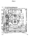
- FIG. 1 is a plan view showing a schematic internal mechanism when a disk player 10 according to the present invention is set at a standby position (a home position) , wherein a housing and a chassis are illustrated in a transparent manner in order to clearly show a hidden portion.
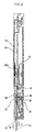
- FIG. 2 is an enlarged side view taken along the line 2-2 of FIG. 1.
- a direction in which when the disk is moved to be inserted denotes a forward direction (F direction), and movement in the opposite direction denotes a retracting direction (R direction).
- Reference numeral 11 denotes a clamping mechanism, wherein a center portion 15 of disks 14a, 14b (generally indicated by reference numeral 14) is aligned with the center of a turntable at a free end of the clamp arm 12 by the clamping action caused by a rotatably supported clamp ring 13.
- a shift bar 17 moved to be pushed by the disks 14a, 14b an erected piece 17a engaged with outer periphery edges C1, C2 of the disks 14a, 14b is formed to be folded at a right angle at both of the left and right ends.
- the shift bar 17 guides a long groove 18 punched at the clamp arm 12, can slide in the vertical direction in the figure (in the movement direction of the disk 14), is embedded in the shift bar 17, and guided forwardly or backwardly by two guide pins 17b fitted with the long groove 18 to be moved in parallel.
- connection pin 17c is erected at the center of two guide pins 17b embedded in the shift bar 17, and slidably engaged into the long hole 21 punched at the tip end of a startup arm 20.
- a swivel shaft 22 embedded in the startup arm 20 guides a straight groove 23 punched on the clamp arm 12, and is slidably supported in the transverse direction in the figure (a direction vertical to the movement direction of the disk 14).
- the startup arm 20 can be turned around the swivel shaft 22.
- a tensile coil spring 24 is provided in a tensile manner between the startup arm and the clamp arm 12. This spring is biased around the swivel shaft 22 in the clockwise direction in the figure.
- a cam follower pin 25 is embedded at a position spaced from the swivel shaft 22. Then, this cam follower pin abuts against a straight portion 26a formed in parallel to the straight groove 23 at the internal wall front edge of an inscribed cam 26 punched at the clamp arm 12; supports the biasing force of the tensile coil spring 24; and inhibits free turning movement of the startup arm 20.
- a top face guide plate 28 (refer to FIG. 2) of the carriage mechanism 27 brings the top face of the disk 14 into slide contact with the bottom face, and guides it in parallel to the face of the turntable 16.
- a roller 29 is provided at the bottom face of the top face guide plate 28, and a rotary shaft 30 is transversely provided relevant to the top face guide plate 28.
- the disk 14 is configured so as to be pinched in cooperation with the bottom face of the opposite top face guide face 28.
- a printed circuit board 32 including photo sensors 31a, 31b for sensing insertion and ejection of the disk 14 and for identifying whether the diameter of the disk is large or small in size.
- a drive motor 33 is started up to interlock a gear train 34 coupled with the rotary shaft 30 of the roller 29. Then, the roller 29 is rotated in a direction in which the disk 14 is fed to the turntable 16 (in the direction indicated by the arrow F).
- the slide plate 35 is supported so as to be slid in the forward or the backward direction (in the direction indicated by the arrow F-R) parallel to the movement direction of the disk along the bottom face of the drive board 40.
- the movement in the transverse and the vertical direction in a direction vertical to paper face) is restricted.
- the gear face of the slide rack 37 is made vertical to the disk face, whereby only the plate thickness of the slide rack 37 is included in dimensions in the vertical direction.
- a housing 51 can be thinly constructed.
- Either of the first link portion 44a and the second link portion 44b provided at the end of the startup arm 20 is opposed to an end 37a at the rear of the slide rack 37.
- Either of the first link portion 44a and the second link portion 44b is abutted against the end 37a of the slide rack 37 by swiveling operation of the startup arm 20.
- the slide rack 37 is relatively moved in the frontal side (in the direction indicated by the arrow R) on the slide plate 35, and the tooth portion 37b is moved to be pushed against a position geared with the drive pinion 39.
- a cam follower 48 punched at the tip end of a laterally extended plate sprint 46 abuts against a bent site 47b of a crank shaped cam groove 47 (indicated by double dotted chain line) punched on a drive board 40, and movement is inhibited.
- the slide rack 37 moved to be pushed by either of the first link portion 44a or the second link portion 44b relatively moves to the slide plate 35 against the biasing force while extending the tensile coil spring 38 provided in a tensile manner between the rack and the slide plate 35.
- the slide rack 37 compresses the cam follower 48 to be engaged into a recess 49 of the slide plate 35 by an action piece 45 while the tooth portion 37b is made proximal to the drive pinion 39.
- the slide rack releases inhibition of the bent site 47b, and causes the bent site to be advanced into an inductive groove 47a of a crank shaped cam groove 47.
- the cam follower 48 holds engagement with the recess 49 by constraining of the inductive groove 47a.
- a fixedly provided stopper 37c is engagingly locked with the cam follower 48.
- the tensile coil spring 38 is held in an extended state, a relative position to the slide plate 35 is fixed, and integrated movement is made.
- a cam follower (not shown) engaged with a respective one of a plurality of cams 35a, 35b, 35c (refer to FIG. 4) formed on the slide plate 35 is interlocked with another by reciprocating action of the slide plate 35. Then, movements of the clamp mechanism 11, the turntable 16 and the top face guide plate 28, and the roller 29 lying in a linkage relationship with this top face guide plate are controlled.
- Reference numeral 50 denotes a selection arm, wherein its substantial center of the length is turnably supported around a swivel shaft 52 embedded in a housing 51 for housing a board 40, and is biased by a tensile coil spring 52a provided in a tensile manner between the arm and the housing 51 in the counterclockwise direction in the figure.
- a first end 50a formed by bending one end of the selection arm 50 penetrates a notch 28a provided at the top face guide plate 28, and extends at the bottom face side of the top face guide plate 28.
- This first end engages with only an outer periphery edge C2 of a large diameter disk 14b to be inserted, and does not interfere with an outer periphery edge C1 of a small diameter disk 14a.
- the another second end 50b is arranged at a position opposed to the first linkage portion 44a of the startup arm 20.
- the startup arm 20 in which the cam follower pin 25 reaches the first engagement position 43b, and turning movement is inhibited, restricts the shift bar 17, and inhibits movement of the small diameter disk 14a.
- the biasing force of the tensile coil spring 24 locks the cam follower pin 25 at the retracted position of a pocket 43c, determines the position of the shift bar 17, and positions the small diameter disk 14a.
- the small diameter disk 14a subjected to the centering adjustment action caused by the conical face of a tapered boss face 16a at the center of the turntable 16 moves to the aligned position, whereby the outer periphery edge C1 of the small diameter disk 14a is spaced from the erected piece 17a.
- the small diameter disk 14a is released from its abutment state in the foregoing pushing and the moving operation, and stable rotation can be obtained.
- the slide rack 37 is moved to be pushed against the biasing force of the tensile coil spring 38 up to the position at which the tooth portion 37b is geared with the drive pinion 39. Then, the relative position of the slide rack 37 is moved to the slide plate 35 braked by abutment of the cam follower 48 against the bent site 47b at the inlet of the inductive groove 47a of the crank shaped cam groove 47.
- the action piece 45 engages the cam follower 48 into the recess 49 at a position at which driving by the drive pinion 39 is started, and integrates the slide plate 35. Then, the slide rack moves in the frontal side (in the direction indicated by the arrow R) while constraining the cam follower 48 along the inductive groove 47a.
- the cam 35a provided at the slide plate 35 is functioned by sliding operation of the slide plate 35.
- the small diameter disk 14a is aligned by being compressed on a tapered face of a boss formed at the outer periphery protruded at the center of the turntable 16.
- the shift bar 17 is constrained at the first engagingly locked position 43b, and thus, the outer periphery edge C1 of the small diameter disk 14a whose center is retracted to the aligned position by the chucking operation is spaced from the erected piece 17a of the shift bar 17 which has been moved to be pushed so far.
- the carriage mechanism 27 ensures a gap between the roller 29 having come into contact with the slide plate for the purpose of driving and the bottom face of the small diameter disk 14a.
- the carriage mechanism ensures a gap between the bottom face of the top face guide plate 28 having undergone slide guiding and the top face of the small diameter disk 14a, and forms a reproduction state.
- the small diameter disk 14a can rotate freely without being subjected to interference with an external peripheral member.
- the photo sensor 31a is positioned outside of the small diameter disk 14a, and the photo sensor 31b is positioned inside of the small diameter disk 14a.
- the slide plate 35 actuates a limit switch (not shown) at a maximum stroke position, and stops rotation of the drive pinion 39.
- the drive pinion 39 is inverted by switching operation of an electric circuit (not shown), and the slide rack 37 is moved in the upward direction in the figure (in the direction indicated by the arrow F).
- Cams 35a, 35b, and 35c provided at the slide plate 35 move in the opposite direction together with the slide rack 37.
- the small diameter disk 14a is pinched between the top face guide plate 28 abutting against both of the top and the bottom faces and the roller 29.
- the clamp mechanism 11 opens upwardly, and releases chucking of the small diameter disk 14a.
- the turntable 16 is retracted from the bottom face of the small diameter disk 14a to the spaced position, and is set at an initial standby state. At this time, the roller 29 of the carriage mechanism 27 is inverted, and thus, the small diameter disk 14 is ejected from the insert port 42.
- the tooth portion 37b is set at a position at which gearing with the drive pinion 39 is released.
- the stopper 37c of the slide rack pushes out the cam follower 48 from the recess 49, and releases the engagingly locked state.
- the integration between the slide plate 35 and the slide rack 37 is eliminated, and by the biasing force action of the tensile coil spring 38 held at the stopper 37c, the slide rack 37 returns to its initial position at which the tooth portion 37b is spaced from the drive pinion 39, and enters its standby state.
- the completion of ejecting the small diameter disk 14a can be checked by the photo sensor 31b.
- the outer periphery edge C2 of the inserted large diameter disk 14b abuts against a first end 50a of a selection arm 50.
- the selection arm 50 swings in accordance with the large diameter disk 14b fed by the roller 29.
- This selection arm turns in the clockwise direction in the figure around a swivel shaft 52 against the biasing force of a tensile coil spring 52a.
- a second end 50b of the selection arm 50 abuts against the first link portion 44a of the startup arm 20, and moves the startup arm 20 to be pushed in the right direction in the figure (in the direction indicated by the arrow B).
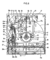
- the cam follower pin 25 is moved from a region of the first cam portion 43a to a region of a second cam portion 53a by movement of the shift bar 17 moved to be pushed by the outer periphery edge C2 of the large diameter disk 14b.
- the first end 50a is maximally displaced toward the outside at a slide top Cmax with the outer periphery edge C2 corresponding to a diameter portion orthogonal to a direction in which the large diameter disk 14b advances. Then, this first end turns in a direction in which the first end returns to its initial position.
- a guide groove for moving the cam follower pin 25 from the inscribed cam front edge 26 to the second cam portion 53a is not particularly provided.
- the second end 50b of the selection arm turns in a direction spaced from the first link portion 44a of the startup arm 20.
- the cam follower pin 25 abuts against the second cam portion 53a by being subjected to the biasing force of the tensile coil spring 24 provided in a tensile manner between the pin and the clamp arm 12. Then, the second link portion 44b of the startup arm 20 is opposed to the end 37a at the rear of the slide rack.
- the startup arm 20 turns around the swivel shaft 22 together with the shift bar 17 moving in the upward direction in the figure (in the direction indicated by the arrow F).
- the cam follower pin 25 moves to the second engagingly locked position 53b along the second cam portion 53a while the pin is subjected to the biasing force of the tensile coil spring 24.
- the cam follower pin 25 reaches the second engagingly locked position 53b, the cam follower pin 25 is retracted into the pocket 53c and is locked there by the biasing force of the tensile coil spring 24 acting on the startup arm 20 whose turning is inhibited. Therefore, in the shift bar 17 subjected to restriction of the startup arm 20, its position is determined, and movement of the large diameter disk 14b is inhibited. Then, the center of the large diameter disk 14b is positioned at the same position as that of the small diameter disk 14a.
- the large diameter disk 14b subjected to action of a tapered boss face at the center of the turntable 16 is moved to its aligned position, whereby the outer periphery edge C2 of the large diameter disk 14b is spaced from the erected piece 17a, and is released from its abutment state in the foregoing pushing and moving operation.
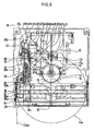
- the small diameter disk 14a stable rotation can be obtained with no contact (refer to FIG. 6).
- the second link portion 44b is abutted against the slide rack end 37a instead of the first link portion 44a. Then, the slide rack 37 is moved to be pushed against the biasing force of the tensile coil spring 38 up to the position at which the tooth portion 37b is geared with the drive pinion 39. Further, an operation for the cam follower 48 to move a relative position to the slide plate 35 braked in abutment against the bent site 47b of the cam groove is carried out in the completely same way as the case of the small diameter disk 14a.
- a startup arm is constrained at a position determined at two points of a swivel shaft and a cam follower pin, and the position of a shift bar is restricted.
- the centers of the disks are aligned with each other at the same position, whereby reliable positioning can be ensured.
- the startup arm is restricted by an inscribed cam fixed at a relative position to a turntable.
- a vibration isolating member is externally provided for a car or for incorporation into a personal computer or the like even in a small space.
- the disk can be easily housed in a floating state. Accordingly, an operation for feeding disks having their different diameters can be carried out reliably with a mechanical construction without using an expensive member such as an optical sensor or a solenoid for detecting and setting the position. Thus, the manufacturing cost can be remarkably reduced.
Landscapes
- Feeding And Guiding Record Carriers (AREA)
Abstract
Description
Claims (4)
- A disk player including a carriage mechanism for basically feeding a selected one of the small diameter or large diameter disks to a turntable and a clamping mechanism for compressing the disk to the turntable, the disk player comprising:a selection arm which abuts against the disk and which can be turned according to its disk diameter;a shift bar which abuts against the disk and which can be moved in a disk feeding direction;a startup arm which is engaged with the shift bar and which turns the shift bar to be interlocked so as to be movable in the disk feeding direction;inscribed cam means in which the startup arm is coupled with a clamp arm of the clamp mechanism via a cam, thereby restricting turning, the cam means being capable of engagingly locking the startup arm at a different position depending on the scale of the diameter of the disk to be fed;first biasing means for biasing the shift bar in a direction opposite to the disk feeding direction; andsecond biasing means for biasing the startup arm, thereby holding the arm at a different engagingly locked position of the inscribed cam, characterized in thatthe disk moving the shift bar to be pushed against a biasing force of the first biasing means turns the selection arm, thereby controlling the startup arm, and the shift bar is restricted by the startup arm held at either of the engagingly locked positions of the inscribed cam, thereby positioning the centers of disks having their different diameters at the same position.
- A disk player as claimed in claim 1, characterized in that the first biasing means and the second biasing means are constructed by providing one tensile coil spring in a tensile manner between the startup arm and the clamp arm.
- A disk player as claimed in claim 1 or claim 2, characterized in that, in the startup arm, a swivel shaft is slidably guided to the clamp arm in a straight groove provided at a right angle relevant to an advancement direction of the disk, and in that a cam follower pin erected at a position spaced from a swivel shaft of the startup arm introduces swiveling of the startup arm while maintaining a slide contact with either of first and second cam portions provided at the inscribed cam corresponding to a respective one of the large and the small diameters of the disks to be fed by a biasing force of the tensile coil spring, the cam follower pin being constrained by either of a first pocket and a second pocket provided at terminals of the first and the second cams, whereby movement of the startup bar is inhibited in cooperation with the swivel shaft restricted in the straight groove.
- A disk player as claimed in claim 1, characterized in that movement from the first cam portion of the cam follower pin to a second cam portion is carried out in planar movement following a path defined by longitudinal movement of the shift bar moving in a disk feeding direction and transverse movement of the startup arm together with swinging movement of the selection arm in a cooperative manner.
Applications Claiming Priority (5)
| Application Number | Priority Date | Filing Date | Title |
|---|---|---|---|
| JP2000293018 | 2000-09-26 | ||
| JP2000293018 | 2000-09-26 | ||
| JP2001070686 | 2001-03-13 | ||
| JP2001070686A JP4621372B2 (en) | 2000-09-26 | 2001-03-13 | Disc player |
| PCT/JP2001/008333 WO2002027719A1 (en) | 2000-09-26 | 2001-09-26 | Disk player |
Publications (3)
| Publication Number | Publication Date |
|---|---|
| EP1324330A1 true EP1324330A1 (en) | 2003-07-02 |
| EP1324330A4 EP1324330A4 (en) | 2006-04-19 |
| EP1324330B1 EP1324330B1 (en) | 2009-01-21 |
Family
ID=26600772
Family Applications (1)
| Application Number | Title | Priority Date | Filing Date |
|---|---|---|---|
| EP01972478A Expired - Lifetime EP1324330B1 (en) | 2000-09-26 | 2001-09-26 | Disk player |
Country Status (5)
| Country | Link |
|---|---|
| US (1) | US6826765B2 (en) |
| EP (1) | EP1324330B1 (en) |
| JP (1) | JP4621372B2 (en) |
| DE (1) | DE60137518D1 (en) |
| WO (1) | WO2002027719A1 (en) |
Families Citing this family (9)
| Publication number | Priority date | Publication date | Assignee | Title |
|---|---|---|---|---|
| JP4621372B2 (en) * | 2000-09-26 | 2011-01-26 | クラリオン株式会社 | Disc player |
| JP4096817B2 (en) * | 2003-06-06 | 2008-06-04 | 日本ビクター株式会社 | Disk drive device |
| JP4155191B2 (en) * | 2003-12-25 | 2008-09-24 | ティアック株式会社 | Disk unit |
| USD558751S1 (en) * | 2004-01-20 | 2008-01-01 | Valley Wood Limited | Disk loading device for player |
| JP4470861B2 (en) * | 2005-11-09 | 2010-06-02 | ソニー株式会社 | Disk transport mechanism and disk drive device |
| JP2008165890A (en) * | 2006-12-27 | 2008-07-17 | Toshiba Corp | Optical disk device |
| DE112008003593B4 (en) | 2008-01-17 | 2014-01-16 | Mitsubishi Electric Corp. | Disc reproducing device |
| TW201013641A (en) * | 2008-09-23 | 2010-04-01 | Quanta Storage Inc | Slot-in type optical disk drive |
| JP2010176758A (en) * | 2009-01-30 | 2010-08-12 | Kenwood Corp | Disk-loading mechanism for disk device |
Family Cites Families (7)
| Publication number | Priority date | Publication date | Assignee | Title |
|---|---|---|---|---|
| JPS59142935U (en) * | 1983-03-11 | 1984-09-25 | パイオニア株式会社 | Autoloading disk player |
| JPH0624033Y2 (en) * | 1988-09-05 | 1994-06-22 | パイオニア株式会社 | Front loading disc player |
| JP2955116B2 (en) | 1992-03-31 | 1999-10-04 | クラリオン株式会社 | Disc loading device |
| JPH1186401A (en) * | 1997-09-04 | 1999-03-30 | Tanashin Denki Co | Disk loading device for disk reproducing device |
| JP4108799B2 (en) * | 1997-11-10 | 2008-06-25 | クラリオン株式会社 | Disc player |
| WO2000079529A1 (en) * | 1999-06-22 | 2000-12-28 | Mitsubishi Denki Kabushiki Kaisha | Disk device |
| JP4621372B2 (en) * | 2000-09-26 | 2011-01-26 | クラリオン株式会社 | Disc player |
-
2001
- 2001-03-13 JP JP2001070686A patent/JP4621372B2/en not_active Expired - Fee Related
- 2001-09-26 EP EP01972478A patent/EP1324330B1/en not_active Expired - Lifetime
- 2001-09-26 US US10/381,688 patent/US6826765B2/en not_active Expired - Lifetime
- 2001-09-26 DE DE60137518T patent/DE60137518D1/en not_active Expired - Lifetime
- 2001-09-26 WO PCT/JP2001/008333 patent/WO2002027719A1/en not_active Ceased
Also Published As
| Publication number | Publication date |
|---|---|
| US20040022160A1 (en) | 2004-02-05 |
| WO2002027719A1 (en) | 2002-04-04 |
| JP2002175658A (en) | 2002-06-21 |
| DE60137518D1 (en) | 2009-03-12 |
| US6826765B2 (en) | 2004-11-30 |
| JP4621372B2 (en) | 2011-01-26 |
| EP1324330B1 (en) | 2009-01-21 |
| EP1324330A4 (en) | 2006-04-19 |
Similar Documents
| Publication | Publication Date | Title |
|---|---|---|
| EP1324330B1 (en) | Disk player | |
| KR0135976B1 (en) | Disc drive | |
| US5012364A (en) | Tape-loading mechanism for a magnetic recording/reproducing apparatus for selective use of tape cassettes of two different sizes | |
| KR940001092B1 (en) | Magnetic recoder reproducing device | |
| CN1169138C (en) | Recording and/or reproducing device having a belt puller and its locking mechanism | |
| US5060096A (en) | Magnetic disc clamping/seating unit | |
| JPH07272417A (en) | Disc player | |
| US7634781B2 (en) | Recording medium driving device | |
| EP1087391B1 (en) | Disc unit | |
| KR100584983B1 (en) | Slot-in type optical disc player | |
| US5327309A (en) | Disk drive apparatus with shutter locking mechanism which is preventive of play of disk cartridge in loading condition | |
| JP4312147B2 (en) | Disc loading device | |
| US20040218481A1 (en) | Slot-in type reproducing/recording apparatus | |
| JP3722506B2 (en) | Cartridge misinsertion prevention device | |
| US6556530B2 (en) | Compatible disk device | |
| JP4147680B2 (en) | Recording / playback device | |
| JP3610658B2 (en) | Disk unit | |
| US7020883B2 (en) | Loading mechanism of disk player | |
| US20090300665A1 (en) | Disc device | |
| US7469412B2 (en) | Disk misinsertion prevention mechanism and disk apparatus including disk misinsertion prevention mechanism | |
| US7984459B2 (en) | Recording medium driving device having an improved disc feeding mechanism | |
| JP4147681B2 (en) | Recording / playback device | |
| JP3638649B2 (en) | Disc player device | |
| JPH09312053A (en) | Magazine insertion detector | |
| JPH0634285B2 (en) | Loading-clamp mechanism |
Legal Events
| Date | Code | Title | Description |
|---|---|---|---|
| PUAI | Public reference made under article 153(3) epc to a published international application that has entered the european phase |
Free format text: ORIGINAL CODE: 0009012 |
|
| 17P | Request for examination filed |
Effective date: 20030325 |
|
| AK | Designated contracting states |
Designated state(s): AT BE CH CY DE DK ES FI FR GB GR IE IT LI LU MC NL PT SE TR |
|
| AX | Request for extension of the european patent |
Extension state: AL LT LV MK RO SI |
|
| RAP1 | Party data changed (applicant data changed or rights of an application transferred) |
Owner name: CLARION CO., LTD. |
|
| RBV | Designated contracting states (corrected) |
Designated state(s): AT BE CH DE FR GB LI |
|
| A4 | Supplementary search report drawn up and despatched |
Effective date: 20060306 |
|
| 17Q | First examination report despatched |
Effective date: 20060927 |
|
| GRAP | Despatch of communication of intention to grant a patent |
Free format text: ORIGINAL CODE: EPIDOSNIGR1 |
|
| RBV | Designated contracting states (corrected) |
Designated state(s): DE FR GB |
|
| GRAS | Grant fee paid |
Free format text: ORIGINAL CODE: EPIDOSNIGR3 |
|
| GRAA | (expected) grant |
Free format text: ORIGINAL CODE: 0009210 |
|
| AK | Designated contracting states |
Kind code of ref document: B1 Designated state(s): DE FR GB |
|
| REG | Reference to a national code |
Ref country code: GB Ref legal event code: FG4D |
|
| REF | Corresponds to: |
Ref document number: 60137518 Country of ref document: DE Date of ref document: 20090312 Kind code of ref document: P |
|
| PLBE | No opposition filed within time limit |
Free format text: ORIGINAL CODE: 0009261 |
|
| STAA | Information on the status of an ep patent application or granted ep patent |
Free format text: STATUS: NO OPPOSITION FILED WITHIN TIME LIMIT |
|
| 26N | No opposition filed |
Effective date: 20091022 |
|
| REG | Reference to a national code |
Ref country code: FR Ref legal event code: PLFP Year of fee payment: 15 |
|
| PGFP | Annual fee paid to national office [announced via postgrant information from national office to epo] |
Ref country code: DE Payment date: 20150922 Year of fee payment: 15 Ref country code: GB Payment date: 20150923 Year of fee payment: 15 |
|
| PGFP | Annual fee paid to national office [announced via postgrant information from national office to epo] |
Ref country code: FR Payment date: 20150811 Year of fee payment: 15 |
|
| REG | Reference to a national code |
Ref country code: DE Ref legal event code: R119 Ref document number: 60137518 Country of ref document: DE |
|
| GBPC | Gb: european patent ceased through non-payment of renewal fee |
Effective date: 20160926 |
|
| REG | Reference to a national code |
Ref country code: FR Ref legal event code: ST Effective date: 20170531 |
|
| PG25 | Lapsed in a contracting state [announced via postgrant information from national office to epo] |
Ref country code: FR Free format text: LAPSE BECAUSE OF NON-PAYMENT OF DUE FEES Effective date: 20160930 Ref country code: DE Free format text: LAPSE BECAUSE OF NON-PAYMENT OF DUE FEES Effective date: 20170401 Ref country code: GB Free format text: LAPSE BECAUSE OF NON-PAYMENT OF DUE FEES Effective date: 20160926 |