EP1324271A2 - Row-wise full helical view weighting method and apparatus for CT scanners - Google Patents

Row-wise full helical view weighting method and apparatus for CT scanners Download PDF

Info

Publication number
EP1324271A2
EP1324271A2 EP02257741A EP02257741A EP1324271A2 EP 1324271 A2 EP1324271 A2 EP 1324271A2 EP 02257741 A EP02257741 A EP 02257741A EP 02257741 A EP02257741 A EP 02257741A EP 1324271 A2 EP1324271 A2 EP 1324271A2
Authority
EP
European Patent Office
Prior art keywords
row
helical
weighted
detector
array
Prior art date
Legal status (The legal status is an assumption and is not a legal conclusion. Google has not performed a legal analysis and makes no representation as to the accuracy of the status listed.)
Withdrawn
Application number
EP02257741A
Other languages
German (de)
French (fr)
Other versions
EP1324271A3 (en
Inventor
Sharon Wang
Stephen Metz
Thomas Toth
Piero U. Simoni
Jianying Li
Current Assignee (The listed assignees may be inaccurate. Google has not performed a legal analysis and makes no representation or warranty as to the accuracy of the list.)
GE Medical Systems Global Technology Co LLC
Original Assignee
GE Medical Systems Global Technology Co LLC
Priority date (The priority date is an assumption and is not a legal conclusion. Google has not performed a legal analysis and makes no representation as to the accuracy of the date listed.)
Filing date
Publication date
Application filed by GE Medical Systems Global Technology Co LLC filed Critical GE Medical Systems Global Technology Co LLC
Publication of EP1324271A2 publication Critical patent/EP1324271A2/en
Publication of EP1324271A3 publication Critical patent/EP1324271A3/en
Withdrawn legal-status Critical Current

Links

Images

Classifications

    • GPHYSICS
    • G06COMPUTING OR CALCULATING; COUNTING
    • G06TIMAGE DATA PROCESSING OR GENERATION, IN GENERAL
    • G06T12/00Tomographic reconstruction from projections
    • G06T12/10Image preprocessing, e.g. calibration, positioning of sources or scatter correction
    • AHUMAN NECESSITIES
    • A61MEDICAL OR VETERINARY SCIENCE; HYGIENE
    • A61BDIAGNOSIS; SURGERY; IDENTIFICATION
    • A61B6/00Apparatus or devices for radiation diagnosis; Apparatus or devices for radiation diagnosis combined with radiation therapy equipment
    • A61B6/02Arrangements for diagnosis sequentially in different planes; Stereoscopic radiation diagnosis
    • A61B6/027Arrangements for diagnosis sequentially in different planes; Stereoscopic radiation diagnosis characterised by the use of a particular data acquisition trajectory, e.g. helical or spiral
    • AHUMAN NECESSITIES
    • A61MEDICAL OR VETERINARY SCIENCE; HYGIENE
    • A61BDIAGNOSIS; SURGERY; IDENTIFICATION
    • A61B6/00Apparatus or devices for radiation diagnosis; Apparatus or devices for radiation diagnosis combined with radiation therapy equipment
    • A61B6/02Arrangements for diagnosis sequentially in different planes; Stereoscopic radiation diagnosis
    • A61B6/03Computed tomography [CT]
    • A61B6/032Transmission computed tomography [CT]
    • GPHYSICS
    • G01MEASURING; TESTING
    • G01TMEASUREMENT OF NUCLEAR OR X-RADIATION
    • G01T1/00Measuring X-radiation, gamma radiation, corpuscular radiation, or cosmic radiation
    • G01T1/29Measurement performed on radiation beams, e.g. position or section of the beam; Measurement of spatial distribution of radiation
    • G01T1/2914Measurement of spatial distribution of radiation
    • G01T1/2985In depth localisation, e.g. using positron emitters; Tomographic imaging (longitudinal and transverse section imaging; apparatus for radiation diagnosis sequentially in different planes, steroscopic radiation diagnosis)
    • YGENERAL TAGGING OF NEW TECHNOLOGICAL DEVELOPMENTS; GENERAL TAGGING OF CROSS-SECTIONAL TECHNOLOGIES SPANNING OVER SEVERAL SECTIONS OF THE IPC; TECHNICAL SUBJECTS COVERED BY FORMER USPC CROSS-REFERENCE ART COLLECTIONS [XRACs] AND DIGESTS
    • Y10TECHNICAL SUBJECTS COVERED BY FORMER USPC
    • Y10STECHNICAL SUBJECTS COVERED BY FORMER USPC CROSS-REFERENCE ART COLLECTIONS [XRACs] AND DIGESTS
    • Y10S378/00X-ray or gamma ray systems or devices
    • Y10S378/901Computer tomography program or processor

Definitions

  • the present invention relates to multi-slice helical computerized tomography and more particularly to a tomography algorithm, method and apparatus which reduces the data acquisition time and data processing time required to generate an image while maintaining high image quality.
  • CT computerized tomography
  • X-ray photon rays are directed through a patient toward a detector.
  • Attenuated rays are detected by the detector, the amount of attenuation indicative of the make up (e.g. bone, flesh, air pocket, etc.) of the patient through which the rays traversed.
  • the attenuation data is then processed and back-projected according to a reconstruction algorithm to generate an image of the patient's internal anatomy.
  • back-projection is performed in software but, as the name implies, is akin to physically projecting rays from many different angles within an image plane through the image plane, the values of rays passing through the same image voxels being combined in some manner to have a combined effect on the voxel in the resulting image.
  • back-projection rays the data corresponding to rays which are back-projected will be referred to as back-projection rays.
  • fan beam acquisition the source is collimated into a thin fan beam which is directed at a detector on a side opposite a patient.
  • a complete fan beam projection data set is instantaneously generated for a beam angle defined by a central ray of the source fan beam.
  • the source and detector are rotated about an image plane to collect data from all (e.g., typically 360 degrees) beam angles. Thereafter the collected data is used to reconstruct an image in the image plane.
  • fan beam acquisition reduces acquisition period duration.
  • conjugate data acquisitions i.e., data acquired along the same path from opposite directions
  • at least one ray can be directed through an image plane from every possible beam angle without having to perform a complete rotation about the patient.
  • data corresponding to every beam angle associated with a single image plane can be collected after a ( ⁇ + 2 ⁇ )/2 ⁇ rotation about the patient where ⁇ is the fan beam angle.
  • these acquisition methods and systems are generally referred to as half-scan methods and systems.
  • half-scan acquisition has been employed to reduce acquisition period duration in conjunction with single row detectors.
  • Single slice detectors, fan beams and half-scans can be used to generate data in several different parallel image planes which, after data acquisition, can be used by a processor to generate an image anywhere between the image planes through interpolation/extrapolation procedures known in the art. For example, assume that during two data acquisition periods first and second data sets were acquired which correspond to first and second parallel acquisition planes, respectively, the planes separated by 0.25 inches. If a user selects an image plane for reconstructing an image which resides between the first and second acquisition planes, interpolation between data in the first and second sets can be used to estimate values of data corresponding to the selected image plane.
  • multi-row detector with a fan beam.
  • a relatively thick fan beam is collimated and directed through a patient at a multi-row detector, each detector row in effect gathering data for a separate "slice" of the thick fan beam along the Z or translation axis perpendicular to a fan beam width.
  • the detected signals in each row correspond to a plane centered within the row as projected onto the isocenter Z.
  • the central plane through a row will be referred to as a row center.
  • an interface After data acquisition an interface enables a system user to select an image plane from within the area corresponding to the collected data.
  • the selected image plane is between the row centers of at least two adjacent detector rows.
  • a processor interpolates between data corresponding to adjacent rows to generate back-projection rays corresponding to the selected image plane.
  • the processor again identifies an acquired data subset for interpolation, additional processing and back-projection.
  • One limitation with multi-row detectors is that, during a single acquisition period, data can only be collected which corresponds to the detector thickness.
  • data can only be collected which corresponds to the detector thickness.
  • ROI region of interest
  • the patient has to be moved along a translation axis until a second volume which is adjacent the first volume is between the source and detector. Thereafter a second acquisition process has to be performed.
  • FOI region of interest
  • the patient has to be transported to another relative location with respect to the source and detector.
  • Required translation without acquisition necessarily prolong the acquisition period and the additional acquisition time and aligning processes inevitably result in relative discomfort, additional patient movements and undesirable image artifacts.
  • Helical scanning systems have been developed so that data can be collected during a single acquisition period without halting patient translation during the acquisition period.
  • the source and detector array are mounted on opposing surfaces of an annular gantry and are rotated there around as a patient is transported at constant speed through the gantry.
  • the X-ray beam sweeps a helical path through the patient, hence the nomenclature "helical scanning system”.
  • Data acquisition can be sped up by increasing operating pitch (i.e., table translation speed relative to gantry rotation rate).
  • After data is acquired the data is processed to generate back-projection ray estimates and account for data nuances which are caused by the helical acquisition.
  • the collected data includes “views” where each view includes the data corresponding to the entire detector that is collected from a specific source angle about the gantry.
  • view will be used to identify the data corresponding to a specific detector row acquired at a specific gantry angle so that a four row detector will have first, second, third and fourth separate row views at each gantry angle.
  • a system processor selects a sub-set of the helical data (hereinafter "a selected data subset") which is, in effect, centered on the selected plane. Thereafter, the selected data sub-set is altered to generate slice image data corresponding to the slice image plane, the altered data is filtered and back-projected across the slice image plane to generate the desired image for viewing and further processing.
  • the back-projected data must include views from many equispaced gantry angles about the slice plane.
  • the selected data sub-set including data from all four detector rows is weighted according to an algorithm that is spatially dependent along the Z or translation axis.
  • an algorithm that is spatially dependent along the Z or translation axis.
  • at least one row view will typically be aligned with the slice image plane and therefore can be used for imaging purposes in its acquired state (i.e., without weighting).
  • the gantry angle corresponding to an aligned row view will be referred to as an aligned angle.
  • the selected data set will include two row views preceding the image plane and two row views following the image plane.
  • the selected data set will include either one row view preceding the image plane and three row views following the image plane or vice versa.
  • the proximate row views are weighted generally as a function of spacing along the Z-axis. For instance, for a given gantry angle where the slice image plane is between second and third detector row views and is closer to the second row view than the third row view, the row view weightings from highest to lowest are second, third, first and fourth, respectively. After each row view within the selected data sub-set is weighted, the weighted data is filtered and back-projected to generate the required image. In this manner, a full set of weighted views is created to perform a conventional 360° CT reconstruction.
  • the present invention includes a new weighting algorithm and method that can be used with detectors having virtually any number of detector element rows to generate highly accurate images from helically scanned CT data.
  • the inventive algorithm generally includes two sequential weighting processes. First, after helically scanned data has been collected for a region of interest (ROI) and a transaxial slice image plane through the ROI has been identified, a sub-set of data corresponding to the selected slice image plane is identified and then a helical weighting algorithm is applied separately to the data corresponding to each of the detector rows to generate a separate helical weighted array for each detector row. For instance, where a detector includes eight detector rows, eight separate helical weighted arrays are generated.
  • ROI region of interest
  • the inventive weighting function applied to each row view is both gantry angle ⁇ and beam angle ⁇ dependent.
  • the weighting function has a value of one
  • the weighting function has a value of zero and between lines 131 and 130 and lines 132 and 130 the weighting function slopes from zero to one.
  • the slope of lines 130, 131 and 130 is referred to generally as a tangent weighting parameter t g which, after system pitch and detector width are set, can be modified through an optimization process until optimal imaging characteristics result (e.g., artifacts and noise are minimized).
  • a conjugate weighting function is applied to each helical weighted array thereby generating a separate conjugate weighted array for each detector row.
  • conjugate weighting After conjugate weighting is applied the resulting conjugate weighted arrays are filtered and back-projected thereby generating a slice image corresponding to the selected slice image plane.
  • the conjugate weighted arrays may be combined before filtering and back-projection or the filtering and back-projection may be performed on a row by row basis to generate row specific slice images which are then combined to generate a final or combined slice image.
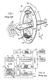
  • a CT scanner for use with the present invention includes a gantry 20 having an opening (i.e., defining an imaging area) supporting an x-ray source 10 oriented to project a fan beam 40 of x-rays along the beam axis 41 through a patient 42 to a supported and opposed detector array 44.
  • the gantry 20 rotates to swing the beam axis within a gantry plane 38 defining the x-y plane of a Cartesian coordinate system. Rotation of the gantry 20 is measured by beam angle ⁇ from an arbitrary reference position within the gantry plane 38.
  • a patient 42 resets on a table 46 which may be moved along a translation axis 48 aligned with the Z-axis of the Cartesian coordinate system.
  • Table 46 crosses gantry plane 38 and is radio- translucent so as not to interfere with the imaging process.
  • the x-rays of the fan beam 40 diverge from the beam axis 41 within the gantry plane 38 across a transverse axis 50 generally orthogonal to both the beam axis 41 and the translation axis 48 at a fan beam angle ⁇ .
  • the x-rays of beam 40 also diverge slightly from the beam axis 41 and the gantry plane 38 across the Z-axis 48.
  • a maximum beam angle ⁇ is identified hereinafter by symbol ⁇ .
  • detector array 44 After passing through patient 42, the x-rays of the fan beam 40 are received by detector array 44 which includes a plurality of detector elements 18'.
  • detector elements 18' in exemplary array 44 are arranged in eight rows R1 through R8 (i.e., array 44 is an eight slice detector) extending along the traverse axis 50 that subdivide array 44 along the Z-axis and a plurality of columns extending along Z-axis 48.
  • the width W of detector array 44 is measured along Z-axis 48.
  • the surface of detector array 44 may be planar or may follow a section of a sphere or cylinder having a center at focal spot 26 or alternatively at the system isocenter.
  • the detector elements 18' each receive x-rays and provide intensity measurements along separate rays of the fan beam 40.
  • Each intensity measurement describes the attenuation via a line integral of one fan beam ray passing through a portion of volume 43 of patient 42.
  • the dimension of volume 43 along Z-axis 48 is greater than the Z-axis width of eight slice array 44.
  • an exemplary control system for controlling the CT imaging system of Fig. 1 includes gantry associated control modules collectively identified by numeral 52, a table motor control 58, slip rings 64, a central processing computer 60, an operator's console 65 and a mass storage device 66.
  • Modules 52 include an x-ray control 54, a gantry motor control 56, a data acquisition system 62 and an image reconstructor 68.
  • X-ray control 54 provides power and timing signals to the x-ray source 10 to turn it on and off as required under the control of a computer 60.
  • Gantry motor control 56 controls the rotational speed and position of the gantry 20 and provides information to computer 60 regarding gantry position.
  • Data acquisition system 62 samples and digitizes intensity signals from the detector elements 18' of detector array 44 provides the digitized signals in the form of helical data row views to computer 60 for storage in mass storage device 66.
  • Reconstructor 68 is linked to computer 60 for receiving data there from and weighting the data according to the inventive method, filtering the weighted data and back-projecting the data to, as its label implies, construct a slice image for viewing.
  • Each of the above modules is connected to associated gantry mounted components via slip rings 64 and is also linked to computer 60 for control purposes
  • Slip rings 64 permit gantry 20 to rotate continuously through angles greater than 360° to acquire projection data.
  • the speed and position of table 46 along translation axis 48 is controlled by computer 60 by means of table motor control 58.
  • Computer 60 receives commands and scanning parameters via operator console 65 that generally includes some type of visual interface device (e.g., a CRT display) and one or more input devices (e.g., a keyboard, a mouse controlled display cursor, etc.).
  • Console 65 allows an operator to enter parameters for controlling a data acquiring scan and to display constructed image and other information from computer 60.
  • Mass storage device or memory 66 provides a means for storing operating programs for the CT imaging system, as well as image data for future reference by the operator. Both computer 60 and the image reconstructor 68 have associated electronic memory (not shown) for storing data and pulse sequencing programs.
  • gantry motor control 56 brings gantry 20 up to a rotational speed and table motor control 58 begins translation of table 46 along translation axis 48.
  • the x-ray control 54 turns on x-ray source 10 and projection data is acquired on a continuous basis.
  • the table 46 translation speed relative to the gantry rotation rate is referred to as the operating "pitch".
  • the projection data acquired comprises intensity signals corresponding to each detector element 18' at each particular column and row of array 44.
  • the collected data is stored in storage device 66 as helical data including row views correlated to gantry angles.
  • the eight rows R1-R8 of detectors 44 define in an eight fan beam system.
  • the x-ray fan beam 40 is, in effect, split into eight fan beams displaced along the Z-axis.
  • image reconstructor 68 includes a summer 118 a filter and back-projector 116 and separate processing circuitry assemblies for each of the detector rows R1 through R8, the separate assemblies identified by labels 100(R1) through 100(R8), respectively.
  • Each of assemblies 100(R1) through 100(R8) is essentially identical and operates in a similar fashion and therefore, in the interest of simplifying this explanation, only circuitry assembly 100(R1) is explained here in detail.
  • assembly 100(R1) processes data row views generated by row R1 of detector array 44
  • assembly 100(R2) processes data row views generated by row R2 of array 44
  • array output signals of assemblies 100(R1) through 100(R8) are provided to summer 118 which adds the array signals to generate weighting data views within a selected slice image plane that can be filtered and back-projected to generate an image corresponding to the image plane.
  • assembly 100(R1) includes a preprocessor 102, first and second multipliers 112 and 115, respectively, a helical weighting function module 106 and a conjugate weighting function module 110.
  • Assembly 100(R1) components receive row views corresponding to detector row R1 and alter the received views several times to generate intermediate data arrays, the end result being a conjugate weighted array 114 corresponding to row R1.
  • the arrays are identified by blocks having rounded edges while assembly components are identified by blocks having sharp angles.
  • the intermediate arrays include a projection data array 104 and a helical weighted array 108.
  • each row view of data from DAS 62 for corresponding to detector row R1 is provided to preprocessor 102 where the view data is preprocessed to correct for various well-known errors such as beam hardening, offsets and variations in detector and channel gain.
  • preprocessor 102 generates the negative logarithm of the view to provide projection data which is stored as the projection data array 104.
  • the projection data array 104 is read out and the helical weighting function generated by module 106 is applied to the projection data array 104 by multiplier 112 thereby generating the helical weighted array 108 which is again stored.
  • the helical weighted array 108 is read out and the conjugate weighting function generated by module 110 is applied to the helical weighted array 108 by multiplier 115 thereby generating the conjugate weighted array 114 which is once again stored.
  • the conjugate weighted array 114 is provided to summer 118 along with similar arrays from assemblies 100(R2) through 100(R8).
  • the arrays are summed by summer 118 to generate a combined slice plane data array.
  • the combined array is provided to filter-back-projector 116 which filters and back-projects the combined array views to produce the slice image 120.
  • the resulting slice image array 120 is stored in device 66 for later use or may be displayed to the operator via console 65.
  • each conjugate weighted array may be separately filtered and back-projected to generate separate image data arrays for each row. Thereafter, the separate image data arrays may be summed on a pixel-by-pixel basis to generate the combined and final slice image array 120.
  • an inventive method generally includes two separate sub-processes including a helical weighting process and a conjugate weighting process. These two processes will be described sequentially.
  • label d denotes the detector row spacing measured (i.e., the z-axis spacing) at the axis of gantry rotation 48
  • s denotes the table feeding speed per gantry rotation
  • gantry angle ⁇ 1 corresponds to a selected slice image plane within which an image is to be generated.
  • Lines 130, 131 and 132 correspond to one, zero and zero weighting values, respectively, with the region between lines 131 and 130 ramping from zero to one and the region between lines 132 and 130 similarly ramping from zero to one.
  • the weight values vary as a function of both the gantry angle ⁇ and the fan angle ⁇ within specific row views (i.e., within a view corresponding to a specific gantry angle ⁇ ).
  • a central ray ⁇ 1 has a weight value of one while other rays within the row view have weights between one and zero (i.e., between lines 130 and either 131 or 132 as illustrated).
  • Pitch p and detector width are typically selected.
  • Line 130 slope clearly affects the weighting function and therefore is extremely important and is set during an optimization commissioning process wherein a tangent weighting parameter t g is adjusted to alter the slope until optimal imaging characteristics result (e.g., noise and artifacts are minimized).
  • is a gantry angle centered on the selected imaging plane and central within the data corresponding to a specific row, and r is the detector row which ranges from zero to N-1 where N is the number of rows in a detector 44.
  • the summed weights for the gantry and phase angles within regions 146 and 148 is zero while the summed weights for the gantry and phase angles within regions 142 and 144 ramp from zero to one between regions 146 and 148 and region 140, respectively.
  • the illustrated summed weighting function is unique.
  • a conjugate weighting function has been developed that can be expressed by the following equations: where w 0 and w n are helical weighting functions for the first and last detector rows (e.g., R1 and R8 in Fig. 3), and ⁇ n 0 and ⁇ n c are the conjugate parameters (i.e., gantry angles) corresponding to the beginning of the first row and the end of the last row, respectively.
  • FIGs. 8 and 9 three and two dimensional graphs similar to those of Figs. 6 and 7 are provided, respectively, that show the final weights after combining the conjugate weights and the helical weights.
  • Figs. 8 and 9 there are nine separately weighted regions including a region 150 having a weight of two, region 154 having combined weights of one, region 164 having combined weights of one, region 156 having combined weights of zero, region 158 having combined weights of zero, region 162 ramps from zero to one between regions 156 and 164, region 168 ramps from zero to one between regions 158 and 154, region 152 ramps from one to two between regions 164 and 150 and region 160 ramps from one to two between regions 154 and 150.
  • the weighting function of Figs. 8 and 9 is unique.
  • a thicker slice can be derived by summing multiple thin slices within the desired slice profile. If the multiple thin slices by themselves are not of interest, the intermediate step of reconstructing multiple thin slices can be bypassed by performing the corresponding summation early in the projection domain. This reduces the computation load and the image storage load.
  • the resultant weighting functions can be derived by summing corresponding shifted versions of the data planes.
  • CT system described herein is a “third generation” system in which both the x-ray source and detector rotate with the gantry.
  • CT systems including "fourth generation” systems wherein the detector is a full-ring stationary detector and only the x-ray source rotates with the gantry, may be used.

Landscapes

  • Health & Medical Sciences (AREA)
  • Life Sciences & Earth Sciences (AREA)
  • Engineering & Computer Science (AREA)
  • Physics & Mathematics (AREA)
  • Medical Informatics (AREA)
  • High Energy & Nuclear Physics (AREA)
  • Molecular Biology (AREA)
  • Pathology (AREA)
  • General Physics & Mathematics (AREA)
  • Veterinary Medicine (AREA)
  • Nuclear Medicine, Radiotherapy & Molecular Imaging (AREA)
  • Optics & Photonics (AREA)
  • Theoretical Computer Science (AREA)
  • Radiology & Medical Imaging (AREA)
  • Biomedical Technology (AREA)
  • Heart & Thoracic Surgery (AREA)
  • Biophysics (AREA)
  • Surgery (AREA)
  • Animal Behavior & Ethology (AREA)
  • General Health & Medical Sciences (AREA)
  • Public Health (AREA)
  • Pulmonology (AREA)
  • Spectroscopy & Molecular Physics (AREA)
  • Apparatus For Radiation Diagnosis (AREA)
  • Image Processing (AREA)
  • Image Analysis (AREA)

Abstract

A method and apparatus for performing image reconstruction using data obtained by an N beam helical scan, the method including generating (102) projection data arrays (104) for each of the N row (R1-R8) in a CT detector, weighting (112) the data arrays using a unique weighting function (106) that is applicable to detectors having many different numbers of rows N to generate helical weighted arrays (108) for each row, weighting (115) the helical weighted arrays (108) by applying a conjugate weighting function (110) to generate conjugate arrays (114) for each detector row and then combining the conjugate weighted arrays (118), filtering and back-projecting (116) to generate a slice image (102).

Description

The present invention relates to multi-slice helical computerized tomography and more particularly to a tomography algorithm, method and apparatus which reduces the data acquisition time and data processing time required to generate an image while maintaining high image quality.
In computerized tomography (CT) X-ray photon rays are directed through a patient toward a detector. Attenuated rays are detected by the detector, the amount of attenuation indicative of the make up (e.g. bone, flesh, air pocket, etc.) of the patient through which the rays traversed. The attenuation data is then processed and back-projected according to a reconstruction algorithm to generate an image of the patient's internal anatomy. Generally, the "back-projection" is performed in software but, as the name implies, is akin to physically projecting rays from many different angles within an image plane through the image plane, the values of rays passing through the same image voxels being combined in some manner to have a combined effect on the voxel in the resulting image. Hereinafter the data corresponding to rays which are back-projected will be referred to as back-projection rays.
During data acquisition, if a patient moves, artifacts can occur in the resulting image which often render images useless or difficult to use for diagnostics purposes. For this and other reasons the CT industry is constantly trying to identify ways to reduce the duration of acquisition periods without reducing the quality of the data acquired.
Various CT system features and procedures have been developed to increase data acquisition speed. Some of the more popular features and procedures including fan beam acquisition, simultaneous multiple slice acquisition, helical scanning and half-scanning. In fan beam acquisition the source is collimated into a thin fan beam which is directed at a detector on a side opposite a patient. In this manner, a complete fan beam projection data set is instantaneously generated for a beam angle defined by a central ray of the source fan beam. The source and detector are rotated about an image plane to collect data from all (e.g., typically 360 degrees) beam angles. Thereafter the collected data is used to reconstruct an image in the image plane. Thus, fan beam acquisition reduces acquisition period duration.
With respect to half-scanning, assuming a patient remains still during a data acquisition period, conjugate data acquisitions (i.e., data acquired along the same path from opposite directions) should be identical. In addition, using a fan beam, at least one ray can be directed through an image plane from every possible beam angle without having to perform a complete rotation about the patient. To this end, as known in the industry, data corresponding to every beam angle associated with a single image plane can be collected after a (□ + 2□)/2□ rotation about the patient where □ is the fan beam angle. Because less than an entire rotation about a patient is required to acquire data corresponding to a slice image, these acquisition methods and systems are generally referred to as half-scan methods and systems. Thus, half-scan acquisition has been employed to reduce acquisition period duration in conjunction with single row detectors.
Single slice detectors, fan beams and half-scans can be used to generate data in several different parallel image planes which, after data acquisition, can be used by a processor to generate an image anywhere between the image planes through interpolation/extrapolation procedures known in the art. For example, assume that during two data acquisition periods first and second data sets were acquired which correspond to first and second parallel acquisition planes, respectively, the planes separated by 0.25 inches. If a user selects an image plane for reconstructing an image which resides between the first and second acquisition planes, interpolation between data in the first and second sets can be used to estimate values of data corresponding to the selected image plane. For instance, assume that, among other rays, during the acquisition periods a first ray and a second ray were used to generate data in the first and second sets, respectively, and that the first and second rays were parallel (i.e. had the same beam and fan angles). In this case, by interpolating between the data acquired from the first and second rays generates an estimated value corresponding to a hypothetical back-projection ray which is parallel to the first and second rays and which is within the image plane. By performing such interpolation to generate back-projection rays for every beam and fan angle through the image plane a complete data set corresponding to the image plane is generated.
While such systems work, unfortunately, the acquisition time required to generate data corresponding to many image planes is excessive and inevitable patient movement often causes image artifacts.
One way to speed up data acquisition corresponding to several image planes is by employing a multi-row detector with a fan beam. In multi-row detector systems, a relatively thick fan beam is collimated and directed through a patient at a multi-row detector, each detector row in effect gathering data for a separate "slice" of the thick fan beam along the Z or translation axis perpendicular to a fan beam width. Despite each detector row having a thickness, in these systems it is assumed that the detected signals in each row correspond to a plane centered within the row as projected onto the isocenter Z. Hereinafter the central plane through a row will be referred to as a row center.
After data acquisition an interface enables a system user to select an image plane from within the area corresponding to the collected data. The selected image plane is between the row centers of at least two adjacent detector rows. After image plane selection, a processor interpolates between data corresponding to adjacent rows to generate back-projection rays corresponding to the selected image plane. When another image corresponding to a different image plane is desired, after selecting the plane, the processor again identifies an acquired data subset for interpolation, additional processing and back-projection. Thus, multi-row detector systems further reduce data acquisition period duration where several image planes may be selected for reconstruction.
One limitation with multi-row detectors is that, during a single acquisition period, data can only be collected which corresponds to the detector thickness. To collect additional data corresponding to a greater patient volume or region of interest (ROI), after one acquisition period corresponding to a first volume, the patient has to be moved along a translation axis until a second volume which is adjacent the first volume is between the source and detector. Thereafter a second acquisition process has to be performed. Similarly, to collect additional data corresponding to a third volume the patient has to be transported to another relative location with respect to the source and detector. Required translation without acquisition necessarily prolong the acquisition period and the additional acquisition time and aligning processes inevitably result in relative discomfort, additional patient movements and undesirable image artifacts.
Helical scanning systems have been developed so that data can be collected during a single acquisition period without halting patient translation during the acquisition period. In a helical scanning system, the source and detector array are mounted on opposing surfaces of an annular gantry and are rotated there around as a patient is transported at constant speed through the gantry. The X-ray beam sweeps a helical path through the patient, hence the nomenclature "helical scanning system". Data acquisition can be sped up by increasing operating pitch (i.e., table translation speed relative to gantry rotation rate). After data is acquired the data is processed to generate back-projection ray estimates and account for data nuances which are caused by the helical acquisition.
Various combinations of the fan-beam, multi-slice, half-scan and helical scanning features have been combined to realize synergies and have been somewhat successful. For example, one system combines a multi-row fan beam detector and a fan beam source with a helical scanning procedure to rapidly acquire imaging data using a high pitch/high speed mode of operation. For example, US patent No. 5,541,970 (hereinafter "the '970 patent") which issued on July 30, 1996 and is entitled "Image Reconstruction for a CT System Implementing Four Fan Beam Helical Scan" teaches an exemplary system including a four row detector where, during acquisition, helical data is collected about an ROI for each of the four rows. The collected data includes "views" where each view includes the data corresponding to the entire detector that is collected from a specific source angle about the gantry. Hereinafter, the phrase "row view" will be used to identify the data corresponding to a specific detector row acquired at a specific gantry angle so that a four row detector will have first, second, third and fourth separate row views at each gantry angle.
After data has been collected and stored, when a system operator identifies a transaxial plane through the ROI at which a required image is to be generated, a system processor selects a sub-set of the helical data (hereinafter "a selected data subset") which is, in effect, centered on the selected plane. Thereafter, the selected data sub-set is altered to generate slice image data corresponding to the slice image plane, the altered data is filtered and back-projected across the slice image plane to generate the desired image for viewing and further processing. In order to generate a high quality image, the back-projected data must include views from many equispaced gantry angles about the slice plane.
In order to convert the selected data sub-set into slice image data for filtering and back-projection, the selected data sub-set including data from all four detector rows is weighted according to an algorithm that is spatially dependent along the Z or translation axis. To this end, for each detector row, at least one row view will typically be aligned with the slice image plane and therefore can be used for imaging purposes in its acquired state (i.e., without weighting). Hereinafter the gantry angle corresponding to an aligned row view will be referred to as an aligned angle.
For each remaining gantry angle in the slice image plane there are other row views within the selected data sub-set proximate the imaging plane. For instance, in the case of a four row detector, for gantry angles that are similar to the aligned angle, the selected data set will include two row views preceding the image plane and two row views following the image plane. For other gantry angles that are less similar to the aligned angle the selected data set will include either one row view preceding the image plane and three row views following the image plane or vice versa.
In any event, for each remaining gantry angle (i.e., all gantry angles that are not aligned with the slice image plane) in the slice image plane, the proximate row views are weighted generally as a function of spacing along the Z-axis. For instance, for a given gantry angle where the slice image plane is between second and third detector row views and is closer to the second row view than the third row view, the row view weightings from highest to lowest are second, third, first and fourth, respectively. After each row view within the selected data sub-set is weighted, the weighted data is filtered and back-projected to generate the required image. In this manner, a full set of weighted views is created to perform a conventional 360° CT reconstruction.
While the algorithm described in the '970 patent works well for four row detectors, unfortunately, when larger detectors are designed to collect additional rows of data (e.g., eight row detectors), it has been found that a higher helical pitch (i.e., table translation speed relative to gantry rotation rate) and larger cone angles (i.e., the angles between X-ray beams within the Z or translation axis) result which cause image artifacts and appreciably adversely affect the diagnostic value of resulting images.
The present invention includes a new weighting algorithm and method that can be used with detectors having virtually any number of detector element rows to generate highly accurate images from helically scanned CT data. The inventive algorithm generally includes two sequential weighting processes. First, after helically scanned data has been collected for a region of interest (ROI) and a transaxial slice image plane through the ROI has been identified, a sub-set of data corresponding to the selected slice image plane is identified and then a helical weighting algorithm is applied separately to the data corresponding to each of the detector rows to generate a separate helical weighted array for each detector row. For instance, where a detector includes eight detector rows, eight separate helical weighted arrays are generated.
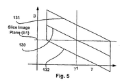
Importantly, referring to Fig. 5 where an exemplary inventive weighting function is illustrated in two dimensions, the inventive weighting function applied to each row view is both gantry angle β and beam angle γ dependent. To this end, along line 130 the weighting function has a value of one, along each of lines 131 and 132 the weighting function has a value of zero and between lines 131 and 130 and lines 132 and 130 the weighting function slopes from zero to one. The slope of lines 130, 131 and 130 is referred to generally as a tangent weighting parameter tg which, after system pitch and detector width are set, can be modified through an optimization process until optimal imaging characteristics result (e.g., artifacts and noise are minimized)..
Second, after the helical weighting function has been applied and helical weighted arrays for each row have been generated, a conjugate weighting function is applied to each helical weighted array thereby generating a separate conjugate weighted array for each detector row.
After conjugate weighting is applied the resulting conjugate weighted arrays are filtered and back-projected thereby generating a slice image corresponding to the selected slice image plane. The conjugate weighted arrays may be combined before filtering and back-projection or the filtering and back-projection may be performed on a row by row basis to generate row specific slice images which are then combined to generate a final or combined slice image.
These and other aspects of the invention will become apparent from the following description. In the description, reference is made to the accompanying drawings which form a part hereof, and in which there is shown a preferred embodiment of the invention. Such embodiment does not necessarily represent the full scope of the invention and reference is made therefore, to the claims herein for interpreting the scope of the invention.
The invention will now be described in greater detail, by way of example, with reference to the drawings, in which:-
  • Fig. 1 is a perspective view of a CT apparatus used to practice the present invention which includes a detector array having rows and columns of detector elements and fan beam source;
  • Fig. 2 is a block diagram of CT control system which may be used to control the CT apparatus of Fig. 1 and which is useful for the purposes of practicing the present invention;
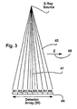
  • Fig. 3 is a schematic diagram illustrating an X-ray source and an eight row detector that divides the source beam into eight separate radiation beams;
  • Fig. 4 is a schematic diagram illustrating an exemplary image reconstructor according to the present invention;
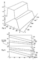
  • Fig. 5 is a graph illustrating an exemplary weighting algorithm in two dimensions that is applied on a detector row by row basis according to the present invention;
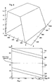
  • Fig. 6 a three dimensional graph illustrating the summation of weights across a plurality of detector rows after the helical weighting function illustrated in Fig. 5 has been applied;
  • Fig. 7 is a two-dimensional graph corresponding to Fig. 6;
  • Fig. 8 is similar to Fig. 6 albeit illustrating a three-dimensional graph corresponding to summed weights after both the helical weighting function and a conjugate weighting function have been applied; and
  • Fig. 9 is a similar to Fig. 7, albeit corresponding to the three-dimensional graph illustrated in Fig. 8.
  • A. Hardware
    Referring now to Fig. 1, a CT scanner for use with the present invention includes a gantry 20 having an opening (i.e., defining an imaging area) supporting an x-ray source 10 oriented to project a fan beam 40 of x-rays along the beam axis 41 through a patient 42 to a supported and opposed detector array 44. The gantry 20 rotates to swing the beam axis within a gantry plane 38 defining the x-y plane of a Cartesian coordinate system. Rotation of the gantry 20 is measured by beam angle □ from an arbitrary reference position within the gantry plane 38.
    A patient 42 resets on a table 46 which may be moved along a translation axis 48 aligned with the Z-axis of the Cartesian coordinate system. Table 46 crosses gantry plane 38 and is radio- translucent so as not to interfere with the imaging process.
    The x-rays of the fan beam 40 diverge from the beam axis 41 within the gantry plane 38 across a transverse axis 50 generally orthogonal to both the beam axis 41 and the translation axis 48 at a fan beam angle □. Referring also to Fig. 3, the x-rays of beam 40 also diverge slightly from the beam axis 41 and the gantry plane 38 across the Z-axis 48. A maximum beam angle □ is identified hereinafter by symbol □.
    After passing through patient 42, the x-rays of the fan beam 40 are received by detector array 44 which includes a plurality of detector elements 18'. Referring also to Fig. 3, detector elements 18' in exemplary array 44 are arranged in eight rows R1 through R8 (i.e., array 44 is an eight slice detector) extending along the traverse axis 50 that subdivide array 44 along the Z-axis and a plurality of columns extending along Z-axis 48. The width W of detector array 44 is measured along Z-axis 48. The surface of detector array 44 may be planar or may follow a section of a sphere or cylinder having a center at focal spot 26 or alternatively at the system isocenter.
    The detector elements 18' each receive x-rays and provide intensity measurements along separate rays of the fan beam 40. Each intensity measurement describes the attenuation via a line integral of one fan beam ray passing through a portion of volume 43 of patient 42. The dimension of volume 43 along Z-axis 48 is greater than the Z-axis width of eight slice array 44.
    Referring to Figs. 1 and. 2, an exemplary control system for controlling the CT imaging system of Fig. 1 includes gantry associated control modules collectively identified by numeral 52, a table motor control 58, slip rings 64, a central processing computer 60, an operator's console 65 and a mass storage device 66. Modules 52 include an x-ray control 54, a gantry motor control 56, a data acquisition system 62 and an image reconstructor 68. X-ray control 54 provides power and timing signals to the x-ray source 10 to turn it on and off as required under the control of a computer 60. Gantry motor control 56 controls the rotational speed and position of the gantry 20 and provides information to computer 60 regarding gantry position. Data acquisition system 62 samples and digitizes intensity signals from the detector elements 18' of detector array 44 provides the digitized signals in the form of helical data row views to computer 60 for storage in mass storage device 66. Reconstructor 68 is linked to computer 60 for receiving data there from and weighting the data according to the inventive method, filtering the weighted data and back-projecting the data to, as its label implies, construct a slice image for viewing.
    Each of the above modules is connected to associated gantry mounted components via slip rings 64 and is also linked to computer 60 for control purposes Slip rings 64 permit gantry 20 to rotate continuously through angles greater than 360° to acquire projection data.
    The speed and position of table 46 along translation axis 48 is controlled by computer 60 by means of table motor control 58. Computer 60 receives commands and scanning parameters via operator console 65 that generally includes some type of visual interface device (e.g., a CRT display) and one or more input devices (e.g., a keyboard, a mouse controlled display cursor, etc.). Console 65 allows an operator to enter parameters for controlling a data acquiring scan and to display constructed image and other information from computer 60.
    Mass storage device or memory 66 provides a means for storing operating programs for the CT imaging system, as well as image data for future reference by the operator. Both computer 60 and the image reconstructor 68 have associated electronic memory (not shown) for storing data and pulse sequencing programs.
    In operation, gantry motor control 56 brings gantry 20 up to a rotational speed and table motor control 58 begins translation of table 46 along translation axis 48. The x-ray control 54 turns on x-ray source 10 and projection data is acquired on a continuous basis. The table 46 translation speed relative to the gantry rotation rate is referred to as the operating "pitch". At each beam angle □, the projection data acquired comprises intensity signals corresponding to each detector element 18' at each particular column and row of array 44. The collected data is stored in storage device 66 as helical data including row views correlated to gantry angles.
    Referring again to Fig. 3, the eight rows R1-R8 of detectors 44 define in an eight fan beam system. The x-ray fan beam 40 is, in effect, split into eight fan beams displaced along the Z-axis.
    Referring now to Figs. 1 through 4, image reconstructor 68 includes a summer 118 a filter and back-projector 116 and separate processing circuitry assemblies for each of the detector rows R1 through R8, the separate assemblies identified by labels 100(R1) through 100(R8), respectively. Each of assemblies 100(R1) through 100(R8) is essentially identical and operates in a similar fashion and therefore, in the interest of simplifying this explanation, only circuitry assembly 100(R1) is explained here in detail. It should suffice to say here that assembly 100(R1) processes data row views generated by row R1 of detector array 44, assembly 100(R2) processes data row views generated by row R2 of array 44, and so on, and that array output signals of assemblies 100(R1) through 100(R8) are provided to summer 118 which adds the array signals to generate weighting data views within a selected slice image plane that can be filtered and back-projected to generate an image corresponding to the image plane.
    Referring to assembly 100(R1), assembly 100(R1) includes a preprocessor 102, first and second multipliers 112 and 115, respectively, a helical weighting function module 106 and a conjugate weighting function module 110. Assembly 100(R1) components receive row views corresponding to detector row R1 and alter the received views several times to generate intermediate data arrays, the end result being a conjugate weighted array 114 corresponding to row R1. In Fig. 4, to distinguish data arrays from assembly 100(R1) components, the arrays are identified by blocks having rounded edges while assembly components are identified by blocks having sharp angles. The intermediate arrays include a projection data array 104 and a helical weighted array 108.
    Referring still to Figs. 2 and 4, each row view of data from DAS 62 for corresponding to detector row R1 is provided to preprocessor 102 where the view data is preprocessed to correct for various well-known errors such as beam hardening, offsets and variations in detector and channel gain. In addition, preprocessor 102 generates the negative logarithm of the view to provide projection data which is stored as the projection data array 104.
    The projection data array 104 is read out and the helical weighting function generated by module 106 is applied to the projection data array 104 by multiplier 112 thereby generating the helical weighted array 108 which is again stored. The helical weighted array 108 is read out and the conjugate weighting function generated by module 110 is applied to the helical weighted array 108 by multiplier 115 thereby generating the conjugate weighted array 114 which is once again stored.
    The conjugate weighted array 114 is provided to summer 118 along with similar arrays from assemblies 100(R2) through 100(R8). The arrays are summed by summer 118 to generate a combined slice plane data array. The combined array is provided to filter-back-projector 116 which filters and back-projects the combined array views to produce the slice image 120. The resulting slice image array 120 is stored in device 66 for later use or may be displayed to the operator via console 65.
    In the alternative, instead of summing the conjugate weighted arrays prior to filtering and back-projecting, each conjugate weighted array may be separately filtered and back-projected to generate separate image data arrays for each row. Thereafter, the separate image data arrays may be summed on a pixel-by-pixel basis to generate the combined and final slice image array 120.
    B. Weighting Processes
    The present invention, in one form, relates specifically to the creation of weighted projection data arrays 108 and conjugate weighted projection arrays 114. In this regard, an inventive method generally includes two separate sub-processes including a helical weighting process and a conjugate weighting process. These two processes will be described sequentially. With respect to the following discussion, label d denotes the detector row spacing measured (i.e., the z-axis spacing) at the axis of gantry rotation 48, s denotes the table feeding speed per gantry rotation, and pitch p denotes the ratio of d and s such that: p = d/s.
    1. Helical Weighting Process
    Referring now to Fig. 5, a universal row specific weighting function according to the present invention is graphically illustrated in two dimensions. In Fig. 5, as labeled, gantry angle β1 corresponds to a selected slice image plane within which an image is to be generated. Lines 130, 131 and 132 correspond to one, zero and zero weighting values, respectively, with the region between lines 131 and 130 ramping from zero to one and the region between lines 132 and 130 similarly ramping from zero to one. Thus, it is clear from a quick perusal of Fig. 5 that, according to the inventive weighting algorithm, the weight values vary as a function of both the gantry angle β and the fan angle β within specific row views (i.e., within a view corresponding to a specific gantry angle β). Thus, for instance, for the row view corresponding to gantry angle β1 within the selected image plane, a central ray β1 has a weight value of one while other rays within the row view have weights between one and zero (i.e., between lines 130 and either 131 or 132 as illustrated). Pitch p and detector width are typically selected. Line 130 slope clearly affects the weighting function and therefore is extremely important and is set during an optimization commissioning process wherein a tangent weighting parameter tg is adjusted to alter the slope until optimal imaging characteristics result (e.g., noise and artifacts are minimized).
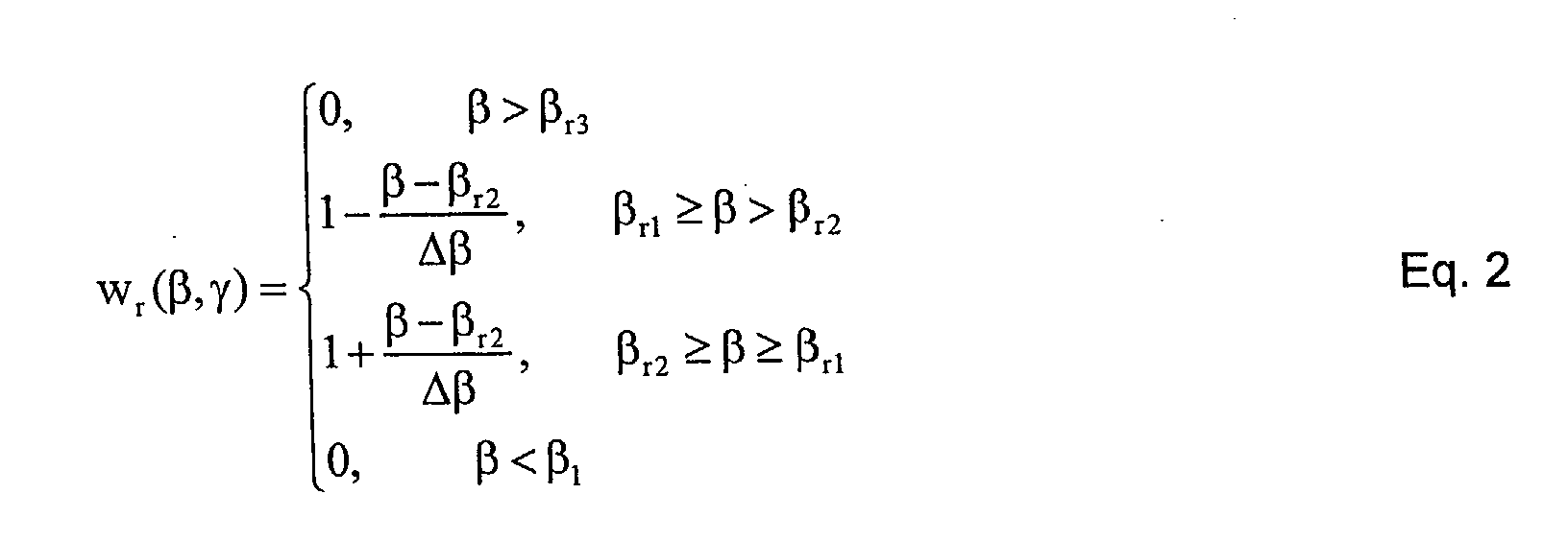
    The helical weighting factor illustrated in Fig. 5 can be generically expressed according to the following equations:
    Figure 00150001
    where, Δβp , and p is the helical pitch, βr1 = tgγ + rΔβ, βr2 = βr1 + Δβ, and βr3 = βr1 + 2Δβ. where β is a gantry angle centered on the selected imaging plane and central within the data corresponding to a specific row, and r is the detector row which ranges from zero to N-1 where N is the number of rows in a detector 44.
    It is instructive in understanding the helical weighting algorithm corresponding to Equations 2 through 5 above to view the sum of the helical weights for all eight detector rows determined via Equations 2 through 5 above at each gantry angle and each fan angle. To this end, assuming approximately 888 fan angles γ per view and 984 separate gantry angles, referring now to Figs. 6 and 7, three dimensional and two dimensional graphs of the summed detector weights for each gantry angle β and each fan angle γ determined according to Equations 2 through 5 are illustrated, respectively. For instance, the summed weights for the gantry and phase angles within region 140 is one. Similarly, the summed weights for the gantry and phase angles within regions 146 and 148 is zero while the summed weights for the gantry and phase angles within regions 142 and 144 ramp from zero to one between regions 146 and 148 and region 140, respectively. Clearly the illustrated summed weighting function is unique.
    2. Conjugate Weighting Process
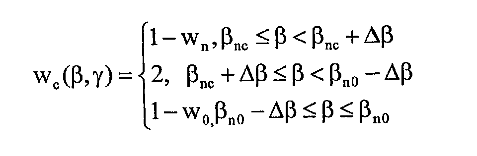
    Where the acquisition system is run at a high helical pitch the data corresponding to the selected image slice plane corresponds to less than 2π gantry rotations about an ROI and therefore it is not possible to reconstruct an accurate image directly using only the helically weighted arrays. Additional weighting has to be performed. To this end, a conjugate weighting function has been developed that can be expressed by the following equations:
    Figure 00160001
    where w0 and wn are helical weighting functions for the first and last detector rows (e.g., R1 and R8 in Fig. 3), and βn0 and βnc are the conjugate parameters (i.e., gantry angles) corresponding to the beginning of the first row and the end of the last row, respectively.
    Referring to Figs. 8 and 9, three and two dimensional graphs similar to those of Figs. 6 and 7 are provided, respectively, that show the final weights after combining the conjugate weights and the helical weights. In Figs. 8 and 9 there are nine separately weighted regions including a region 150 having a weight of two, region 154 having combined weights of one, region 164 having combined weights of one, region 156 having combined weights of zero, region 158 having combined weights of zero, region 162 ramps from zero to one between regions 156 and 164, region 168 ramps from zero to one between regions 158 and 154, region 152 ramps from one to two between regions 164 and 150 and region 160 ramps from one to two between regions 154 and 150. Once again it should be appreciated that the weighting function of Figs. 8 and 9 is unique.
    If the desired slice profile is thicker than the profiles supported by the data and reconstruction algorithms described above, a thicker slice can be derived by summing multiple thin slices within the desired slice profile. If the multiple thin slices by themselves are not of interest, the intermediate step of reconstructing multiple thin slices can be bypassed by performing the corresponding summation early in the projection domain. This reduces the computation load and the image storage load. The resultant weighting functions can be derived by summing corresponding shifted versions of the data planes.
    From the preceding description of the present invention, it is evident that the objects of the invention are attained. Although the invention has been described and illustrated in detail, it is to be clearly understood that the same is intended by way of illustration and example only and is not to be taken by way of limitation. For example, the CT system described herein is a "third generation" system in which both the x-ray source and detector rotate with the gantry. Many other CT systems including "fourth generation" systems wherein the detector is a full-ring stationary detector and only the x-ray source rotates with the gantry, may be used.
    For the sake of good order, various aspects of the invention are set out in the following clauses:-
  • 1. An apparatus for use with a CT imaging system (38) including a radiation source (26) and opposed detector (44) mounted to a gantry (20) on opposite sides of an imaging area, the detector including N separate detector rows arranged perpendicular to a translation axis (48), the apparatus for producing a tomographic slice image through a slice image plane passing through a region of interest (ROI) within an object from a projection data set acquired in a helical scan having a pitch p where the data set includes n separate row data sets corresponding to the n detector rows (R1-R8) and each row data set correlates row views with gantry angles, a central angle β within the projection data set essentially aligned with the slice image plane, the apparatus comprising an image reconstructor configured to:
  • create a separate projection data array (104) for each of the N separate row data sets;
  • apply (112) a helical weighting function to each of the projection data arrays to generate a separate helical weighted array (108) for each projection data array, the weighting function to be applied to each projection data array being:
    Figure 00180001
  • where Δβp , βr1 = tgγ + rΔβ, βr2 = βr1 + Δβ, and βr3 = βr1 + 2Δβ. where tg is a tangent weighting parameter, γ is a fan angle within each beam and r is the detector row number having a value between 0 and N-1; and construct (116) a slice image using the helical weighted arrays.
  • 2. The apparatus of clause 1 wherein the reconstructor (68) is further configured to apply (115) a conjugate weighted function to each of the helical weighted arrays thereby generating a conjugate weighted array (114) for each helical weighted array and wherein the reconstructor is configured to construct the slice image using the conjugate weighted arrays.
  • 3. The apparatus of clause 2 wherein the conjugate weighted function includes the following equation:
    Figure 00190001
    where w0 and wn are helical weighting functions for the first and last detector rows, respectively, and βn0 and βnc are conjugate parameters corresponding to the beginning of the first row and the end of the last row, respectively.
  • 4. The apparatus of clause 3 wherein the reconstructor (68) is configured to use the conjugate weighted arrays to generate the slice image by, for each gantry angle within the slice image plane, adding (118) the conjugate weighted arrays corresponding to each detector row and to the gantry angle to generate a combined weighted array for the angle, filtering the combined weighted arrays and then back-projecting the combined weighted arrays.
  • 5. The apparatus of clause 3 wherein the reconstructor (68) is configured to use the conjugate weighted arrays to generate the slice image by, for the conjugate weighted arrays corresponding to each detector row, filtering and back-projecting (116) the conjugate gated arrays to generate a row specific slice image and then adding the row specific slice images to generate a final slice image (120) within the image plane.
  • 6. The apparatus of clause 1 wherein the reconstructor (68) is further configured to, prior to applying the helical weighting function to each of the projection data arrays, storing the data arrays in a system memory for reconstructing a plurality of slice images.
  • 7. An apparatus for use with a CT imaging system (38) including a radiation source (26) and opposed detector (44) mounted to a gantry (20) on opposite sides of an imaging area, the source generating a fan beam including rays at varying fan beam angles γ, the detector including N separate detector rows (R1-R8) arranged perpendicular to a translation axis (48), the apparatus for producing a tomographic slice image through a slice image plane passing through a region of interest (ROI) within an object from a projection data set acquired in a helical scan having a pitch p where the data set includes N separate row data sets corresponding to the N detector rows and each row data set correlates row views with gantry angles, a central angle β within the projection data set essentially aligned with the slice image plane, the apparatus comprising an image reconstructor (68) configured to:
  • create (102) a separate projection data array for each of the N separate row data sets;
  • apply (112) a helical weighting function to each of the projection data arrays to generate a separate helical weighted array for each projection data array wherein the weighting function corresponding to each row view is dependent on both the gantry angle and the fan angle; and
  • construct (116) a slice image using the helical weighted arrays.
  • 8. The apparatus of clause 7 wherein the reconstructor (68) is further configured to apply (115) a conjugate weighted (110) function to each of the helical weighted arrays thereby generating a conjugate weighted array (114) for each helical weighted array and wherein the reconstructor is configured to construct the slice image (120) using the conjugate weighted arrays.
  • 9. The apparatus of clause 8 wherein the conjugate weighted function includes the following equation:
    Figure 00200001
    where w0 and wn are helical weighting functions for the first and last detector rows, respectively, and βn0 and βnc are conjugate parameters corresponding to the beginning of the first row and the end of the last row, respectively.
  • 10. The apparatus of clause 9 wherein the reconstructor (68) is configured to use the conjugate weighted arrays to generate the slice image by, for each gantry angle within the slice image plane, adding (118) the conjugate weighted arrays corresponding to each detector row and to the gantry angle to generate a combined weighted array for the angle, filtering the combined weighted arrays and then back-projecting the combined weighted arrays.
  • 11. The apparatus of clause 9 wherein the reconstructor (68) is configured to use the conjugate weighted arrays to generate the slice image by, for the conjugate weighted arrays corresponding to each detector row, filtering and back-projecting the conjugate gated arrays to generate a row specific slice image and then adding the row specific slice images to generate a final slice image within the image plane.
  • 12. A method for use with a CT imaging system (38) including a radiation source (26) and opposed detector (44) mounted to a gantry (20) on opposite sides of an imaging area, the detector including N separate detector rows (R1-R8) arranged perpendicular to a translation axis (48), the method for producing a tomographic slice image through a slice image plane passing through a region of interest (ROI) within an object from a projection data set acquired in a helical scan having a pitch p where the data set includes N separate row data sets corresponding to the N detector rows and each row data set correlates row views with gantry angles, a central angle β within the projection data set essentially aligned with the slice image plane, the method comprising the steps of:
  • creating (102) a separate projection data array for each of the N separate row data sets;
  • applying (112) a helical weighting function (106) to each of the projection data arrays generated in step (a) to generate a separate helical weighted array for each projection data array, the weighting function to be applied to each projection data array being:
    Figure 00210001
  • where Δβp , βr1 = tgγ + rΔβ, βr2 = βr1 + Δβ, and βr3 = βr1 + 2Δβ. where tg is a tangent weighting parameter, γ is a fan angle within each beam and r is the detector row number having a value between 0 and N-1; and
       constructing (116) a slice image (120) using the helical weighted arrays.
  • 13. The method of clause 12 further including the step of applying (115) a conjugate weighted function (110) to each of the helical weighted arrays thereby generating a conjugate weighted array (114) for each helical weighted array and wherein the step of constructing includes constructing (118) the slice image using the conjugate weighted arrays.
  • 14. The method of clause 13 wherein the conjugate weighted function includes the following equation:
    Figure 00220001
    where w0 and wn are helical weighting functions for the first and last detector rows, respectively, and βn0 and βnc are conjugate parameters corresponding to the beginning of the first row and the end of the last row, respectively.
  • 15. The method of clause 14 wherein the step of using the conjugate weighted arrays to generate the slice image includes, for each gantry angle within the slice image plane, adding (118) the conjugate weighted arrays corresponding to each detector row and to the gantry angle to generate a combined weighted array for the angle, filtering (116) the combined weighted arrays and then back-projecting (116) the combined weighted arrays.
  • 16. The method of clause 14 wherein the step of using the conjugate weighted arrays to generate the slice image includes, for the conjugate weighted arrays corresponding to each detector row, filtering and back-projecting the conjugate gated arrays to generate a row specific slice image and then adding the row specific slice images to generate a final slice image within the image plane.
  • 17. The method of clause 12 further including the step of, prior to applying the helical weighting function to each of the projection data arrays, storing the data arrays in a system memory for reconstructing a plurality of slice images.
  • 18. A method for use with a CT imaging system (38) including a radiation source (26) and opposed detector (44) mounted to a gantry (20) on opposite sides of an imaging area, the source generating a fan beam including rays at varying fan beam angles γ, the detector including N separate detector rows (R1-R8) arranged perpendicular to a translation axis (48), the method for producing a tomographic slice image through a slice image plane passing through a region of interest (ROI) within an object from a projection data set acquired in a helical scan having a pitch p where the data set includes N separate row data sets corresponding to the N detector rows and each row data set correlates row views with gantry angles, a central angle β within the projection data set essentially aligned with the slice image plane, the method comprising the steps of:
  • creating (102) a separate projection data array (104) for each of the N separate row data sets;
  • applying (112) a helical weighting function (106) to each of the projection data arrays to generate a separate helical weighted array for each projection data array wherein the weighting function corresponding to each row view is dependent on both the gantry angle and the fan angle; and
  • constructing (116) a slice image using the helical weighted arrays.
  • 19. The method of clause 18 further including the step of applying (115) a conjugate weighted function (110) to each of the helical weighted arrays thereby generating a conjugate weighted array (114) for each helical weighted array and wherein the step of constructing the slice image includes using the conjugate weighted arrays.
  • 20. The method of clause 19 wherein the conjugate weighted function includes the following equation:
    Figure 00240001
  • where w0 and wn are helical weighting functions for the first and last detector rows, respectively, and βn0 and βnc are conjugate parameters corresponding to the beginning of the first row and the end of the last row, respectively.

    Claims (10)

    1. An apparatus for use with a CT imaging system (38) including a radiation source (26) and opposed detector (44) mounted to a gantry (20) on opposite sides of an imaging area, the detector including n separate detector rows arranged perpendicular to a translation axis (48), the apparatus for producing a tomographic slice image through a slice image plane passing through a region of interest (ROI) within an object from a projection data set acquired in a helical scan having a pitch p where the data set includes n separate row data sets corresponding to the n detector rows (R1-R8) and each row data set correlates row views with gantry angles, a central angle β within the projection data set essentially aligned with the slice image plane, the apparatus comprising an image reconstructor configured to:
      create a separate projection data array (104) for each of the n separate row data sets;
      apply (112) a helical weighting function to each of the projection data arrays to generate a separate helical weighted array (108) for each projection data array, the weighting function to be applied to each projection data array being:
      Figure 00250001
      where Δβp , βr1 = tgγ + rΔβ, βr2 = βr1 + Δβ, and βr3 = βr1 + 2Δβ. where tg is a tangent weighting parameter, γ is a fan angle within each beam and r is the detector row number having a value between 0 and N-1; and construct (116) a slice image using the helical weighted arrays.
    2. The apparatus of claim 1 wherein the reconstructor (68) is further configured to apply (115) a conjugate weighted function to each of the helical weighted arrays thereby generating a conjugate weighted array (114) for each helical weighted array and wherein the reconstructor is configured to construct the slice image using the conjugate weighted arrays.
    3. The apparatus of claim 2 wherein the conjugate weighted function includes the following equation:
      Figure 00260001
      where w0 and wn are helical weighting functions for the first and last detector rows, respectively, and βn0 and βnc are conjugate parameters corresponding to the beginning of the first row and the end of the last row, respectively.
    4. An apparatus for use with a CT imaging system (38) including a radiation source (26) and opposed detector (44) mounted to a gantry (20) on opposite sides of an imaging area, the source generating a fan beam including rays at varying fan beam angles γ, the detector including N separate detector rows (R1-R8) arranged perpendicular to a translation axis (48), the apparatus for producing a tomographic slice image through a slice image plane passing through a region of interest (ROI) within an object from a projection data set acquired in a helical scan having a pitch p where the data set includes N separate row data sets corresponding to the N detector rows and each row data set correlates row views with gantry angles, a central angle β within the projection data set essentially aligned with the slice image plane, the apparatus comprising an image reconstructor (68) configured to:
      create (102) a separate projection data array for each of the N separate row data sets;
      apply (112) a helical weighting function to each of the projection data arrays to generate a separate helical weighted array for each projection data array wherein the weighting function corresponding to each row view is dependent on both the gantry angle and the fan angle; and
      construct (116) a slice image using the helical weighted arrays.
    5. The apparatus of claim 4 wherein the reconstructor (68) is further configured to apply (115) a conjugate weighted (110) function to each of the helical weighted arrays thereby generating a conjugate weighted array (114) for each helical weighted array and wherein the reconstructor is configured to construct the slice image (120) using the conjugate weighted arrays.
    6. The apparatus of claim 5 wherein the conjugate weighted function includes the following equation:
      Figure 00270001
      where w0 and wn are helical weighting functions for the first and last detector rows, respectively, and βn0 and βnc are conjugate parameters corresponding to the beginning of the first row and the end of the last row, respectively.
    7. A method for use with a CT imaging system (38) including a radiation source (26) and opposed detector (44) mounted to a gantry (20) on opposite sides of an imaging area, the detector including N separate detector rows (R1-R8) arranged perpendicular to a translation axis (48), the method for producing a tomographic slice image through a slice image plane passing through a region of interest (ROI) within an object from a projection data set acquired in a helical scan having a pitch p where the data set includes N separate row data sets corresponding to the N detector rows and each row data set correlates row views with gantry angles, a central angle β within the projection data set essentially aligned with the slice image plane, the method comprising the steps of:
      creating (102) a separate projection data array for each of the N separate row data sets;
      applying (112) a helical weighting function (106) to each of the projection data arrays generated in step (a) to generate a separate helical weighted array for each projection data array, the weighting function to be applied to each projection data array being:
      Figure 00280001
      where Δβp , βr1 = tgγ + rΔβ, βr2 = βr1 + Δβ, and βr3 = βr1 + 2Δβ. where tg is a tangent weighting parameter, γ is a fan angle within each beam and r is the detector row number having a value between 0 and N-1; and
         constructing (116) a slice image (120) using the helical weighted arrays.
    8. The method of claim 7 further including the step of applying (115) a conjugate weighted function (110) to each of the helical weighted arrays thereby generating a conjugate weighted array (114) for each helical weighted array and wherein the step of constructing includes constructing (118) the slice image using the conjugate weighted arrays.
    9. A method for use with a CT imaging system (38) including a radiation source (26) and opposed detector (44) mounted to a gantry (20) on opposite sides of an imaging area, the source generating a fan beam including rays at varying fan beam angles γ, the detector including N separate detector rows (R1-R8) arranged perpendicular to a translation axis (48), the method for producing a tomographic slice image through a slice image plane passing through a region of interest (ROI) within an object from a projection data set acquired in a helical scan having a pitch p where the data set includes N separate row data sets corresponding to the N detector rows and each row data set correlates row views with gantry angles, a central angle β within the projection data set essentially aligned with the slice image plane, the method comprising the steps of:
      creating (102) a separate projection data array (104) for each of the N separate row data sets;
      applying (112) a helical weighting function (106) to each of the projection data arrays to generate a separate helical weighted array for each projection data array wherein the weighting function corresponding to each row view is dependent on both the gantry angle and the fan angle; and
      constructing (116) a slice image using the helical weighted arrays.
    10. The method of claim 9 further including the step of applying (115) a conjugate weighted function (110) to each of the helical weighted arrays thereby generating a conjugate weighted array (114) for each helical weighted array and wherein the step of constructing the slice image includes using the conjugate weighted arrays.
    EP02257741A 2001-11-09 2002-11-07 Row-wise full helical view weighting method and apparatus for CT scanners Withdrawn EP1324271A3 (en)

    Applications Claiming Priority (2)

    Application Number Priority Date Filing Date Title
    US37032 2001-11-09
    US10/037,032 US6522714B1 (en) 2001-11-09 2001-11-09 Row-wise full helical view weighting method and apparatus for CT scanners

    Publications (2)

    Publication Number Publication Date
    EP1324271A2 true EP1324271A2 (en) 2003-07-02
    EP1324271A3 EP1324271A3 (en) 2005-04-27

    Family

    ID=21892072

    Family Applications (1)

    Application Number Title Priority Date Filing Date
    EP02257741A Withdrawn EP1324271A3 (en) 2001-11-09 2002-11-07 Row-wise full helical view weighting method and apparatus for CT scanners

    Country Status (3)

    Country Link
    US (1) US6522714B1 (en)
    EP (1) EP1324271A3 (en)
    JP (1) JP2003164444A (en)

    Families Citing this family (14)

    * Cited by examiner, † Cited by third party
    Publication number Priority date Publication date Assignee Title
    JP4030827B2 (en) * 2002-08-13 2008-01-09 ジーイー・メディカル・システムズ・グローバル・テクノロジー・カンパニー・エルエルシー Projection data creation method, pixel data creation method, and multi-detector X-ray CT apparatus
    US7013034B2 (en) * 2002-10-10 2006-03-14 Ge Medical Systems Global Technology Company, Llc Methods and apparatus for reconstructing an image of an object
    JP4585167B2 (en) * 2002-11-29 2010-11-24 東芝医用システムエンジニアリング株式会社 X-ray computed tomography system
    US6999555B2 (en) * 2003-09-15 2006-02-14 Varian Medical Systems Imaging Laboratory Gmbh Systems and methods for processing data
    US6977984B2 (en) * 2003-10-07 2005-12-20 Ge Medical Systems Global Technology Company, Llc Methods and apparatus for dynamical helical scanned image production
    US7672421B2 (en) * 2005-10-12 2010-03-02 Siemens Medical Solutions Usa, Inc. Reduction of streak artifacts in low dose CT imaging through multi image compounding
    US7515675B2 (en) 2005-12-07 2009-04-07 Ge Security, Inc. Apparatus and method for providing a near-parallel projection from helical scan data
    US7492856B2 (en) 2005-12-07 2009-02-17 Ge Security, Inc. Apparatus and method for providing an orthographic projection from helical scan data
    JP2007236662A (en) * 2006-03-09 2007-09-20 Ge Medical Systems Global Technology Co Llc X-ray ct system, its x-ray ct image reconstitution method and x-ray ct image photographing method
    DE102012217163B4 (en) * 2012-09-24 2022-06-02 Siemens Healthcare Gmbh Method for the reconstruction of CT image data with weighted back projection, including computing unit and CT system for this method
    US9406107B2 (en) * 2013-12-18 2016-08-02 General Electric Company System and method of computed tomography signal restoration via noise reduction
    US12406410B2 (en) * 2017-08-18 2025-09-02 Shanghai United Imaging Healthcare Co., Ltd. System and method for reconstructing an image
    WO2019033390A1 (en) * 2017-08-18 2019-02-21 Shenzhen United Imaging Healthcare Co., Ltd. System and method for reconstructing images
    CN115770060B (en) * 2022-12-29 2026-01-02 中科超精(南京)科技有限公司 A method and device for controlling high-speed cone-beam CT with continuous angle tracking

    Family Cites Families (5)

    * Cited by examiner, † Cited by third party
    Publication number Priority date Publication date Assignee Title
    US5396418A (en) * 1988-10-20 1995-03-07 Picker International, Inc. Four dimensional spiral volume imaging using fast retrace
    JP3637074B2 (en) * 1992-12-15 2005-04-06 株式会社東芝 Helical scan computed tomography system
    US5541970A (en) * 1995-05-09 1996-07-30 General Electric Company Image reconstruction for a CT system implementing a four fan beam helical scan
    US5828718A (en) * 1996-11-27 1998-10-27 Analogic Corporation Method and apparatus for helical computed tomography scanning with asymmetric detector system
    JP4726287B2 (en) * 1999-10-20 2011-07-20 株式会社日立メディコ Multi-slice X-ray CT system

    Also Published As

    Publication number Publication date
    EP1324271A3 (en) 2005-04-27
    JP2003164444A (en) 2003-06-10
    US6522714B1 (en) 2003-02-18

    Similar Documents

    Publication Publication Date Title
    US7327822B2 (en) Methods, apparatus, and software for reconstructing an image
    US6452996B1 (en) Methods and apparatus utilizing generalized helical interpolation algorithm
    US6678346B2 (en) Cone-beam CT scanner with image reconstruction using multiple sub-images
    EP0430549B1 (en) Helical scan computed tomography
    EP1113396B1 (en) Method and apparauts for multislice CT using partial scan
    EP0964643B1 (en) Helical scanner with variably oriented scan axis
    US6301325B1 (en) Half-scan algorithm for use with a high speed multi-row fan beam helical detector
    EP1599836B1 (en) System and method for helical cone-beam computed tomography with exact reconstruction
    JPH09224930A (en) System for generating tomographic images of an object and volumetric computer tomography apparatus
    US6904117B2 (en) Tilted gantry helical cone-beam Feldkamp reconstruction for multislice CT
    US6490335B1 (en) Helical segment image reconstruction
    US6522714B1 (en) Row-wise full helical view weighting method and apparatus for CT scanners
    JP2001224588A (en) Method and apparatus for computed tomography imaging with reduced exposure
    JPH09285460A (en) System for generating tomographic images of objects
    US6381297B1 (en) High pitch reconstruction of multislice CT scans
    US6339632B1 (en) Multi slice single filtering helical weighting method and apparatus to use the same
    US6173032B1 (en) Methods and apparatus for image reconstruction
    US7215734B2 (en) Method and system for three-dimensional reconstruction of images
    US6885764B2 (en) High Speed Z-smoothing method and apparatus for CT imaging system
    JP2000023966A (en) Spiral reconstruction algorithm
    JP2002034970A (en) Method and apparatus for helical reconstruction of a multi-slice CT scan
    JPH0998968A (en) Method and apparatus for creating a tomographic image of an object
    US6647084B1 (en) Method and apparatus for filtering projection data of a helical scan
    EP0982680A2 (en) Systems, methods and apparatus for reconstructing images
    US6999550B2 (en) Method and apparatus for obtaining data for reconstructing images of an object

    Legal Events

    Date Code Title Description
    PUAI Public reference made under article 153(3) epc to a published international application that has entered the european phase

    Free format text: ORIGINAL CODE: 0009012

    AK Designated contracting states

    Designated state(s): AT BE BG CH CY CZ DE DK EE ES FI FR GB GR IE IT LI LU MC NL PT SE SK TR

    AX Request for extension of the european patent

    Extension state: AL LT LV MK RO SI

    PUAL Search report despatched

    Free format text: ORIGINAL CODE: 0009013

    AK Designated contracting states

    Kind code of ref document: A3

    Designated state(s): AT BE BG CH CY CZ DE DK EE ES FI FR GB GR IE IT LI LU MC NL PT SE SK TR

    AX Request for extension of the european patent

    Extension state: AL LT LV MK RO SI

    17P Request for examination filed

    Effective date: 20051027

    AKX Designation fees paid

    Designated state(s): DE NL

    17Q First examination report despatched

    Effective date: 20061201

    STAA Information on the status of an ep patent application or granted ep patent

    Free format text: STATUS: THE APPLICATION IS DEEMED TO BE WITHDRAWN

    18D Application deemed to be withdrawn

    Effective date: 20070412