EP1324265A2 - Method and system for improving an image characteristic based on image content - Google Patents
Method and system for improving an image characteristic based on image content Download PDFInfo
- Publication number
- EP1324265A2 EP1324265A2 EP02079890A EP02079890A EP1324265A2 EP 1324265 A2 EP1324265 A2 EP 1324265A2 EP 02079890 A EP02079890 A EP 02079890A EP 02079890 A EP02079890 A EP 02079890A EP 1324265 A2 EP1324265 A2 EP 1324265A2
- Authority
- EP
- European Patent Office
- Prior art keywords
- image
- belief
- parameter
- pixels
- characteristic
- Prior art date
- Legal status (The legal status is an assumption and is not a legal conclusion. Google has not performed a legal analysis and makes no representation as to the accuracy of the status listed.)
- Granted
Links
Images


Classifications
-
- G—PHYSICS
- G06—COMPUTING OR CALCULATING; COUNTING
- G06T—IMAGE DATA PROCESSING OR GENERATION, IN GENERAL
- G06T5/00—Image enhancement or restoration
- G06T5/73—Deblurring; Sharpening
- G06T5/75—Unsharp masking
-
- G—PHYSICS
- G06—COMPUTING OR CALCULATING; COUNTING
- G06T—IMAGE DATA PROCESSING OR GENERATION, IN GENERAL
- G06T2207/00—Indexing scheme for image analysis or image enhancement
- G06T2207/20—Special algorithmic details
- G06T2207/20004—Adaptive image processing
- G06T2207/20008—Globally adaptive
Definitions
- the invention relates generally to the field of digital image processing and, more particularly, to a method for relating a processing parameter to the contents of an image.
- an unsharp image is generated by convolution of the image with a lowpass filter (i.e., the unsharp image is given by i(x,y)**b(x,y)).
- the highpass, or fringe, data is generated by subtracting the unsharp image from the original image (i.e., the highpass data is found with i(x,y) - i(x,y)**b(x,y)).
- This highpass data is then modified by either a scale factor ⁇ or a fringe function f() or both.
- the modified highpass data is summed with either the original image or the unsharp image to produce a sharpened image.
- a similar sharpening effect can be achieved by modification of the image in the frequency domain (for example, the FFT domain) as is well known in the art of digital signal processing.
- the space domain e.g., convolution methods
- the frequency domain methods of enhancing image sharpness are shift invariant methods. In other words, the sharpening process is invariant to the location within the image.
- the quality of the resulting image often varies depending on the image content. For example, using the unsharp mask algorithm may produce a pleasing result for an image of a building. However, using the same algorithm may result in the undesirable appearance of oversharpening for an image of a human face (e.g., blemishes may be enhanced).
- the scale factor parameter may be modified individually for each scene by a human operator, but this is an expensive process.
- a method of improving a characteristic of an image according to its material content comprises the steps of: providing an image comprised of image pixels; generating a belief map corresponding spatially to the image pixels, wherein the belief map includes belief values indicating the likelihood that respective pixels are representative of a particular material; generating an improvement parameter from the belief map, wherein the improvement parameter is applied uniformly to the image pixels; and using the improvement parameter to improve the characteristic of the image.
- the present invention has the advantage that the global level of a particular characteristic of an image can be varied depending on the detected materials within the image. Where the characteristic is sharpness, rather than tuning a system to sharpen all images at a conservative level for fear of creating sharpening artifacts in some images, the system according to the present invention automatically determines the sharpening for each image, conservatively sharpening sensitive images and aggressively sharpening non-sensitive images. Specifically, the system of the present invention conservatively sharpens images in which human flesh is detected and aggressively sharpens images in which human flesh is not detected. In another aspect, the system according to the present invention conservatively reduces noise in areas of images where noise reduction can lead to objectionable artifacts, such as in images of vegetation, and aggressively reduces noise in images in which such sensitive material content is not detected.
- FIG. 1 is a block diagram illustrating a technique for improving an image according to a first embodiment of the invention.
- FIG. 2 is an example of the type of image processed according to the image improvement technique shown in Figure 1.
- FIG. 3 is an example of a belief map generated according to the image improvement technique shown in Figure 1 for the image shown in Figure 2 when the target material is human flesh.
- FIG. 4 is a representation of a function g(z) used to determine a scale factor ⁇ for the image improvement technique shown in Figure 1.
- FIG. 5 is a representation of another function h(z) used to determine a scale factor ⁇ for the image improvement technique shown in Figure 1.
- FIG. 6 is a block diagram illustrating a technique for improving an image according to a second embodiment of the invention.
- the computer program may be stored in a computer readable storage medium, which may comprise, for example; magnetic storage media such as a magnetic disk (such as a hard drive or a floppy disk) or magnetic tape; optical storage media such as an optical disc, optical tape, or machine readable bar code; solid state electronic storage devices such as random access memory (RAM), or read only memory (ROM); or any other physical device or medium employed to store a computer program.
- a computer readable storage medium may comprise, for example; magnetic storage media such as a magnetic disk (such as a hard drive or a floppy disk) or magnetic tape; optical storage media such as an optical disc, optical tape, or machine readable bar code; solid state electronic storage devices such as random access memory (RAM), or read only memory (ROM); or any other physical device or medium employed to store a computer program.
- a digital image is typically a two-dimensional array of numbers representing red, green, and blue pixel values or monochrome pixel values corresponding to light intensities.
- the value of a pixel of a digital image located at coordinates ( x,y ), referring to the x th row and the y th column of a digital image shall herein comprise a triad of values [r(x,y), g(x,y), b(x,y)] respectively referring to the values of the red, green and blue digital image channels at location ( x,y ).
- a digital image may be considered as comprising a certain number of digital image channels.
- the image comprises three channels, namely, red, green and blue spectral channels.
- a first embodiment of the present invention is illustrated for processing an image with a specific image processing path in order obtain an enhanced output image.
- the present invention performs a shift invariant improvement to an image, the magnitude of the improvement being determined by the material content of objects within the image.
- the improvement applied to successive images may vary depending on the image content.
- the magnitude of the improvement applied to any particular image is selected in order to be appropriate for the image content.
- the present invention performs a shift invariant sharpening to an image, the magnitude of the sharpening being determined by the objects within the image.
- the sharpening applied to successive images may vary depending on the image content, and the magnitude of the sharpening applied to any particular image is selected in order to be appropriate for the image content.
- Fig. 1 illustrates an image i(x,y) having x o rows and y o columns that is input to an image subsampler 2 for reducing the number of pixels contained in the image and therefore decreasing the processing time required by the present invention to determine the sharpening parameter.
- Many other methods of creating small images from larger images are known in the art of image processing and can be used as the image subsampler 2 . (The preceding examples are not intended as a limitation; in fact, the image subsampler may be omitted if the additional processing can be tolerated.)
- the image output from the image subsampler 2 is then input to a material detector 4 for the creation of a belief map, indicating the belief that particular pixels or regions of pixels represent a given target material.
- the target material is selected as the material to which the image sharpening is sensitive.
- the material detector 4 outputs a belief map M(m,n), preferably having the same pixel dimensions in terms of rows and columns as the image input to the material detector 4 .
- the belief map indicates the belief that particular pixels represent the target material.
- the belief is preferably represented as a probability. For example, each pixel value M(m,n) is equal to 100 * P( that pixel (m,n) of the low resolution image represents target material ), where P( A ) represents the probability of event A .
- each pixel value M(m,n) may represent a binary classification indicating belief.
- a pixel value of 1 in the belief map may represent the belief that the pixel represents the target material and a pixel value of 0 may represent the belief that the pixel does not represent the target material.
- the target material is human flesh.
- U. S. Serial No. 09/904,366, entitled "A Method for Processing a Digital Image to Adjust Brightness” and filed on July 12, 2001 in the names of M. W. Dupin and J. Luo a method is described of creating a belief map indicating the belief for a target material of flesh. Additionally, methods of creating belief maps for a target material of human flesh are described in the following articles: K.
- L,s,t) Pr(Skin
- the collection of probabilities for all pixels forms a skin-tone probability distribution for the input image.
- the skin-tone probability distribution is thresholded to create a binary map such that each pixel is designated as either skin-tone or non skin-tone.
- a face detection algorithm can be initially used to find human face regions in the input color digital image. Thereupon, regions of skin-tone colors may be extracted from the detected face regions.
- regions of skin-tone colors may be extracted from the detected face regions.
- Figs. 2 and 3 An example of the methodology is shown in Figs. 2 and 3, where Fig. 2 shows an image of several people and Fig. 3 shows the associated belief map, when the target material is human flesh.
- the background 12 of the image is made up of the pixels having a belief of zero that the corresponding pixel in the low resolution image represents the target material (human flesh). If the material detector 4 detects that all pixels of the low resolution image have low probability of representing the target material, then the entire belief map will be background 12 (all zeros in the preferred encoding).
- Fig. 3 shows several regions made up of pixels having nonzero belief. For example, region 16 corresponds to a face in the low resolution image, and for example may have a high belief value of 95. Region 14 corresponds to an arm, and may have a belief value of 60.
- Region 18 incorrectly has a belief value of 40, indicating a belief that the tree branch may be human flesh. Such an incorrect belief value is a false positive.
- automatic detection algorithms such as the material detector 4 produce false positives such as region 18 as well as false negatives, (e.g. incorrectly classifying genuine flesh pixels as background 12 ).
- the target material could be the material content of other types of objects in the image, such as human faces, sky, or any other material for which an automated method exists for determining material belief from an image.
- Human face detection is described in many articles, for example, see B. Heisele, T. Poggio, M. Pontil, "Face Detection in Still Gray Images," MIT Artificial Intelligence Lab , Memo 1687, May 2000.
- commonly-assigned copending U. S. Serial No. 09/450,190 (entitled “Method for Detecting Sky in Images” and filed November 29, 1999 in the names of J. Luo and S. Etz) describes the creation of belief maps when the target material is blue sky.
- the belief map is then input to a map analyzer 8 .
- the map analyzer 8 analyses the belief map and outputs the recommendation for the sharpening of the image as one or more sharpening parameters.
- a sharpening parameter is any parameter which directly relates to the level or strength of sharpening applied to an image.
- the map analyzer 8 outputs a scale factor ⁇ derived from an analysis of the belief map.
- the sharpening parameters are a function of the belief map.
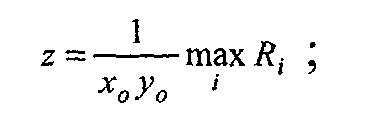
- the scale factor ⁇ is a function of the belief map M(m,n) and is preferably derived as follows: where:
- the scale factor ⁇ is determined based on the maximum belief of flesh contained in the belief map. Note that ⁇ material and ⁇ non-material may themselves be functions of characteristics of the image or the imaging system. For example, ⁇ material and ⁇ non-material may be decreased for high speed films because of grain.
- the scale factor may be determined based on other characteristics of the belief map.
- the scale factor may be determined based on other characteristics of the belief map. It has been observed that large flesh areas are most sensitive to the oversharpening because blemishes quickly become apparent. However, when the flesh regions are small, generally the image can be sharpened more without the appearance of objectionable artifacts. As shown in Fig. 3, the preferred material detector 4 is described in the aforementioned commonly-assigned, copending U. S. Serial No. 09/904,366, where Dupin and Luo return a belief map generally consisting of a background area 12 wherein all pixels have a value of 0 indicating the probability that the pixels represent the target material (human flesh) is estimated to be 0.
- each belief region having non-zero belief may be extracted from the belief map.
- the size of region 16 is greater than the size of region 14 which is greater than the size of region 18 .
- the size of each belief region may be determined by any number of methods, including one of the several methods described herein. For instance, the size may be determined by counting the number of pixels belong to each belief region.
- the size may be determined by taking the product of the number of pixels belonging to each belief region and the associated value within the belief map of each belief region.
- the sharpening parameter(s) ⁇ determined by the map analyzer 8 is then input to a sharpener 10 . While in the present embodiment of the invention the sharpening parameter is the scale factor ⁇ , the function of the map analyzer 8 is without such limitation and other sharpness related determinations would be evident to those of ordinary skill in the art. For example, the filter used in the sharpening convolution performed by the sharpener 10 could be determined by the map analyzer 8 based on an analysis of the belief map.
- the sharpener 10 inputs the sharpening parameter(s) and applies a sharpening algorithm to the image, utilizing the sharpening parameter(s) in order to produce an enhanced output image having improved sharpness without producing objectionable sharpness artifacts.
- the sharpener 10 applies an unsharp masking algorithm to the image using the determined value of ⁇ in order to produce the enhanced image.
- unsharp masking such as provided by Eq. (1)
- the unsharp mask process can be applied to each channel of the color image.
- the unsharp mask process is applied in the following manner, commonly known in the art:
- Eq. (1) and the present invention generally describe the sharpening applied to the image as being performed by an unsharp mask, that is not necessarily the case.
- the unsharp mask process can always be reconfigured as a single filter than can be applied with convolution to the image and produce results identical to the unsharp mask.
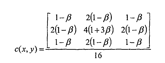
- the filter coefficients of b(x,y) are given as:
- Application of a filter c(x,y) with a convolution having coefficients given as will produce identical results compared with using filter b(x,y) in the unsharp mask of Equation (1).
- Such modifications to the preferred embodiment by the grouping of operations in the sharpener 10 such as can be determined by methods well known in algebra and digital signal processing will be evident to those of skill in this art and are within the scope of the present invention.
- a filter 20 is applied according to a parameter determined by the map analyzer 8.
- the filter is applied uniformly across the image pixels, according to the filter parameter output from the map analyzer 8.
- the image characteristic is not sharpness and the filter is not a sharpening filter.
- the image characteristic is related to another type of improvement and the filter is another type of filter, for example the image characteristic is noise and the filter is a noise reduction filter.
- Noise reduction filters are well described in the art of image processing. For example, Jong-Sen Lee describes the sigma filter in the paper "Digital Image Smoothing and the Sigma Filter," Computer Vision, Graphics, and Image Processing, 24, 255-269, 1983.
- the sigma filter replaces a central pixel of a neighborhood with all those pixels within ⁇ code values of intensity from the central pixel.
- the parameter ⁇ may be selected by the map analyzer 8 in a manner similar to the way that the parameter ⁇ was determined.
- the material content that is analyzed may be the same as that analyzed for sharpness, or it may be some other material content especially sensitive to noise. For example, when the target material is vegetation, the map analyzer 8 may output a small value of ⁇ for images containing regions having high belief and large value of ⁇ for images having no regions with high belief.
Landscapes
- Physics & Mathematics (AREA)
- General Physics & Mathematics (AREA)
- Engineering & Computer Science (AREA)
- Theoretical Computer Science (AREA)
- Image Processing (AREA)
- Facsimile Image Signal Circuits (AREA)
Abstract
Description


g(z) is a function used to convert the average value of the belief map into the scale factor β. An example of the function g(z) is shown in Fig. 4.
- Assuming the input image is a color image consisting of red, green, and blue color channels, a matrix is first applied to the image in order to produce a luminance channel and two or more color difference channels. Next the unsharp mask process is applied to the luminance channel. Finally, an inverse matrix is applied to the several channels, generating an enhanced color image.
- Additionally, the unsharp mask process may be applied to only a single image channel (e.g. the green channel), and the modified fringe data may be summed with each color channel in order to generate an enhanced color image. These and other similar modifications and enhancements to the unsharp mask process would be well understood by those of skill in this art. Since the particularities of their usage are not fundamentally related to the method of selecting sharpening parameters for a shift invariant sharpening, their particular application does not act to in any way limit the scope of the invention.

Claims (13)
- A method of improving a characteristic of an image according to its material content, said method comprising the steps of:providing an image comprised of image pixels;generating a belief map corresponding spatially to the image pixels, wherein the belief map includes belief values indicating the likelihood that respective pixels are representative of a particular material;generating an improvement parameter from the belief values of the belief map, wherein the improvement parameter is proportional to the belief values and applied uniformly to the image pixels; andusing the improvement parameter to improve the characteristic of the image.
- The method as claimed in claim 1 wherein the characteristic is sharpness and the improvement parameter is a sharpening parameter.
- The method as claimed in claim 2 wherein the step of using the improvement parameter comprises performing sharpening with an unsharp mask operation.
- The method as claimed in claim 3 wherein the sharpening parameter is a scale factor used in the unsharp mask operation.
- The method as claimed in claim 1 wherein the characteristic is noise and the improvement parameter is a noise parameter.
- The method as claimed in claim 5 wherein the step of using the improvement parameter comprises performing noise reduction with a sigma filter.
- The method as claimed in claim 1 wherein the step of generating a belief map comprises the steps of:detecting pixels that represent the particular material; andproducing a belief map from the detected pixels.
- The method as claimed in claim 1 wherein the particular material is selected from the group including faces, flesh, sky and vegetation and the improvement parameter conditions the amount of improvement upon a characteristic of the belief values in the belief map that represent the particular material.
- The method as claimed in claim 1 wherein the improvement parameter is proportional to a maximum belief value.
- The method as claimed in claim 1 wherein the improvement parameter is proportional to an average belief value.
- A system for improving a characteristic of an image according to its material content, said system comprising:an image generator providing an image comprised of image pixels;a material detector generating a belief map corresponding spatially to the image pixels, wherein the belief map includes belief values indicating the likelihood that respective pixels are representative of a particular material;a map analyzer generating an improvement parameter from the belief values of the belief map, wherein the improvement parameter is proportional to a characteristic of the belief values and applied uniformly to the image pixels; anda processor using the improvement parameter to improve the characteristic of the image.
- The system as claimed in claim 11 wherein the characteristic is sharpness and the improvement parameter is a sharpening parameter.
- The system as claimed in claim 11 wherein the characteristic is noise and the improvement parameter is a noise parameter.
Applications Claiming Priority (2)
| Application Number | Priority Date | Filing Date | Title |
|---|---|---|---|
| US20031 | 2001-12-07 | ||
| US10/020,031 US7050636B2 (en) | 2001-12-07 | 2001-12-07 | Method and system for improving an image characteristic based on image content |
Publications (3)
| Publication Number | Publication Date |
|---|---|
| EP1324265A2 true EP1324265A2 (en) | 2003-07-02 |
| EP1324265A3 EP1324265A3 (en) | 2006-08-16 |
| EP1324265B1 EP1324265B1 (en) | 2010-02-10 |
Family
ID=21796353
Family Applications (1)
| Application Number | Title | Priority Date | Filing Date |
|---|---|---|---|
| EP02079890A Expired - Lifetime EP1324265B1 (en) | 2001-12-07 | 2002-11-25 | Method and system for sharpening an image based on image content |
Country Status (4)
| Country | Link |
|---|---|
| US (1) | US7050636B2 (en) |
| EP (1) | EP1324265B1 (en) |
| JP (1) | JP4498671B2 (en) |
| DE (1) | DE60235292D1 (en) |
Families Citing this family (32)
| Publication number | Priority date | Publication date | Assignee | Title |
|---|---|---|---|---|
| US7064740B2 (en) * | 2001-11-09 | 2006-06-20 | Sharp Laboratories Of America, Inc. | Backlit display with improved dynamic range |
| US7092573B2 (en) * | 2001-12-10 | 2006-08-15 | Eastman Kodak Company | Method and system for selectively applying enhancement to an image |
| EP1482724B1 (en) * | 2003-05-19 | 2007-07-11 | STMicroelectronics S.A. | Image processing method for digital images with exposure correction by recognition of skin areas of the subject. |
| US7035439B2 (en) * | 2003-07-30 | 2006-04-25 | Xerox Corporation | System and method for measuring and quantizing document quality |
| JP2005141477A (en) * | 2003-11-06 | 2005-06-02 | Noritsu Koki Co Ltd | Image sharpening processing method and image processing apparatus for implementing the method |
| WO2005052673A2 (en) * | 2003-11-21 | 2005-06-09 | Sharp Laboratories Of America, Inc. | Liquid crystal display with adaptive color |
| JP4659354B2 (en) * | 2003-12-02 | 2011-03-30 | キヤノン株式会社 | Image processing method and apparatus |
| US8395577B2 (en) | 2004-05-04 | 2013-03-12 | Sharp Laboratories Of America, Inc. | Liquid crystal display with illumination control |
| US7602369B2 (en) | 2004-05-04 | 2009-10-13 | Sharp Laboratories Of America, Inc. | Liquid crystal display with colored backlight |
| US7872631B2 (en) | 2004-05-04 | 2011-01-18 | Sharp Laboratories Of America, Inc. | Liquid crystal display with temporal black point |
| US7505018B2 (en) | 2004-05-04 | 2009-03-17 | Sharp Laboratories Of America, Inc. | Liquid crystal display with reduced black level insertion |
| US7612757B2 (en) | 2004-05-04 | 2009-11-03 | Sharp Laboratories Of America, Inc. | Liquid crystal display with modulated black point |
| US7532192B2 (en) | 2004-05-04 | 2009-05-12 | Sharp Laboratories Of America, Inc. | Liquid crystal display with filtered black point |
| US7777714B2 (en) | 2004-05-04 | 2010-08-17 | Sharp Laboratories Of America, Inc. | Liquid crystal display with adaptive width |
| CN1965330B (en) * | 2004-06-09 | 2010-04-14 | 松下电器产业株式会社 | Image processing method, image processing apparatus, image enlarging method, and computer readable medium |
| KR100618849B1 (en) * | 2004-07-22 | 2006-09-01 | 삼성전자주식회사 | Apparatus and method for filtering blocking phenomenon in video |
| KR100565209B1 (en) * | 2004-08-11 | 2006-03-30 | 엘지전자 주식회사 | Apparatus and Method for Improving Image Clarity Based on Human Visual System |
| US7898519B2 (en) | 2005-02-17 | 2011-03-01 | Sharp Laboratories Of America, Inc. | Method for overdriving a backlit display |
| US8050512B2 (en) * | 2004-11-16 | 2011-11-01 | Sharp Laboratories Of America, Inc. | High dynamic range images from low dynamic range images |
| US8050511B2 (en) | 2004-11-16 | 2011-11-01 | Sharp Laboratories Of America, Inc. | High dynamic range images from low dynamic range images |
| US7525528B2 (en) | 2004-11-16 | 2009-04-28 | Sharp Laboratories Of America, Inc. | Technique that preserves specular highlights |
| JP2006215785A (en) * | 2005-02-03 | 2006-08-17 | Ricoh Co Ltd | Image processing method, image processing apparatus, image processing program, and recording medium |
| US7473745B2 (en) * | 2005-09-02 | 2009-01-06 | Equistar Chemicals, Lp | Preparation of multimodal polyethylene |
| US9143657B2 (en) | 2006-01-24 | 2015-09-22 | Sharp Laboratories Of America, Inc. | Color enhancement technique using skin color detection |
| US8121401B2 (en) * | 2006-01-24 | 2012-02-21 | Sharp Labortories of America, Inc. | Method for reducing enhancement of artifacts and noise in image color enhancement |
| US8941580B2 (en) | 2006-11-30 | 2015-01-27 | Sharp Laboratories Of America, Inc. | Liquid crystal display with area adaptive backlight |
| US8031961B2 (en) * | 2007-05-29 | 2011-10-04 | Hewlett-Packard Development Company, L.P. | Face and skin sensitive image enhancement |
| US7933454B2 (en) * | 2007-06-25 | 2011-04-26 | Xerox Corporation | Class-based image enhancement system |
| JP5349790B2 (en) * | 2007-11-16 | 2013-11-20 | キヤノン株式会社 | Image processing apparatus, image processing method, and program |
| US8295557B2 (en) * | 2009-01-12 | 2012-10-23 | Arcsoft Hangzhou Co., Ltd. | Face image processing method |
| CN111127307A (en) * | 2019-12-09 | 2020-05-08 | 上海传英信息技术有限公司 | Image processing method, apparatus, electronic device, and computer-readable storage medium |
| US11488285B2 (en) * | 2020-04-13 | 2022-11-01 | Apple Inc. | Content based image processing |
Family Cites Families (20)
| Publication number | Priority date | Publication date | Assignee | Title |
|---|---|---|---|---|
| JPS52156624A (en) * | 1976-06-22 | 1977-12-27 | Fuji Photo Film Co Ltd | Detection of skin color of color film |
| US5781276A (en) * | 1992-07-27 | 1998-07-14 | Agfa-Gevaert Ag | Printing of color film |
| EP0617548B1 (en) * | 1993-03-24 | 2001-09-05 | Fujifilm Electronic Imaging Limited | Image colour modification |
| US5889578A (en) * | 1993-10-26 | 1999-03-30 | Eastman Kodak Company | Method and apparatus for using film scanning information to determine the type and category of an image |
| US5710833A (en) * | 1995-04-20 | 1998-01-20 | Massachusetts Institute Of Technology | Detection, recognition and coding of complex objects using probabilistic eigenspace analysis |
| JP3490559B2 (en) * | 1995-11-14 | 2004-01-26 | 富士写真フイルム株式会社 | Method for determining main part of image and method for determining copy conditions |
| JP3733165B2 (en) * | 1996-02-27 | 2006-01-11 | 富士写真フイルム株式会社 | Image data conversion method for digital printer |
| US6453069B1 (en) * | 1996-11-20 | 2002-09-17 | Canon Kabushiki Kaisha | Method of extracting image from input image using reference image |
| US5867606A (en) * | 1997-08-12 | 1999-02-02 | Hewlett-Packard Company | Apparatus and method for determining the appropriate amount of sharpening for an image |
| JPH1191169A (en) * | 1997-09-19 | 1999-04-06 | Fuji Photo Film Co Ltd | Image processing apparatus |
| JP3506958B2 (en) * | 1998-09-10 | 2004-03-15 | 富士写真フイルム株式会社 | Image processing method, image processing apparatus, and recording medium |
| JP3455123B2 (en) * | 1998-12-24 | 2003-10-14 | 大日本スクリーン製造株式会社 | Image sharpness enhancement method and recording medium recording program for executing the processing |
| US6282317B1 (en) * | 1998-12-31 | 2001-08-28 | Eastman Kodak Company | Method for automatic determination of main subjects in photographic images |
| JP2001119575A (en) * | 1999-10-15 | 2001-04-27 | Ricoh Co Ltd | Image processing device |
| JP4064031B2 (en) * | 2000-01-31 | 2008-03-19 | 富士フイルム株式会社 | Image processing method |
| US6707940B1 (en) * | 2000-03-31 | 2004-03-16 | Intel Corporation | Method and apparatus for image segmentation |
| US6738494B1 (en) * | 2000-06-23 | 2004-05-18 | Eastman Kodak Company | Method for varying an image processing path based on image emphasis and appeal |
| US6731821B1 (en) * | 2000-09-29 | 2004-05-04 | Hewlett-Packard Development Company, L.P. | Method for enhancing compressibility and visual quality of scanned document images |
| US7092573B2 (en) * | 2001-12-10 | 2006-08-15 | Eastman Kodak Company | Method and system for selectively applying enhancement to an image |
| US6891977B2 (en) * | 2002-02-27 | 2005-05-10 | Eastman Kodak Company | Method for sharpening a digital image without amplifying noise |
-
2001
- 2001-12-07 US US10/020,031 patent/US7050636B2/en not_active Expired - Lifetime
-
2002
- 2002-11-22 JP JP2002339710A patent/JP4498671B2/en not_active Expired - Fee Related
- 2002-11-25 EP EP02079890A patent/EP1324265B1/en not_active Expired - Lifetime
- 2002-11-25 DE DE60235292T patent/DE60235292D1/en not_active Expired - Lifetime
Also Published As
| Publication number | Publication date |
|---|---|
| JP2003196653A (en) | 2003-07-11 |
| US20030108245A1 (en) | 2003-06-12 |
| US7050636B2 (en) | 2006-05-23 |
| DE60235292D1 (en) | 2010-03-25 |
| EP1324265A3 (en) | 2006-08-16 |
| JP4498671B2 (en) | 2010-07-07 |
| EP1324265B1 (en) | 2010-02-10 |
Similar Documents
| Publication | Publication Date | Title |
|---|---|---|
| US7050636B2 (en) | Method and system for improving an image characteristic based on image content | |
| EP1341124B1 (en) | Method for sharpening a digital image with signal to noise estimation | |
| EP1318475B1 (en) | A method and system for selectively applying enhancement to an image | |
| EP1347415B1 (en) | Method for sharpening a digital image without amplifying noise | |
| Shin et al. | Radiance–reflectance combined optimization and structure-guided $\ell _0 $-Norm for single image dehazing | |
| US9384411B2 (en) | Image processor with edge-preserving noise suppression functionality | |
| CN101460975B (en) | Optical imaging systems and methods utilizing nonlinear and/or spatially varying image processing | |
| EP1174824B1 (en) | Noise reduction method utilizing color information, apparatus, and program for digital image processing | |
| KR20040044556A (en) | Image processing method, apparatus, and program | |
| US6323855B1 (en) | Sharpening edge features in digital image providing high frequency edge enhancement | |
| US7031549B2 (en) | Systems and methods for enhancing tone reproduction | |
| US8538163B2 (en) | Method and system for detecting edges within an image | |
| Nair et al. | Benchmarking single image dehazing methods | |
| Nnolim | Improved Single Image de-hazing via Sky Region detection, classification and illumination refinement | |
| Mohammad | Hierarchical Spatial Algorithms for High-Resolution Image Quantization and Feature Extraction | |
| Kojima et al. | Fast and Effective Scene Segmentation Method for Luminance Adjustment of Multi-Exposure Image | |
| Raja et al. | Image de-weathering using median channel technique and RGB-based transmission map for autonomous vehicles | |
| Angulo | Morphological color image simplification by Saturation-controlled regional levelings | |
| Pardhi et al. | Contrast enhancement using adaptive threshold based dynamic range adjustment in luv colour space | |
| Soni et al. | An Enhanced Image Dehazing Procedure Using CLAHE and a Guided Filter | |
| Samiullah et al. | Single Image Haze Removal Using Dark Channel Saturation Priori Model and Non-linear Diffusion Patch Method | |
| Rastogi et al. | Image Enhancement using Multiple Image Processing Algorithms and Multiprocessor | |
| Kaur et al. | EVOLVING TRENDS AND TECHNOLOGIES IN UNDERWATER IMAGE QUALITY IMPROVEMENT. | |
| CN119671913A (en) | Image processing method, device, equipment, and storage medium | |
| Bhat et al. | An Exploration on Various Nonlinear Filters to Preserve the Edges of a Digital Image in Spatial Domain |
Legal Events
| Date | Code | Title | Description |
|---|---|---|---|
| PUAI | Public reference made under article 153(3) epc to a published international application that has entered the european phase |
Free format text: ORIGINAL CODE: 0009012 |
|
| AK | Designated contracting states |
Designated state(s): AT BE BG CH CY CZ DE DK EE ES FI FR GB GR IE IT LI LU MC NL PT SE SK TR |
|
| AX | Request for extension of the european patent |
Extension state: AL LT LV MK RO SI |
|
| PUAL | Search report despatched |
Free format text: ORIGINAL CODE: 0009013 |
|
| AK | Designated contracting states |
Kind code of ref document: A3 Designated state(s): AT BE BG CH CY CZ DE DK EE ES FI FR GB GR IE IT LI LU MC NL PT SE SK TR |
|
| AX | Request for extension of the european patent |
Extension state: AL LT LV MK RO SI |
|
| 17P | Request for examination filed |
Effective date: 20061222 |
|
| 17Q | First examination report despatched |
Effective date: 20070122 |
|
| AKX | Designation fees paid |
Designated state(s): DE GB |
|
| GRAP | Despatch of communication of intention to grant a patent |
Free format text: ORIGINAL CODE: EPIDOSNIGR1 |
|
| RTI1 | Title (correction) |
Free format text: METHOD AND SYSTEM FOR SHARPENING AN IMAGE BASED ON IMAGE CONTENT |
|
| GRAS | Grant fee paid |
Free format text: ORIGINAL CODE: EPIDOSNIGR3 |
|
| GRAA | (expected) grant |
Free format text: ORIGINAL CODE: 0009210 |
|
| AK | Designated contracting states |
Kind code of ref document: B1 Designated state(s): DE GB |
|
| REG | Reference to a national code |
Ref country code: GB Ref legal event code: FG4D |
|
| REF | Corresponds to: |
Ref document number: 60235292 Country of ref document: DE Date of ref document: 20100325 Kind code of ref document: P |
|
| PLBE | No opposition filed within time limit |
Free format text: ORIGINAL CODE: 0009261 |
|
| STAA | Information on the status of an ep patent application or granted ep patent |
Free format text: STATUS: NO OPPOSITION FILED WITHIN TIME LIMIT |
|
| 26N | No opposition filed |
Effective date: 20101111 |
|
| REG | Reference to a national code |
Ref country code: GB Ref legal event code: 732E Free format text: REGISTERED BETWEEN 20130523 AND 20130529 |
|
| REG | Reference to a national code |
Ref country code: DE Ref legal event code: R082 Ref document number: 60235292 Country of ref document: DE Representative=s name: BARDEHLE PAGENBERG PARTNERSCHAFT PATENTANWAELT, DE |
|
| REG | Reference to a national code |
Ref country code: DE Ref legal event code: R081 Ref document number: 60235292 Country of ref document: DE Owner name: APPLE INC., US Free format text: FORMER OWNER: EASTMAN KODAK CO., ROCHESTER, US Effective date: 20140113 Ref country code: DE Ref legal event code: R082 Ref document number: 60235292 Country of ref document: DE Representative=s name: BARDEHLE PAGENBERG PARTNERSCHAFT MBB PATENTANW, DE Effective date: 20140113 Ref country code: DE Ref legal event code: R081 Ref document number: 60235292 Country of ref document: DE Owner name: APPLE INC., CUPERTINO, US Free format text: FORMER OWNER: EASTMAN KODAK CO., ROCHESTER, N.Y., US Effective date: 20140113 |
|
| PGFP | Annual fee paid to national office [announced via postgrant information from national office to epo] |
Ref country code: DE Payment date: 20171121 Year of fee payment: 16 |
|
| PGFP | Annual fee paid to national office [announced via postgrant information from national office to epo] |
Ref country code: GB Payment date: 20171122 Year of fee payment: 16 |
|
| REG | Reference to a national code |
Ref country code: DE Ref legal event code: R119 Ref document number: 60235292 Country of ref document: DE |
|
| GBPC | Gb: european patent ceased through non-payment of renewal fee |
Effective date: 20181125 |
|
| PG25 | Lapsed in a contracting state [announced via postgrant information from national office to epo] |
Ref country code: DE Free format text: LAPSE BECAUSE OF NON-PAYMENT OF DUE FEES Effective date: 20190601 |
|
| PG25 | Lapsed in a contracting state [announced via postgrant information from national office to epo] |
Ref country code: GB Free format text: LAPSE BECAUSE OF NON-PAYMENT OF DUE FEES Effective date: 20181125 |