EP1324069A1 - A system for detecting distances using chaotic signals - Google Patents
A system for detecting distances using chaotic signals Download PDFInfo
- Publication number
- EP1324069A1 EP1324069A1 EP01830801A EP01830801A EP1324069A1 EP 1324069 A1 EP1324069 A1 EP 1324069A1 EP 01830801 A EP01830801 A EP 01830801A EP 01830801 A EP01830801 A EP 01830801A EP 1324069 A1 EP1324069 A1 EP 1324069A1
- Authority
- EP
- European Patent Office
- Prior art keywords
- signal
- transmission
- transducer
- frequency
- transmission signal
- Prior art date
- Legal status (The legal status is an assumption and is not a legal conclusion. Google has not performed a legal analysis and makes no representation as to the accuracy of the status listed.)
- Granted
Links
- 230000000739 chaotic effect Effects 0.000 title claims description 38
- 230000005540 biological transmission Effects 0.000 claims abstract description 33
- 238000005314 correlation function Methods 0.000 claims description 4
- 230000002401 inhibitory effect Effects 0.000 claims 1
- 238000010586 diagram Methods 0.000 description 14
- 238000002604 ultrasonography Methods 0.000 description 11
- 238000004891 communication Methods 0.000 description 6
- 238000005562 fading Methods 0.000 description 5
- 101100005297 Mus musculus Cat gene Proteins 0.000 description 4
- 238000005259 measurement Methods 0.000 description 3
- 230000008901 benefit Effects 0.000 description 2
- 230000001427 coherent effect Effects 0.000 description 2
- 238000002592 echocardiography Methods 0.000 description 2
- 230000005284 excitation Effects 0.000 description 2
- 230000010355 oscillation Effects 0.000 description 2
- 230000006978 adaptation Effects 0.000 description 1
- 230000003321 amplification Effects 0.000 description 1
- 238000013459 approach Methods 0.000 description 1
- 230000008859 change Effects 0.000 description 1
- 238000010276 construction Methods 0.000 description 1
- 230000002542 deteriorative effect Effects 0.000 description 1
- 230000000694 effects Effects 0.000 description 1
- 230000010354 integration Effects 0.000 description 1
- 230000003993 interaction Effects 0.000 description 1
- 230000007246 mechanism Effects 0.000 description 1
- 238000000034 method Methods 0.000 description 1
- 238000012986 modification Methods 0.000 description 1
- 230000004048 modification Effects 0.000 description 1
- 238000012544 monitoring process Methods 0.000 description 1
- 238000003199 nucleic acid amplification method Methods 0.000 description 1
- 238000004321 preservation Methods 0.000 description 1
- 230000004044 response Effects 0.000 description 1
- 238000005070 sampling Methods 0.000 description 1
- 230000035945 sensitivity Effects 0.000 description 1
- 238000012360 testing method Methods 0.000 description 1
- 230000007704 transition Effects 0.000 description 1
Images


Classifications
-
- G—PHYSICS
- G01—MEASURING; TESTING
- G01S—RADIO DIRECTION-FINDING; RADIO NAVIGATION; DETERMINING DISTANCE OR VELOCITY BY USE OF RADIO WAVES; LOCATING OR PRESENCE-DETECTING BY USE OF THE REFLECTION OR RERADIATION OF RADIO WAVES; ANALOGOUS ARRANGEMENTS USING OTHER WAVES
- G01S7/00—Details of systems according to groups G01S13/00, G01S15/00, G01S17/00
- G01S7/52—Details of systems according to groups G01S13/00, G01S15/00, G01S17/00 of systems according to group G01S15/00
- G01S7/523—Details of pulse systems
-
- G—PHYSICS
- G01—MEASURING; TESTING
- G01S—RADIO DIRECTION-FINDING; RADIO NAVIGATION; DETERMINING DISTANCE OR VELOCITY BY USE OF RADIO WAVES; LOCATING OR PRESENCE-DETECTING BY USE OF THE REFLECTION OR RERADIATION OF RADIO WAVES; ANALOGOUS ARRANGEMENTS USING OTHER WAVES
- G01S15/00—Systems using the reflection or reradiation of acoustic waves, e.g. sonar systems
- G01S15/02—Systems using the reflection or reradiation of acoustic waves, e.g. sonar systems using reflection of acoustic waves
- G01S15/06—Systems determining the position data of a target
- G01S15/08—Systems for measuring distance only
- G01S15/10—Systems for measuring distance only using transmission of interrupted, pulse-modulated waves
- G01S15/102—Systems for measuring distance only using transmission of interrupted, pulse-modulated waves using transmission of pulses having some particular characteristics
-
- G—PHYSICS
- G01—MEASURING; TESTING
- G01S—RADIO DIRECTION-FINDING; RADIO NAVIGATION; DETERMINING DISTANCE OR VELOCITY BY USE OF RADIO WAVES; LOCATING OR PRESENCE-DETECTING BY USE OF THE REFLECTION OR RERADIATION OF RADIO WAVES; ANALOGOUS ARRANGEMENTS USING OTHER WAVES
- G01S7/00—Details of systems according to groups G01S13/00, G01S15/00, G01S17/00
- G01S7/52—Details of systems according to groups G01S13/00, G01S15/00, G01S17/00 of systems according to group G01S15/00
- G01S7/537—Counter-measures or counter-counter-measures, e.g. jamming, anti-jamming
-
- G—PHYSICS
- G01—MEASURING; TESTING
- G01S—RADIO DIRECTION-FINDING; RADIO NAVIGATION; DETERMINING DISTANCE OR VELOCITY BY USE OF RADIO WAVES; LOCATING OR PRESENCE-DETECTING BY USE OF THE REFLECTION OR RERADIATION OF RADIO WAVES; ANALOGOUS ARRANGEMENTS USING OTHER WAVES
- G01S15/00—Systems using the reflection or reradiation of acoustic waves, e.g. sonar systems
- G01S15/88—Sonar systems specially adapted for specific applications
- G01S15/93—Sonar systems specially adapted for specific applications for anti-collision purposes
- G01S15/931—Sonar systems specially adapted for specific applications for anti-collision purposes of land vehicles
Definitions
- the present invention relates to systems for detecting distances and has been developed with particular attention paid to its possible application for avoiding collisions with obstacles and/or other vehicles in contexts such as the vehicle sector, robotics, industrial plants and systems that use automated guided vehicles (AGVs), and similar sectors.
- AGVs automated guided vehicles
- the solution according to the invention belongs in the line of solutions that envisage the use of sensors which are able to measure the so-called time of flight (TOF), namely the time interval that elapses between the transmission of a wave and the reception of the wave reflected after interaction with an obstacle.
- TOF time of flight
- Implementation of driving schemes based upon the use of distance sensors that are able to detect and/or measure the time of flight usually envisages (for example in applications in the robotics sector or in the vehicle sector) recourse to algorithms aimed at handling the transmission intervals of the various sensors; the vehicle/mobile element is usually equipped with a number of sensors which act in a number of directions in order to examine the entire surrounding space or, at least, the portion of space of interest for avoiding collisions.
- a number of sensors associated to the same vehicle/mobile element may interact together, thus giving rise to situations of interference that may vitiate the quality of the measurements.
- the use of a number of vehicles/mobile elements i.e., the fact of operating in a multi-user scenario introduces an additional source of interference.
- the purpose of the present invention is therefore to provide a system for detecting distances, which can be applied in particular to systems comprising a number of vehicles and/or mobile elements and which is able to operate in an altogether satisfactory way in a multi-user scenario, namely, in a context in which each sensor encounters some difficulty in distinguishing its own echo on account of the signals generated simultaneously by the other sensors associated to the same vehicle/mobile element or else to different vehicles/elements.
- the solution according to the invention moreover tackles the problem linked to the onset of multipath-fading phenomena, i.e., phenomena whereby a sensor is not able to distinguish the echo reflected by the obstacle along the shortest path (a path representing the actual distance from the obstacle) from the other echoes that cover longer paths, such as the ones generated by indirect reflections due to walls or other obstacles.
- multipath-fading phenomena i.e., phenomena whereby a sensor is not able to distinguish the echo reflected by the obstacle along the shortest path (a path representing the actual distance from the obstacle) from the other echoes that cover longer paths, such as the ones generated by indirect reflections due to walls or other obstacles.
- the invention exploits the possibility of using the advantages afforded by chaotic communications in order to tackle the problems linked to the use of sensors based on the measurement of the time of flight (TOF).
- TOF time of flight
- chaotic-communication schemes may be divided into coherent schemes and non-coherent schemes, according to whether the receiver knows or does not know the carrier transmitted.
- the solution according to the invention envisages recourse to a Chaotic Pulse Position Modulation (CPPM) scheme.
- CPPM Chaotic Pulse Position Modulation
- modulation of the information is contained in the time interval elapsing between the generation of two successive pulses, the said interval being determined by a chaotic digital source.
- G.M. Maggio et al. "Chaotic pulse-position modulation for ultrawide-band communication systems", Proc. UWB '99, Washington D.C., Sept. 28-30, 1999.
- a signal is sent to the sensor, which consists of pulses generated according to a CPPM scheme of an analog type, such as the one described in L. Fortuna, M. Frasca, A. Rizzo, "Chaos Preservation through Continuous Chaotic Pulse Position Modulation", ISCAS 2001.
- the distance from the obstacle is evaluated by performing the correlation between the signal transmitted and the signal received, which presents only one important peak at TOF. This property is guaranteed also in multi-user scenarios in so far as correlation between two chaotic signals coming from different sources or between two different portions of the same chaotic signal is very low. In addition, the problem linked to multipath fading is overcome, in so far as the correlation peak due to the wave reflected directly is much higher than other possible peaks due to multiple reflections of the same signal.
- the solution according to the invention is therefore characterized by a low cost; the system does not in fact envisage the presence of a dedicated hardware and can be implemented using low-cost circuitry.
- the system according to the invention solves the problems that arise in multi-user scenarios with multipath fading without deteriorating the original performance of the sensor used.
- the system is able to drive a wide variety of sensors with far from major modifications. It is moreover possible to do without a central control unit; operation of the sensor is in fact managed at a local level and, in all those applications in which a plurality of sensors are to be installed, there is no need to have available a control or co-ordination unit.
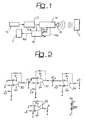
- the reference number 10 designates, as a whole, a chaos generator, preferably of an analog type, which drives a PPM modulator 12.
- the transmission signal (TX) thus obtained is a Chaotic Pulse Position Modulation signal (CPPM) designed to be supplied to a driving block 14 in such a way as to ensure proper operation of a sensor 16.
- CPPM Chaotic Pulse Position Modulation signal
- the sensor 16 may advantageously consist of a normal piezoelectric transducer of the type used, for instance, in burglary-alarm or antitheft systems, such as volumetric and/or antilifting systems used in vehicle applications.
- the transmission signal TX (typically consisting of an ultrasound signal) generated by the sensor 16 illuminates an obstacle O.
- the obstacle O sends the signal that impinges upon it back to the sensor 16 in the form of an echo.
- the sensor 16 detects the said echo signal, generating a receiving signal (RX), which is detected by the driving unit 14 and sent on to a correlator 18.
- the correlator in question receives both the transmission signal TX - on a line 12a- and the received signal RX - on a line 14a -, and is thus able to perform the correlation between the signal transmitted and the echo received by the sensor, in order to obtain the time of flight (TOF) corresponding to the instant at which the function of correlation between the transmitted signal TX and the received echo signal RX reaches its maximum value.
- TOF time of flight
- the reference E generically designates any circuit element that is able to exploit (in a known way and according to the aims of application of the system according to the invention) the signal corresponding to TOF (and hence to the distance between the sensor 16 and the obstacle O) generated by the correlator 18 on an output line designated by 18a.
- the senor 16 preferably consists of an ultrasound sensor, such as an ultrasound sensor manufactured by Polaroid (Series 6500).
- a signal is sent to the sensor 16, the said signal consisting of the alternation of pulse trains generated at two different frequencies (within the useful band of the sensor). Switching between one modulation frequency and the other takes place at time intervals generated according to a chaotic law.
- the generation of the chaotic carrier is entrusted to a so-called Chua's circuit built using operational amplifiers according to the electrical diagram shown in Figure 2.
- the above circuit diagram which comprises four operational amplifiers 20, 22, 24 and 26, corresponds to the solution illustrated in P. Arena, S. Baglio, L. Fortuna, G. Manganaro, "Chua's Circuit Can Be Generated by CNN Cells", IEEE Trans. CAS-1, Feb. 1995, a work to which the reader is referred for a more detailed illustration of said circuit and its modes of operation.
- FIG. 3 illustrates the chaotic attractor called "Chua's double scroll" that may be obtained by means of the circuit of Figure 2.
- Figure 3 reproduces, instead, the possible plot in time of one of the state variables (x 1 ) linked to the aforesaid chaotic attractor.
- the aforesaid state variable x 1 is used as a carrier for driving the PPM modulator 12.
- the reference numbers 28 and 36 designate as many operational amplifiers connected together according to the circuit layout represented in Figure 4. The representation is evident for a person skilled in the sector, and consequently a detailed description is not called for herein. This also applies to the block designated by 38, which consists of a bistable multivibrator.
- the part of circuit comprising the operational amplifier 30 is a saw-tooth generator that is able to generate a ramp with an appropriate slope
- the operational amplifier 34 is basically configured as a threshold comparator in which the aforesaid ramp signal with appropriate slope is compared with the chaotic carrier (state variable X 1 of Figure 3a) applied on an input line 34a.
- the chaotic carrier state variable X 1 of Figure 3a
- the diagram of Figure 4 envisages a circuit implementation in which it is possible to distinguish a block for adaptation of the level of the chaotic signal (elements 28 and 32), an integrator for generation of the ramp (operational amplifier 30 and circuits associated thereto), the comparator of the two signals (operational amplifier 34), and a multivibrator 38 which has the function of adjusting the duration of the pulse.
- the circuit is built in such a way that it is possible to act easily on fundamental parameters, such as the slope of the ramp, the amplification and offset of the chaotic signal, and the duration of the pulse.
- the aim of the foregoing is to adapt the modulated signal to the physical characteristics of the ultrasound sensor 16 according to the modalities which will be described in greater detail hereinafter.
- the senor 16 For the sensor 16 to be able to vary its own oscillation frequency as a result of a variation in the excitation applied it is thus necessary to wait a period of time within which the sensor stabilizes at the new frequency.
- the function of the driving circuit 14 is to generate a signal that is able to drive the ultrasound sensor 16 properly, in such a way that the signal received will not lose the information transmitted, namely the chaotic information.
- the circuit 14 envisages the use of two signals (for instance, square-wave signals) at different frequencies, but in any case comprised within the useful band ⁇ W, transmitted in sequence in such a way that the duration of each of them is equal to the (chaotic) distances generated by the modulator 12.
- the former choice is basically linked to the sensor used, and in particular to the gain curve of the response. Consequently, it is possible to choose any frequencies falling within ⁇ W, even though, in order to render the correlation mechanism more effective it is desirable that the two frequencies should be sufficiently distant from one another.
- the minimum chaotic distance admissible depends upon the time required for the sensor to stabilize on the new frequency whenever a change in frequency occurs.
- the maximum distance is instead determined by the total duration of the signal to be transmitted for detecting the distance and upon the minimum number of samples required for the transmitted signal to be effectively recognized during the correlation stage.
- the corresponding useful band ⁇ W ranges from 50 kHz to 60 kHz with a spatial coverage of between 30 cm and 12 m, and hence with maximum TOF of 100 milliseconds.
- a period of a further 100 milliseconds is required for the sensor 16 to return to the quiescent state.
- the operating frequencies of the sensor are thus chosen at the margins of its band, namely adopting two frequencies F1 and F2 of 50 kHz and 60 kHz, respectively.
- the driving circuit 14 (see Figure 8) use is envisaged of two timer circuits 40, 42 which practically function as oscillators for generating the two frequencies F1, F2 according to the reception of the pulse train coming from the modulator 12.
- the two generators 40, 42 are configured so that at each pulse coming from the modulator 12 they are reset so as to wipe out any regularity present in the signal transmitted.
- the range of the chaotic distances is chosen between a minimum value of 160 microseconds and a maximum value of 200 microseconds.
- the aim of the foregoing is to ensure a minimum of eight oscillations for each of the frequencies F1 and F2 and a minimum of ten chaotic values, there having been imposed a duration of the transmission signal of 2 milliseconds, taking into account the characteristics of the sensor.
- the reference number 44 designates a selection block or electronic switch that transfers onto its own output line 44a either one or the other of the signals coming from the generators 40, 42, according to a switching-control signal generated by a module 46 which is sensitive to the pulses coming from the modulator 12.
- the module 46 acts on the switch 44 in such a way that the latter switches its operating position.
- the frequency of the signal present on the output line 44a switches from F1 to F2 and from F2 to F1 according to an orderly alternating sequence, but with switching instants defined in a chaotic way.
- the reference number 48 designates a third timer designed to generate both a transmission-enable signal (TX enable ), which is forwarded on a line 48a, and a receive-enable signal (INIT), which is forwarded on a line 48b.
- TX enable transmission-enable signal
- IIT receive-enable signal
- the transmission-enable signal TX enable acts on a transmission-control circuit, designated by 50, in such a way as to cause transmission of the signal present on the line 44a (at the frequency F1 or at the frequency F2) to be enabled, for example, for 2 ms every 200 ms.
- the receive-enable signal INIT is transmitted on the line 48b to a receive-enable module, designated by 52.
- the signal INIT is basically a square-wave signal with 50% duty cycle, hence such as to enable reception for 100 ms and to bring the sensor 16 to a quiescent state (in so far as it acts as a receiver) for the remaining 100 ms.
- reference numbers 16a and 16b designate two modules (of a known type) associated to the sensor 16, respectively with the function of a transmission-interface circuit (16a) and with the function of a receiving-interface circuit (16b).
- the transmitted signal TX coming out of the module 50 on a line 50a is sent to the input of the module 16a to enable the corresponding excitation of the sensor 16.
- the above signal is also sent, on a line corresponding to the line 12a of Figure 1, to the correlator 18.
- the receive-enable signal INIT present on the line 52a at output from the module 52 is sent both to the input of the module 16a (to inhibit in any case transmission of the signal TX when the sensor 16 sets itself for listening to the echoes received, namely to the signal RX) and to the input of the correlator 18.
- a further input of said correlator is represented by the line 14a (see also Figure 1), which constitutes the output line of the receiving module 16b.
- FIG. 7 shows that to each burst of the transmitted signal TX there corresponds a first echo RX1 (the echo to be used for the purposes of sensing), which is usually followed by at least one second echo RX2 and further disturbance signals, designated, as a whole, by D.
- the possibility of recognizing the signal received by the ultrasound sensor in a unique way even in the presence of multi-user scenarios and multipath fading is based upon recognition of the strong correlation that said signal maintains with the signal transmitted.
- the above purpose is achieved by using precisely the continuous chaotic modulation (CPPM) of the signal transmitted by the ultrasound.
- CPPM continuous chaotic modulation
- Figure 9 presents the correlation function for a case in which a correct echo (echo I), an echo due to multipath fading (echo II), and a third signal coming from an additional ultrasound sensor (this may be, for instance, a disturbance due to a crosstalk phenomenon) are detected.
Landscapes
- Engineering & Computer Science (AREA)
- Physics & Mathematics (AREA)
- Radar, Positioning & Navigation (AREA)
- Remote Sensing (AREA)
- Computer Networks & Wireless Communication (AREA)
- General Physics & Mathematics (AREA)
- Acoustics & Sound (AREA)
- Measurement Of Velocity Or Position Using Acoustic Or Ultrasonic Waves (AREA)
Abstract
Description
- Figure 1 illustrates, in the form of a block diagram, the general architecture of a system according to the invention;
- Figure 2 is a diagram of a so-called Chua's circuit, which can be used in the framework of the present invention;
- Figure 3 comprises two parts, namely 3a and 3b, which respectively illustrate the chaotic attractor obtained using the circuit of Figure 2, and one of the corresponding state variables, which can be used as a carrier for a pulse position modulation (PPM) modulator;
- Figure 4 illustrates the diagram of said modulator;
- Figures 5 and 6 illustrate the generation of various signals within a system according to the invention, the parts of figures designated by 5b and 6b being zoomed representations of the parts of figures designated by 5a and 6a;
- Figure 7 presents the graphs of the transmission signal and of the echo received in a system according to the invention;
- Figure 8 is a general block diagram of the driving circuit of a sensor used in the framework of the present invention; and
- Figure 9 is a diagram illustrating the result of the correlation between the signal transmitted and the signal received in a system according to the invention.
- the location of the two frequencies within the band ΔW; and
- the range of the time distances generated by the CPPM modulation.
Claims (16)
- A system for detecting the distance from an obstacle (O), comprising at least one transducer (16) for generating a transmission signal (TX) to be sent in the direction of said obstacle (O) and for obtaining a receiving signal (RX) corresponding to an echo produced by the reflection of said transmission signal (TX) off said obstacle (O), characterized in that it comprises a chaos generator (10, 12, 14) for driving said at least one transducer (16) according to a dynamics of chaotic generation, so that said transmission signal (TX) has characteristics of a chaotic signal.
- The system according to Claim 1, characterized in that it comprises a correlator (18) for correlating said transmission signal (TX) and said receiving signal (RX) so as to produce a corresponding correlation signal (18a), so that the distance of said an obstacle (O) from said at least one transducer (16) is identified by the instant at which said correlation function assumes the maximum value.
- The system according to Claim 1 or Claim 2, characterized in that it comprises, as chaos generator (10), a Chua's circuit.
- The system according to any one of Claims 1 to 3, characterized in that said transmission signal (TX) is generated starting from one of the state variables (x1) of said chaos generator (10).
- The system according to any one of the preceding claims, characterized in that it comprises a pulse generator (12) driven by said chaos generator (10) according to a general pulse-position modulation scheme, so that the time interval that elapses between the generation of two consecutive pulses by said pulse generator (12) expresses a chaotic dynamics.
- The system according to Claim 5, characterized in that said pulse generator is a pulse generator of an analog type (12).
- The system according to Claim 6, characterized in that said pulse generator (12) comprises:a ramp-signal source (30); anda threshold comparator in which said ramp signal is compared with a reference signal (34a) produced by a chaos generator, the generation of said pulses occurring when the level of said ramp signal reaches the level of said reference signal of a chaotic type.
- The system according to any one of the preceding claims, characterized in that it comprises a signal source (40 to 46; 50) for producing said transmission signal (TX) with at least one first frequency (F1) and at least one second frequency (F2), different from one another, said signal source (40 to 46; 50) being driven by said chaos generator (10, 12) in such a way that said signal source (40 to 46; 50) modifies the frequency of said transmission signal (TX) according to a chaotic dynamics.
- The system according to Claim 8, characterized in that said signal source (40 to 46; 50) generates said transmission signal (TX) as a square-wave signal of varying frequency.
- The system according to Claim 8 or Claim 9, characterized in that said at least one transducer (16) has a working bandwidth (ΔW), and said signal source (40 to 46; 50) is configured for generating said transmission signal (TX) at frequencies comprised in said working bandwidth (ΔW).
- The system according to Claim 10, characterized in that said signal source (40 to 46; 50) is configured (40, 42) for generating said transmission signal (TX) with a first transmission frequency (F1) and a second transmission frequency (F2), said first transmission frequency (F1) and said second transmission frequency (F2) being located at the ends of said working bandwidth (ΔW) of the transducer.
- The system according to Claim 5 and any one of Claims 8 to 11, characterized in that said signal source (40 to 46; 50) is driven by said pulse generator (12) so that, upon emission of each pulse generated by said pulse generator (12), said signal source (40 to 46; 50) modifies the frequency of said transmission signal (TX).
- The system according to Claim 12, characterized in that said signal source (40 to 46; 50) comprises a plurality of respective signal generators (40, 42), each of which is able to generate a respective signal at a given frequency (F1, F2), and in that said respective signal generators (40, 42) may be reset by said pulse generator (12) upon emission of each of said pulses.
- The system according to any one of the preceding claims, characterized in that said transducer (16) is a piezoelectric transducer.
- The system according to any one of the preceding claims, characterized in that said transducer (16) carries associated to it respective transmission (16a) and receiving (16b) interfaces, so that said transducer (16) may be used both for generating said transmission signal (TX) according to the signal generated by said chaos generator (10) and for obtaining said receiving signal (RX) corresponding to the reflection of said transmission signal (TX) off said obstacle (O).
- The system according to Claim 15, characterized in that it comprises an enabling/disabling circuit (52) for inhibiting simultaneous operation of said transducer (16) both during transmission (16a) and during reception (16b).
Priority Applications (3)
| Application Number | Priority Date | Filing Date | Title |
|---|---|---|---|
| DE60139793T DE60139793D1 (en) | 2001-12-21 | 2001-12-21 | Device for distance measurement by means of chaotic signals |
| EP01830801A EP1324069B1 (en) | 2001-12-21 | 2001-12-21 | A system for detecting distances using chaotic signals |
| US10/325,620 US6738313B2 (en) | 2001-12-21 | 2002-12-20 | System for detecting distances using chaotic signals |
Applications Claiming Priority (1)
| Application Number | Priority Date | Filing Date | Title |
|---|---|---|---|
| EP01830801A EP1324069B1 (en) | 2001-12-21 | 2001-12-21 | A system for detecting distances using chaotic signals |
Publications (2)
| Publication Number | Publication Date |
|---|---|
| EP1324069A1 true EP1324069A1 (en) | 2003-07-02 |
| EP1324069B1 EP1324069B1 (en) | 2009-09-02 |
Family
ID=8184832
Family Applications (1)
| Application Number | Title | Priority Date | Filing Date |
|---|---|---|---|
| EP01830801A Expired - Lifetime EP1324069B1 (en) | 2001-12-21 | 2001-12-21 | A system for detecting distances using chaotic signals |
Country Status (3)
| Country | Link |
|---|---|
| US (1) | US6738313B2 (en) |
| EP (1) | EP1324069B1 (en) |
| DE (1) | DE60139793D1 (en) |
Cited By (4)
| Publication number | Priority date | Publication date | Assignee | Title |
|---|---|---|---|---|
| US6738313B2 (en) * | 2001-12-21 | 2004-05-18 | Stmicroelectronics S.R.L. | System for detecting distances using chaotic signals |
| KR100806860B1 (en) | 2005-05-13 | 2008-02-22 | 삼성전자주식회사 | ??????? system and method thereof |
| CN113820978A (en) * | 2021-09-08 | 2021-12-21 | 华侨大学 | A quasi-synchronous control method for a network teleoperated robot system |
| CN114184682A (en) * | 2021-12-10 | 2022-03-15 | 东莞理工学院 | Dual-chaotic system detection method for weak ultrasonic guided wave signals |
Families Citing this family (16)
| Publication number | Priority date | Publication date | Assignee | Title |
|---|---|---|---|---|
| US7170252B2 (en) * | 2003-07-23 | 2007-01-30 | Renesas Technology Corporation | Location aware automata |
| WO2006073480A2 (en) * | 2004-12-30 | 2006-07-13 | The National Research Exchange, Inc. | Dispute resolution method and system |
| KR100758271B1 (en) * | 2005-12-08 | 2007-09-12 | 한국전자통신연구원 | Apparatus and method for ranging measurement using chaotic UWB wireless communication |
| KR100730086B1 (en) * | 2006-07-10 | 2007-06-19 | 삼성전기주식회사 | Dual system transceiver |
| KR101079405B1 (en) * | 2008-12-08 | 2011-11-02 | 한밭대학교 산학협력단 | Parallel sequence spread spectrum type chaotic signal transmitter |
| WO2012123787A1 (en) * | 2011-03-14 | 2012-09-20 | Nokia Corporation | An echolocation apparatus |
| DE102011075484A1 (en) | 2011-05-09 | 2012-11-15 | Robert Bosch Gmbh | Minimized range ultrasound measuring system and method for detecting an obstacle |
| DE102011102202A1 (en) * | 2011-05-21 | 2012-11-22 | Volkswagen Aktiengesellschaft | Environment detection device in a motor vehicle and method for environment detection using a correlation |
| DE102012215858B4 (en) * | 2012-09-06 | 2020-07-30 | Fraunhofer-Gesellschaft zur Förderung der angewandten Forschung e.V. | EVALUATION DEVICE FOR A SYSTEM FOR OBJECT DETECTION |
| DE102014202864A1 (en) * | 2014-02-17 | 2015-08-20 | Robert Bosch Gmbh | Device for echo-based environment sensors |
| US9651458B2 (en) * | 2014-09-19 | 2017-05-16 | Swisslog Logistics Inc. | Method and system for auto safety verification of AGV sensors |
| EP3497477B1 (en) | 2016-08-12 | 2026-03-11 | Fastree3D SA | Method and device for measuring a distance to a target in a multi-user environment by means of at least one detector |
| CN107888372B (en) * | 2017-12-19 | 2024-03-15 | 北京富迪广通科技发展有限公司 | Underwater sonar communication system based on chaotic oscillator array element |
| CN110138363A (en) * | 2019-04-12 | 2019-08-16 | 齐鲁理工学院 | An analog circuit for a three-dimensional integer-order FM system |
| US12358170B2 (en) | 2021-03-01 | 2025-07-15 | Samsung Electronics Co., Ltd. | Method and apparatus for robot collision avoidance by full surface proximity detection |
| CN113567974B (en) * | 2021-06-22 | 2023-11-03 | 太原理工大学 | Multi-living-body intelligent detection device and method based on CPPWM radar |
Citations (2)
| Publication number | Priority date | Publication date | Assignee | Title |
|---|---|---|---|---|
| GB2156986A (en) * | 1984-03-31 | 1985-10-16 | Licentia Gmbh | Determining distance ultrasonically |
| US5321409A (en) * | 1993-06-28 | 1994-06-14 | Hughes Missile Systems Company | Radar system utilizing chaotic coding |
Family Cites Families (3)
| Publication number | Priority date | Publication date | Assignee | Title |
|---|---|---|---|---|
| CN1335516A (en) * | 2000-07-25 | 2002-02-13 | 北京闻亭科技发展有限责任公司 | Method of using high speed chaotic code as phase modulating signal source of radar |
| DE10108584A1 (en) * | 2001-02-22 | 2002-09-05 | Bosch Gmbh Robert | Method for interference suppression of a radar device and radar device |
| DE60139793D1 (en) * | 2001-12-21 | 2009-10-15 | St Microelectronics Srl | Device for distance measurement by means of chaotic signals |
-
2001
- 2001-12-21 DE DE60139793T patent/DE60139793D1/en not_active Expired - Lifetime
- 2001-12-21 EP EP01830801A patent/EP1324069B1/en not_active Expired - Lifetime
-
2002
- 2002-12-20 US US10/325,620 patent/US6738313B2/en not_active Expired - Lifetime
Patent Citations (2)
| Publication number | Priority date | Publication date | Assignee | Title |
|---|---|---|---|---|
| GB2156986A (en) * | 1984-03-31 | 1985-10-16 | Licentia Gmbh | Determining distance ultrasonically |
| US5321409A (en) * | 1993-06-28 | 1994-06-14 | Hughes Missile Systems Company | Radar system utilizing chaotic coding |
Non-Patent Citations (9)
| Title |
|---|
| ARENA P ET AL: "CHUA'S CIRCUIT CAN BE GENERATED BY CNN CELLS", IEEE TRANSACTIONS ON CIRCUITS AND SYSTEMS I: FUNDAMENTAL THEORY AND APPLICATIONS, IEEE INC. NEW YORK, US, vol. 42, no. 2, 1 February 1995 (1995-02-01), pages 122 - 125, XP000510186, ISSN: 1057-7122 * |
| EVERETT H R: "SURVEY OF COLLISION AVOIDANCE AND RANGING SENSORS FOR MOBILE ROBOTS", ROBOTICS AND AUTONOMOUS SYSTEMS, ELSEVIER SCIENCE PUBLISHERS, AMSTERDAM, NL, vol. 58, no. 1, 1 May 1989 (1989-05-01), pages 5 - 67, XP000113868, ISSN: 0921-8890 * |
| FORTUNA L ET AL: "Chaos preservation through continuous chaotic pulse position modulation", ISCAS 2001. THE 2001 IEEE INTERNATIONAL SYMPOSIUM ON CIRCUITS AND SYSTEMS (CAT. NO.01CH37196), ISCAS 2001. THE 2001 IEEE INTERNATIONAL SYMPOSIUM ON CIRCUITS AND SYSTEMS, SYDNEY, NSW, AUSTRALIA, 6-9 MAY 2001, 2001, Piscataway, NJ, USA, IEEE, USA, pages 803 - 806 vol. 2, XP002199708, ISBN: 0-7803-6685-9 * |
| H.R. EVERETT: "Sensors for Mobile Robots, Theory and Application", 1995, A.K. PETERS LTD. |
| KAWABATA K ET AL.: "Distance measurement method under multiple ultra sonic sensors environment", INDUSTRIAL ELECTRONICS, CONTROL, AND , INSTRUMENTATION, 5 August 1996 (1996-08-05), pages 812 - 816 |
| KAWABATA K ET AL: "Distance measurement method under multiple ultra sonic sensors environment", INDUSTRIAL ELECTRONICS, CONTROL, AND INSTRUMENTATION, 1996., PROCEEDINGS OF THE 1996 IEEE IECON 22ND INTERNATIONAL CONFERENCE ON TAIPEI, TAIWAN 5-10 AUG. 1996, NEW YORK, NY, USA,IEEE, US, 5 August 1996 (1996-08-05), pages 812 - 816, XP010203479, ISBN: 0-7803-2775-6 * |
| KOLUMBAN G ET AL: "THE ROLE OF SYNCHRONIZATION IN DIGITAL COMMUNICATIONS USING CHAOS -PART I: FUNDAMENTALS OF DIGITAL COMMUNICATIONS", IEEE TRANSACTIONS ON CIRCUITS AND SYSTEMS I: FUNDAMENTAL THEORY AND APPLICATIONS, IEEE INC. NEW YORK, US, vol. 44, no. 10, 1 October 1997 (1997-10-01), pages 927 - 936, XP000722574, ISSN: 1057-7122 * |
| KOLUMBAN G ET AL: "THE ROLE OF SYNCHRONIZATION IN DIGITAL COMMUNICATIONS USING CHAOS -PART II: CHAOTIC MODULATION AND CHAOTIC SYNCHRONIZATION", IEEE TRANSACTIONS ON CIRCUITS AND SYSTEMS I: FUNDAMENTAL THEORY AND APPLICATIONS, IEEE INC. NEW YORK, US, vol. 45, no. 11, November 1998 (1998-11-01), pages 1129 - 1139, XP000866877, ISSN: 1057-7122 * |
| KOLUMBAN GEZA ET AL: "Role of synchronization in digital communications using chaos - Part III: Performance bounds for correlation receivers", IEEE TRANS CIRCUITS SYST I FUNDAM THEOR APPL;IEEE TRANSACTIONS ON CIRCUITS AND SYSTEMS I: FUNDAMENTAL THEORY AND APPLICATIONS DEC 2000 IEEE, PISCATAWAY, NJ, USA, vol. 47, no. 12, December 2000 (2000-12-01), pages 1673 - 1683, XP002199709 * |
Cited By (5)
| Publication number | Priority date | Publication date | Assignee | Title |
|---|---|---|---|---|
| US6738313B2 (en) * | 2001-12-21 | 2004-05-18 | Stmicroelectronics S.R.L. | System for detecting distances using chaotic signals |
| KR100806860B1 (en) | 2005-05-13 | 2008-02-22 | 삼성전자주식회사 | ??????? system and method thereof |
| CN113820978A (en) * | 2021-09-08 | 2021-12-21 | 华侨大学 | A quasi-synchronous control method for a network teleoperated robot system |
| CN114184682A (en) * | 2021-12-10 | 2022-03-15 | 东莞理工学院 | Dual-chaotic system detection method for weak ultrasonic guided wave signals |
| CN114184682B (en) * | 2021-12-10 | 2024-04-30 | 东莞理工学院 | Dual Chaotic System Detection Method for Weak Ultrasonic Guided Wave Signals |
Also Published As
| Publication number | Publication date |
|---|---|
| EP1324069B1 (en) | 2009-09-02 |
| US6738313B2 (en) | 2004-05-18 |
| DE60139793D1 (en) | 2009-10-15 |
| US20030133362A1 (en) | 2003-07-17 |
Similar Documents
| Publication | Publication Date | Title |
|---|---|---|
| EP1324069B1 (en) | A system for detecting distances using chaotic signals | |
| Fortuna et al. | Chaotic pulse position modulation to improve the efficiency of sonar sensors | |
| JP7382107B2 (en) | Time-of-flight and code signature detection for coded ultrasound transmissions | |
| RU2158936C2 (en) | Identification mark operating with surface acoustic waves | |
| EP0718637B1 (en) | Radar system | |
| CN106415311B (en) | method for detecting target echo, ultrasonic sensor device and motor vehicle | |
| US20070241955A1 (en) | System Having Two or More Sensors | |
| EP0102074A2 (en) | Method and apparatus for detecting position of object with ultrasonic wave | |
| EP2263100A2 (en) | Method and apparatus for communication in ultra-wide bandwidth rfid systems | |
| Sabatini et al. | A low-cost, composite sensor array combining ultrasonic and infrared proximity sensors | |
| US20110116345A1 (en) | Position detection system, transmission device, reception device, position detection method and position detection program | |
| US20200072973A1 (en) | Method for operating an ultrasonic sensor | |
| US4682173A (en) | Radar responder | |
| CN105180982B (en) | Saw delay reflection-type wireless sensor system with anti-collision | |
| US12000969B2 (en) | Vehicle collision determination apparatus | |
| US12352854B2 (en) | Object detection device | |
| JP3141278B2 (en) | Ultrasonic sensor | |
| Wirnitzer et al. | Interference cancelation in ultrasonic sensor arrays by stochastic coding and adaptive filtering | |
| JP2000266849A (en) | Distance detection device | |
| US12379475B2 (en) | Ultrasonic sensor control device, ultrasonic sensor, and ultrasonic sensor control method | |
| US11899106B1 (en) | Dual-channel acoustic distance measurement circuit and method | |
| JP2648605B2 (en) | Underwater detector | |
| US12174294B2 (en) | Method and apparatus for detecting object | |
| US20250291043A1 (en) | Sonar apparatus and object detection method | |
| JP2005318553A (en) | Position detection system, response device, position detection method, position detection program and information recording medium |
Legal Events
| Date | Code | Title | Description |
|---|---|---|---|
| PUAI | Public reference made under article 153(3) epc to a published international application that has entered the european phase |
Free format text: ORIGINAL CODE: 0009012 |
|
| AK | Designated contracting states |
Designated state(s): AT BE CH CY DE DK ES FI FR GB GR IE IT LI LU MC NL PT SE TR |
|
| AX | Request for extension of the european patent |
Extension state: AL LT LV MK RO SI |
|
| 17P | Request for examination filed |
Effective date: 20030813 |
|
| AKX | Designation fees paid |
Designated state(s): DE FR GB IT |
|
| 17Q | First examination report despatched |
Effective date: 20080229 |
|
| GRAP | Despatch of communication of intention to grant a patent |
Free format text: ORIGINAL CODE: EPIDOSNIGR1 |
|
| GRAS | Grant fee paid |
Free format text: ORIGINAL CODE: EPIDOSNIGR3 |
|
| GRAA | (expected) grant |
Free format text: ORIGINAL CODE: 0009210 |
|
| RIN1 | Information on inventor provided before grant (corrected) |
Inventor name: BARTOLONE, MARCO Inventor name: FRASCA, MATTIA Inventor name: RIZZO, ALESSANDRO Inventor name: FORTUNA, LUIGI Inventor name: BRANCIFORTE, MARCO |
|
| AK | Designated contracting states |
Kind code of ref document: B1 Designated state(s): DE FR GB IT |
|
| REF | Corresponds to: |
Ref document number: 60139793 Country of ref document: DE Date of ref document: 20091015 Kind code of ref document: P |
|
| RAP2 | Party data changed (patent owner data changed or rights of a patent transferred) |
Owner name: STMICROELECTRONICS SRL |
|
| PLBE | No opposition filed within time limit |
Free format text: ORIGINAL CODE: 0009261 |
|
| STAA | Information on the status of an ep patent application or granted ep patent |
Free format text: STATUS: NO OPPOSITION FILED WITHIN TIME LIMIT |
|
| 26N | No opposition filed |
Effective date: 20100603 |
|
| GBPC | Gb: european patent ceased through non-payment of renewal fee |
Effective date: 20091221 |
|
| REG | Reference to a national code |
Ref country code: FR Ref legal event code: ST Effective date: 20100831 |
|
| PG25 | Lapsed in a contracting state [announced via postgrant information from national office to epo] |
Ref country code: FR Free format text: LAPSE BECAUSE OF NON-PAYMENT OF DUE FEES Effective date: 20091231 |
|
| PG25 | Lapsed in a contracting state [announced via postgrant information from national office to epo] |
Ref country code: GB Free format text: LAPSE BECAUSE OF NON-PAYMENT OF DUE FEES Effective date: 20091221 |
|
| PGFP | Annual fee paid to national office [announced via postgrant information from national office to epo] |
Ref country code: IT Payment date: 20101127 Year of fee payment: 10 |
|
| PGFP | Annual fee paid to national office [announced via postgrant information from national office to epo] |
Ref country code: DE Payment date: 20101208 Year of fee payment: 10 |
|
| REG | Reference to a national code |
Ref country code: DE Ref legal event code: R119 Ref document number: 60139793 Country of ref document: DE Effective date: 20130702 |
|
| PG25 | Lapsed in a contracting state [announced via postgrant information from national office to epo] |
Ref country code: DE Free format text: LAPSE BECAUSE OF NON-PAYMENT OF DUE FEES Effective date: 20130702 |
|
| PG25 | Lapsed in a contracting state [announced via postgrant information from national office to epo] |
Ref country code: IT Free format text: LAPSE BECAUSE OF NON-PAYMENT OF DUE FEES Effective date: 20121221 |