EP1324029A2 - Fluorescent transilluminator - Google Patents
Fluorescent transilluminator Download PDFInfo
- Publication number
- EP1324029A2 EP1324029A2 EP02090425A EP02090425A EP1324029A2 EP 1324029 A2 EP1324029 A2 EP 1324029A2 EP 02090425 A EP02090425 A EP 02090425A EP 02090425 A EP02090425 A EP 02090425A EP 1324029 A2 EP1324029 A2 EP 1324029A2
- Authority
- EP
- European Patent Office
- Prior art keywords
- fluorescent
- ultraviolet
- source
- transilluminator
- ultraviolet source
- Prior art date
- Legal status (The legal status is an assumption and is not a legal conclusion. Google has not performed a legal analysis and makes no representation as to the accuracy of the status listed.)
- Withdrawn
Links
Images



Classifications
-
- G—PHYSICS
- G01—MEASURING; TESTING
- G01N—INVESTIGATING OR ANALYSING MATERIALS BY DETERMINING THEIR CHEMICAL OR PHYSICAL PROPERTIES
- G01N21/00—Investigating or analysing materials by the use of optical means, i.e. using sub-millimetre waves, infrared, visible or ultraviolet light
- G01N21/62—Systems in which the material investigated is excited whereby it emits light or causes a change in wavelength of the incident light
- G01N21/63—Systems in which the material investigated is excited whereby it emits light or causes a change in wavelength of the incident light optically excited
- G01N21/64—Fluorescence; Phosphorescence
-
- G—PHYSICS
- G01—MEASURING; TESTING
- G01N—INVESTIGATING OR ANALYSING MATERIALS BY DETERMINING THEIR CHEMICAL OR PHYSICAL PROPERTIES
- G01N21/00—Investigating or analysing materials by the use of optical means, i.e. using sub-millimetre waves, infrared, visible or ultraviolet light
- G01N21/17—Systems in which incident light is modified in accordance with the properties of the material investigated
- G01N21/25—Colour; Spectral properties, i.e. comparison of effect of material on the light at two or more different wavelengths or wavelength bands
- G01N21/31—Investigating relative effect of material at wavelengths characteristic of specific elements or molecules, e.g. atomic absorption spectrometry
- G01N21/33—Investigating relative effect of material at wavelengths characteristic of specific elements or molecules, e.g. atomic absorption spectrometry using ultraviolet light
-
- G—PHYSICS
- G01—MEASURING; TESTING
- G01N—INVESTIGATING OR ANALYSING MATERIALS BY DETERMINING THEIR CHEMICAL OR PHYSICAL PROPERTIES
- G01N27/00—Investigating or analysing materials by the use of electric, electrochemical, or magnetic means
- G01N27/26—Investigating or analysing materials by the use of electric, electrochemical, or magnetic means by investigating electrochemical variables; by using electrolysis or electrophoresis
- G01N27/416—Systems
- G01N27/447—Systems using electrophoresis
- G01N27/44704—Details; Accessories
- G01N27/44717—Arrangements for investigating the separated zones, e.g. localising zones
- G01N27/44721—Arrangements for investigating the separated zones, e.g. localising zones by optical means
-
- G—PHYSICS
- G01—MEASURING; TESTING
- G01N—INVESTIGATING OR ANALYSING MATERIALS BY DETERMINING THEIR CHEMICAL OR PHYSICAL PROPERTIES
- G01N2201/00—Features of devices classified in G01N21/00
- G01N2201/06—Illumination; Optics
- G01N2201/061—Sources
Definitions
- the present invention relates to a fluorescent transilluminator for exposing an object to be irradiated to ultraviolet rays to make it fluoresce.
- a DNA analysis system uses gel electrophoresis as one of the remarkably effective techniques for analyzing nucleic acids or proteins.
- gel electrophoresis an electric field is applied to a gel containing an electrolyte. Then, charged particles move in the gel. In this event, differences among the charged particles in size, shape, charge, and so on cause differences among respective moving rates of charged particles. Using the differences among the moving rates allows separating molecules of the nucleic acids, the proteins, or the like.
- the nucleic acids separated by electrophoresis as described above are not visible, when they are left as they are, so, in order to observe the nucleic acid separated, the gel is stained with a solution of fluorescent substance (e.g., ethidium bromide) bindable to the nucleic acid.
- a fluorescent substance such as ethidium bromide is previously added in preparing the gel. If the gel stained with fluorescent substance in this way is exposed to ultraviolet rays, portions corresponding to the nucleic acid fluoresce in orange. This allows observation of the nucleic acids.
- subjecting a marker, of which the molecular weight has been known, to electrophoresis together with a sample allows measurement of the molecular weight of the sample.
- An ultraviolet lamp unit used for irradiating ultraviolet rays as described above is collectively named "fluorescent transilluminator”.
- a fluorescent transilluminator similar to this has been also disclosed in USP 5347342 and others.
- a top window (opening) is formed on the case containing an ultraviolet source.
- the top window has a structure in which a visible light-cutting filter (ultraviolet band filter) is installed and the sample is put above the visible light-cutting filter. Through this structure, ultraviolet rays emitted from the ultraviolet source are transmitted through the top window having the visible light-cutting filter and irradiated to the sample.
- UV ultraviolet rays
- the first class comprises ultraviolet rays with wavelengths ranging from about 315 nm to 400 nm, which are called UV-A and also called near ultraviolet rays. These near ultraviolet rays have a pigmentation (so-called sunburn) function.
- the second one comprises ultraviolet rays with wavelengths ranging from about 280 nm to 315 nm, which are called UV-B.
- the ultraviolet rays with these wavelengths cause erythema (irritating the skin). It is also said that such ultraviolet rays are necessary for biosynthesis of vitamin D.
- the third one comprises ultraviolet rays with wavelengths ranging from 100 nm to 280 nm, which are called UV-C.
- ultraviolet rays also called disinfecting rays have a literally disinfecting function.
- the fluorescent transilluminator since ultraviolet rays in the UV-B band can effectively make a fluorescent substance (ethidium bromide) fluoresce, the light source that emits ultraviolet rays of the UV-B band is adopted.
- a mercury fluorescent lamp which is assembled with a fluorescent body such as ((Ca, Zn) 3 (PO 4 ) 2 :Tl) having an emission peak within a UV-B wavelength band ranging from about 280 to 315 nm, is used.
- the light source of the fluorescent transilluminator used currently is a mercury-based light source lamp, in which mercury is sealed, such as an ultraviolet fluorescent lamp or a mercury lamp having a mercury line spectrum as its excitation source.
- mercury such as an ultraviolet fluorescent lamp or a mercury lamp having a mercury line spectrum as its excitation source.
- the mercury vapor pressure reduces and the start of discharge becomes difficult.
- vapor pressure of sealed mercury rises in accordance with temperature increase after lighting of the lamp, emission strength thereby varies from immediately after the lamp is started until a condition becomes stable, and thus a long time is required to stabilize the light output.
- the mercury-based light source lamp conventionally used has a disadvantage of requiring a long start-up time particularly in cold districts and in the winter season.
- the mercury fluorescent lamp is used for an analysis of nucleic acids and proteins such as the abovementioned, because of the long required time to stabilize the light output and start the analysis, the problem may arise that before start of the analysis, a sample, particularly a delicate sample such as a DNA sample, is damaged.
- light emitted from the conventional mercury fluorescent lamp contains visible light components and hence, in the case where such a mercury fluorescent lamp is used as the light source, in order to assure that the visible light components do not adversely affect an observation, it becomes essential to use the visible light-cutting filter for transmitting ultraviolet rays and cutting the visible light.
- this filter is a peculiar filter and very expensive due to its specialty so that it costs 30 to 80 percent of the commercial price of a fluorescent transilluminator product.
- the mercury fluorescent lamp as the conventional light source of the fluorescent transilluminator provides such a weak emission strength that it may not make the sample for observation fluoresce sufficiently.
- the fluorescent transilluminator according to the present invention has a light source emitting only ultraviolet rays with a sharp emission spectrum, particularly, the emission spectrum having a peak emission wavelength at 313 nm with 5 nm or shorter half width. Therefore, the fluorescent transilluminator can be adapted to irradiate an object with ultraviolet rays emitted by the ultraviolet source without cutting of visible light but only through a space and/ or a member transmitting light having wave lengths equal to or longer than 300 nm, ranging from the ultraviolet region to the visible light region and this allows the transilluminator to assure that no disturbance occurs in the observation such as in gel electrophoresis. Consequently, a costly visible light-cutting filter is no longer required.
- the ultraviolet source which can emit such a sharp emission spectrum, can be formed by using a gadolinium-activated fluorescent body. Wherein, for an excitation source for exciting the fluorescent body to make it fluoresce, using xenon discharge is advantageously used. Utilization of such an excitation source allows the ultraviolet source to be of an excellent start-up characteristic almost suffering no influence of an ambient temperature in contrast to the conventional mercury fluorescent lamp. Moreover, the ultraviolet source can emit an emission of stronger intensity than that of the conventional mercury fluorescent lamp.
- a transmission window formed of a glass plate can be installed, which can transmit light with wavelengths equal to or longer than 300 nm, ranging from the ultraviolet region to the visible light region, instead of that formed of a visible light-cutting filter in prior art. Installing such a transmission window allows mounting an object to be irradiated above this transmission window to irradiate advantageously the object.
- the ultraviolet source can be, particularly, formed in a flat plate. Through this constitution, ultraviolet rays are emitted from one surface of the ultraviolet source and so it is easy to prevent exposure of an unnecessary site to ultraviolet rays. Moreover, forming a portion of the outer surface of the fluorescent transilluminator with a member constructing an emission surface of the ultraviolet source allows arranging the object to be irradiated directly on the member to raise irradiation efficiency of the object.
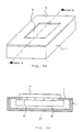
- fluorescent transilluminator 60 has plate-like ultraviolet source 10 and case 1 housing it. Transmission window 61 is formed as an opening in top plate 6 of case 1.
- an ultraviolet transmission filter (a visible light-cutting filter) should be installed in the portion corresponding to transmission window 61.
- fluorescent transilluminator 60 has, as illustrated herein, a novel constitution in which there is only the opening as transmission window 61 and no expensive filter is required. As described later, such a constitution becomes possible by using fluorescent transilluminator 60 that emits only ultraviolet rays with a sharp emission spectrum.
- Fluorescent transilluminator 60 can be preferably applied for an analysis using gel electrophoresis.
- electrophoretically treated gel 4 stained with fluorescent substance is mounted above transmission window 61 as an object to be irradiated.
- the size of transmission window 61 is made smaller than that of electrophoretically treated gel 4 and electrophoretically treated gel 4 is mounted on an edge of transmission window 61.
- Ultraviolet rays emitted from ultraviolet source 10 pass through transmission window 61 to irradiate electrophoretically treated gel 4.
- illustration of electrophoretically treated gel 4 is omitted.
- the size of transmission window 61 can be larger than that of electrophoretically treated gel 4 and even in this case, electrophoretically treated gel 4 can be arranged above transmission window 61 through improving a method for mounting electrophoretically treated gel 4.
- the top surface plate of plate-like ultraviolet source 10 is in close contact with the bottom surface of the edge of transmission window 61; in this case, a sample such as electrophoretically treated gel 4 having a smaller size than that of transmission window 61 can be directly mounted on the top face plate of ultraviolet source 10.
- the size of transmission window 61 coincides with that of the top face plate of ultraviolet source 10 and the top surface of top plate 6 lies with that of the top face plate of ultraviolet source 10 in a common plane.
- a plate member such as a quartz glass plate transmitting light with wavelengths ranging from the ultraviolet band to visible light band, in other words, wavelengths of 300 nm or longer may be installed in transmission window 61.
- a plate member can be fabricated at a low cost; and thus the advantage of the present invention that a low fabrication cost is realized, is not lost even if this plate member is used.
- the ultraviolet source emitting only ultraviolet rays with the sharp emission spectrum having a peak emission wavelength at 313 nm with 5 nm or shorter half width
- an optical glass plate such as a cheap borosilicate glass, which passes light with wavelengths equal to or longer than 300 nm, ranging from the ultraviolet region to the visible light region, as the plate member fitted in transmission window 61.
- Adopting borosilicate glass plate allows fabricating a fluorescent transilluminator of strong market competitiveness and a high commercial value due to its low price.
- plate-like ultraviolet source 10 The constitution of plate-like ultraviolet source 10 will be described below with reference to Fig. 3a and Fig. 3b.
- Ultraviolet source 10 has electrode substrate 11 consisting of a plate-like soda glass. On electrode substrate 11, as shown in Fig. 3b, finger-like electrode patterns 12 and 14 are formed through applying a conductive paste consisting of silver or copper, for example, used as an electrode material by screenprinting method.
- dielectric material layer 15 is formed, which is comprised of a dielectric material mainly consisting of silica, wherein, on the uppermost layer of dielectric material layer 15, a layer consisting of a secondary electron-emitting material such as magnesium oxide, which also serves as a protecting film, and/or an ultraviolet-emitting fluorescent body may be formed.
- opposite substrate 21 is arranged facing to the surface of electrode substrate 11 on the side of electrode patterns 12 and 14. The rays are emitted in the direction toward opposite substrate 21.
- an ultraviolet rays permeable glass such as an optical glass can be used and ultraviolet fluorescent body layer 22 ranging from 20 to 50 ⁇ m in thickness is printed on the surface thereof facing to electrode substrate 11.
- glass frame 23 is installed as a spacer for locating these two members in parallel to each other to secure a prescribed discharge space.
- Glass frame 23 is attached to electrode substrate 11 and opposite substrate 21 by fusion bonding. In this way, the inside of the discharge space surrounded by these members is hermetically sealed.
- a member other than the glass frame may be used if it can hermetically seal the space.
- the discharge space formed in this way is evacuated and instead a rare gas is sealed in the discharge space.
- a rare gas is sealed in the discharge space.
- a xenon (Xe) gas, a mixture gas consisting of Xe and argon (AR), or a mixture gas consisting of Xe, Ar, and neon (Ne) can be used.
- Ultraviolet source 10 can emit through application of a sinusoid wave or a pulse wave of several 10 kHz frequencies between electrode patterns 12 and 14. In other words, application of a voltage between electrode patterns 12 and 14 causes the xenon gas to discharge and emit vacuum ultraviolet radiation. This vacuum ultraviolet radiation is absorbed by fluorescent body layer 22 and then, fluorescent body layer 22 emits ultraviolet rays.
- a fluorescent body activated by gadolinium (Gd) is used to form ultraviolet fluorescent body layer 22 instead of the ultraviolet fluorescent body such as (Ca, Zn) 3 (PO 4 ) 2 :Tl which has been conventionally used.
- the ultraviolet fluorescent body activated by gadolinium used for the present embodiment particularly, an YB x O y :Gd fluorescent body (x and y are arbitrary positive integer) such as YBO 3 :Gd fluorescent body is preferably used.
- YB x O y :Gd fluorescent body x and y are arbitrary positive integer
- YBO 3 :Gd fluorescent body is preferably used.
- Preferable examples of various specific compositions will be described later.
- an emission with a sharp line spectrum can be generated in contrast with a conventional thalium (Tl)-activated fluorescent body.
- the emission wavelengths of ultraviolet source 10 are in the UV-B band ranging from 280 nm to 315 nm.
- the inventor found that, by the use of ultraviolet source 10 irradiating ultraviolet rays of such a sharp line spectrum, not only effective fluorescent luminescence of a pigment for light emission of a DNA, e.g., ethidium bromide, but also observation of the necessary fluorescence only from the DNA, the other extra light being nearly excluded, could be realized.
- a light source containing no mercury is adopted as ultraviolet source 10.
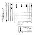
- the difference between start-up states of the existing mercury fluorescent lamp and this ultraviolet source 10 will be described as follows with reference to Fig. 5.
- Fig. 5 shows that time of about 50 seconds is required until the light output has become stable in the conventional mercury fluorescent lamp. In other words, at least 50 seconds is required for the mercury vapor in a tube to become stable.
- problems may arise in that an adverse effect occurs in the sample, such as that the DNA as the object of observation is damaged before emission becomes stable.
- the start-up characteristic of the fluorescent lamp tends to further deteriorate in a low temperature atmosphere.
- ultraviolet source 10 used in fluorescent transilluminator 60 according to the embodiment can reach the stable emission state rapidly compared with the conventional one, that is, immediately after it is turned on, it can yield a 100% light output. Hence, damage of a sample such as the DNA before observation can be reduced.
- the start-up characteristic of ultraviolet source 10 is not generally influenced by an atmospheric temperature and thus, ultraviolet source 10 is suitable particularly for use in cold districts and in winter season.
- ultraviolet source 10 in the present embodiment has excellent characteristics, that is, emission of only ultraviolet rays with a sharp line spectrum, rapid start-up, almost no effect from the atmospheric temperature, and stronger emission than the conventional mercury fluorescent lamp are acquired.
- the visible light-cutting filter which is expensive and necessary in prior art, becomes unnecessary and product cost is, therefore, reduced, the adverse effect on a delicate sample can be reduced, and the sample can be effectively fluoresced to present a good analysis.
- An advantageous light source for use as the ultraviolet source of the fluorescent transilluminator in this way is not restricted to those as described above, but any one having a constitution, in which vacuum ultraviolet radiation generated by xenon discharge is absorbed by the fluorescent body activated by Gd to emit ultraviolet rays, may be used.
- the ultraviolet source can be actuated by the sinusoidal wave and the pulse wave, namely, use of a DC inverter and, therefore, electrical power consumption can be saved. Moreover, since consumables such as a cathode and a filament are not used, the ultraviolet source has an advantage of having a long. life.
- the ultraviolet source may have the constitution, as described in the present embodiment, of flat plate-like shape and emitting the light from one surface thereof. This constitution allows a reduction of the amount of ultraviolet rays incident on an unnecessary portion to result in the decreasing of deterioration of tools caused by ultraviolet rays.
- the ultraviolet source can be formed in a tube shape. In the latter case, a tubular member forming a discharge space is formed with a material such as glass passing UV-B ultraviolet rays.
Landscapes
- Health & Medical Sciences (AREA)
- Physics & Mathematics (AREA)
- Life Sciences & Earth Sciences (AREA)
- Chemical & Material Sciences (AREA)
- General Physics & Mathematics (AREA)
- Pathology (AREA)
- Biochemistry (AREA)
- General Health & Medical Sciences (AREA)
- Analytical Chemistry (AREA)
- Immunology (AREA)
- Spectroscopy & Molecular Physics (AREA)
- Molecular Biology (AREA)
- Chemical Kinetics & Catalysis (AREA)
- Electrochemistry (AREA)
- Nuclear Medicine, Radiotherapy & Molecular Imaging (AREA)
- Investigating, Analyzing Materials By Fluorescence Or Luminescence (AREA)
- Vessels And Coating Films For Discharge Lamps (AREA)
- Investigating Or Analysing Materials By Optical Means (AREA)
Abstract
Description
the
| No. | Composition | Emission strength | No. | Composition | Emission strength |
| 1 | YBO3:Gd | 9.0 | 8 | LaP3O9:Gd | 8.4 |
| 2 | YB2O5:Gd | 9.5 | 9 | SrB4O7:Gd | 8.3 |
| 3 | NaGdSiO4 | 8.3 | 10 | LaPO4:Gd | 8.2 |
| 4 | YAl3(BO3)4:Gd | 8.1 | 11 | LaNgB5O10:Gd,Pr | 9.7 |
| 5 | LaBO3:Gd | 8.2 | 12 | LaB3O8:Gd,Pr | 9.8 |
| 6 | YPO4:Gd | 8.6 | 13 | (Ca,Zn)3(PO4)2:Tl (Conventional) | 8.0 |
| 7 | YAlO3:Gd | 8.3 |
Claims (10)
- A fluorescent transilluminator housing an ultraviolet source and emitting ultraviolet rays from said ultraviolet source to an outside object to be irradiated, wherein
said ultraviolet source emits only ultraviolet rays having a sharp line spectrum and the ultraviolet rays from said ultraviolet source is irradiated to said object through a space and/ or a member transmitting light with wavelengths equal to or longer than 300 nm ranging from the ultraviolet region to the visible light region. - A fluorescent transilluminator according to claim 1, wherein said ultraviolet source emits a spectrum having a peak emission wavelength at 313 nm with 5 nm or shorter half width.
- A fluorescent transilluminator according to claim 1, wherein said ultraviolet source has a fluorescent body emitting ultraviolet rays and an excitation source exciting said fluorescent body to make it fluoresce, said fluorescent body being activated by gadolinium.
- A fluorescent transilluminator according to claim 1, wherein said ultraviolet source has a fluorescent body emitting ultraviolet rays and an excitation source exciting said fluorescent body to make it fluoresce, and said excitation source uses xenon discharge.
- A fluorescent transilluminator according to claim 1, wherein a transmission window, which is formed of a glass plate transmitting light with wavelengths equal to or longer than 300 nm ranging from the ultraviolet region to the visible light region, is installed between said ultraviolet source and said object to be irradiated.
- A fluorescent transilluminator according to claim 1, wherein said object to be irradiated is an electrophoretically treated gel stained with fluorescent substance.
- A fluorescent transilluminator according to claim 1, wherein said ultraviolet source has a flat plate-like external shape.
- A fluorescent transilluminator according to claim 7, wherein a member constructing an emission surface of said ultraviolet source forms a portion of an outer surface of said fluorescent transilluminator.
- A fluorescent transilluminator, which irradiates an electrophoretically treated gel stained with fluorescent substance with ultraviolet rays having a wavelengths ranging from 280 to 315 nm, wherein a transmission window, which passes light of wavelengths equal to or longer than 300 nm ranging from the ultraviolet region to the visible light region, is installed between the ultraviolet source housed in the fluorescent transilluminator and said electrophoretically treated gel.
- A fluorescent transilluminator housing an ultraviolet source and emitting ultraviolet rays from said ultraviolet source to an outside object to be irradiated, wherein
said ultraviolet source has a fluorescent body which is activated by gadolinium and emits ultraviolet rays; an excitation source which excites said
fluorescent body through xenon discharge to make said fluorescent body fluoresce; and a plate-like external shape, wherein a member constructing an emission surface of said ultraviolet source forms a portion of an outer surface of the fluorescent transilluminator.
Applications Claiming Priority (2)
| Application Number | Priority Date | Filing Date | Title |
|---|---|---|---|
| JP2001395356 | 2001-12-26 | ||
| JP2001395356A JP2003194721A (en) | 2001-12-26 | 2001-12-26 | Fluorescent transilluminator |
Publications (2)
| Publication Number | Publication Date |
|---|---|
| EP1324029A2 true EP1324029A2 (en) | 2003-07-02 |
| EP1324029A3 EP1324029A3 (en) | 2003-11-12 |
Family
ID=19188963
Family Applications (1)
| Application Number | Title | Priority Date | Filing Date |
|---|---|---|---|
| EP02090425A Withdrawn EP1324029A3 (en) | 2001-12-26 | 2002-12-21 | Fluorescent transilluminator |
Country Status (3)
| Country | Link |
|---|---|
| US (1) | US6774382B2 (en) |
| EP (1) | EP1324029A3 (en) |
| JP (1) | JP2003194721A (en) |
Cited By (3)
| Publication number | Priority date | Publication date | Assignee | Title |
|---|---|---|---|---|
| JP2017511482A (en) * | 2014-04-17 | 2017-04-20 | ホイフト ジュステームテヒニク ゲゼルシャフト ミット ベシュレンクテル ハフツング | Container inspection |
| CN108414449A (en) * | 2016-12-29 | 2018-08-17 | 英飞凌科技股份有限公司 | Gas analyzing apparatus |
| CN112051252A (en) * | 2020-09-16 | 2020-12-08 | 中国科学院长春应用化学研究所 | A kind of sample pool and its preparation method and application |
Families Citing this family (24)
| Publication number | Priority date | Publication date | Assignee | Title |
|---|---|---|---|---|
| JP4190995B2 (en) | 2003-09-19 | 2008-12-03 | Necライティング株式会社 | Vacuum ultraviolet-excited ultraviolet phosphor and light emitting device using the same |
| WO2005104162A2 (en) * | 2004-04-22 | 2005-11-03 | Philips Intellectual Property & Standards Gmbh | Dielectric barrier discharge lamp comprising an uv-b phosphor |
| JP4639266B2 (en) * | 2004-09-21 | 2011-02-23 | Necライティング株式会社 | Ultraviolet irradiation apparatus and ultraviolet irradiation apparatus |
| US9040237B2 (en) * | 2005-03-04 | 2015-05-26 | Intel Corporation | Sensor arrays and nucleic acid sequencing applications |
| US9695472B2 (en) | 2005-03-04 | 2017-07-04 | Intel Corporation | Sensor arrays and nucleic acid sequencing applications |
| WO2008027438A2 (en) * | 2006-08-31 | 2008-03-06 | Voltarc Technologies, Inc. | Lamp for stimulating vitamin d production and method of making the same |
| US20100187441A1 (en) * | 2009-01-28 | 2010-07-29 | Bio-Rad Laboratories, Inc. | Transilluminator adaptor for conversion of ultraviolet radiation to visible light |
| US8500979B2 (en) * | 2009-12-31 | 2013-08-06 | Intel Corporation | Nanogap chemical and biochemical sensors |
| US8715932B2 (en) | 2010-08-20 | 2014-05-06 | Intel Corporation | Nucleic acid sequencing |
| US8444835B2 (en) | 2010-09-09 | 2013-05-21 | Intel Corporation | Electronic and fluidic interface |
| US9093258B2 (en) | 2011-06-08 | 2015-07-28 | Xenex Disinfection Services, Llc | Ultraviolet discharge lamp apparatuses having optical filters which attenuate visible light |
| US9165756B2 (en) | 2011-06-08 | 2015-10-20 | Xenex Disinfection Services, Llc | Ultraviolet discharge lamp apparatuses with one or more reflectors |
| US9114182B2 (en) | 2012-02-28 | 2015-08-25 | Xenex Disinfection Services, Llc | Germicidal systems and apparatuses having hollow tumbling chambers |
| KR101411460B1 (en) * | 2012-04-03 | 2014-06-27 | 주식회사 노블바이오 | Transilluminator using led |
| CA2931403C (en) | 2012-12-06 | 2020-03-31 | Xenex Disinfection Services, Llc. | Systems which determine operating parameters and disinfection schedules for germicidal devices and germicidal lamp apparatuses including lens systems |
| US8816301B2 (en) | 2012-12-07 | 2014-08-26 | Xenex Healthcare Services, Llc | Lamp and reflector arrangements for apparatuses with multiple germicidal lamps |
| KR102214927B1 (en) | 2014-09-18 | 2021-02-10 | 제넥스 디스인펙션 서비시즈 인코퍼레이티드 | Room and area disinfection utilizing pulsed light with modulated power flux and light systems with visible light compensation between pulses |
| US9517284B1 (en) | 2015-07-02 | 2016-12-13 | Xenex Disinfection Services, Llc. | Germicidal apparatuses with configurations to selectively conduct different disinfection modes interior and exterior to the apparatus |
| US9867894B2 (en) | 2015-07-02 | 2018-01-16 | Xenex Disinfection Services, Llc. | Germicidal apparatuses with configurations to selectively conduct different disinfection modes interior and exterior to the apparatus |
| US11690927B2 (en) | 2016-02-04 | 2023-07-04 | Xenex Disinfection Services Inc. | Systems, cabinets and methods for disinfecting objects |
| US11648326B2 (en) | 2016-02-04 | 2023-05-16 | Xenex Disinfection Services Inc. | Cabinets for disinfecting objects |
| JP7787539B2 (en) * | 2021-01-22 | 2025-12-17 | シンクロア株式会社 | Light source unit and fluorescent substance recognition support device |
| CN115025253B (en) * | 2022-06-02 | 2023-10-20 | 星际光(上海)实业有限公司 | Ultraviolet lamp and filter structure of ultraviolet lamp |
| EP4677342A1 (en) * | 2023-03-08 | 2026-01-14 | Bio-Rad Laboratories, Inc. | Imaging of stain-free fluorescence on western blot membranes with excitation by epi illumination with uv leds |
Family Cites Families (7)
| Publication number | Priority date | Publication date | Assignee | Title |
|---|---|---|---|---|
| US5347342A (en) * | 1993-03-31 | 1994-09-13 | Fotodyne Incorporated | Transilluminator |
| US5327195A (en) * | 1993-03-31 | 1994-07-05 | Fotodyne Incorporated | Transilluminator |
| US5449446A (en) * | 1994-03-09 | 1995-09-12 | Verma; Sumeet | Multi-purpose electrophoresis apparatus |
| DE69837839T2 (en) * | 1997-03-07 | 2007-12-13 | Clare Chemical Research LLC, Denver | Fluorometric detection with visible light |
| DE69924900T2 (en) * | 1998-02-16 | 2006-02-23 | Mallinckrodt, Inc. | Container for an electrophoretic gel and associated method of use |
| JP2001081460A (en) | 1999-07-09 | 2001-03-27 | Nec Kansai Ltd | Ultraviolet-luminescent material, and ultraviolet- luminescent fluorescent-lamp and ultraviolet- luminescent element using same |
| JP3683143B2 (en) | 1999-12-15 | 2005-08-17 | Necライティング株式会社 | Ultraviolet light emitting substance, ultraviolet light emitting fluorescent lamp and ultraviolet light emitting device using the same |
-
2001
- 2001-12-26 JP JP2001395356A patent/JP2003194721A/en active Pending
-
2002
- 2002-12-13 US US10/318,187 patent/US6774382B2/en not_active Expired - Lifetime
- 2002-12-21 EP EP02090425A patent/EP1324029A3/en not_active Withdrawn
Cited By (4)
| Publication number | Priority date | Publication date | Assignee | Title |
|---|---|---|---|---|
| JP2017511482A (en) * | 2014-04-17 | 2017-04-20 | ホイフト ジュステームテヒニク ゲゼルシャフト ミット ベシュレンクテル ハフツング | Container inspection |
| CN108414449A (en) * | 2016-12-29 | 2018-08-17 | 英飞凌科技股份有限公司 | Gas analyzing apparatus |
| CN108414449B (en) * | 2016-12-29 | 2021-03-05 | 英飞凌科技股份有限公司 | Gas analysis device |
| CN112051252A (en) * | 2020-09-16 | 2020-12-08 | 中国科学院长春应用化学研究所 | A kind of sample pool and its preparation method and application |
Also Published As
| Publication number | Publication date |
|---|---|
| US20030116723A1 (en) | 2003-06-26 |
| US6774382B2 (en) | 2004-08-10 |
| EP1324029A3 (en) | 2003-11-12 |
| JP2003194721A (en) | 2003-07-09 |
Similar Documents
| Publication | Publication Date | Title |
|---|---|---|
| US6774382B2 (en) | Fluorescent transilluminator requiring no visible light-cutting filter | |
| EP1483777B1 (en) | Device for generating uv radiation | |
| US7241306B2 (en) | Narrow-band UV-B phototherapeutic device | |
| KR101256387B1 (en) | Device for generating uvc radiation | |
| CN101421374A (en) | Discharge lamp comprising UV-phosphor | |
| JP2005276846A (en) | Fluorescent lamp | |
| CN112673453A (en) | Light irradiation device | |
| US20060237658A1 (en) | Transilluminator with ultraviolet light emitting diode array | |
| JP3781719B2 (en) | Ultraviolet surface light source, method for producing the same, and fluorescent transilluminator | |
| US7282850B2 (en) | Vacuum ultraviolet-excited ultraviolet phosphor and light-emitting device that uses this phosphor | |
| JP3683143B2 (en) | Ultraviolet light emitting substance, ultraviolet light emitting fluorescent lamp and ultraviolet light emitting device using the same | |
| EP1741118B1 (en) | Dielectric barrier discharge lamp comprising an uv-b phosphor | |
| US20020017876A1 (en) | Electrode-less discharge lamp | |
| US20030075687A1 (en) | Process for testing of fluophors and device for carrying out the process | |
| US11776803B2 (en) | UV irradiation apparatus | |
| US7122951B2 (en) | Dielectric barrier discharge lamp with improved color reproduction | |
| US20050148094A1 (en) | System for detecting the distribution of fluorophores | |
| WO2005060581A2 (en) | Ultraviolet lighting platform | |
| JP4068571B2 (en) | Ozone concentration measuring device | |
| KR20000033139A (en) | Composite optical material containing chrome ions and ytterbium ions for improving efficiency of fluorescent discharge in ultraviolet light wavelength, and handling method thereof | |
| US20060243926A1 (en) | Ultraviolet lighting platform | |
| US20050247888A1 (en) | Transilluminator with ultraviolet light emitting diode array | |
| Svirbely et al. | The Quenching of the Fluorescence of the Eosin Ion1 | |
| JP3424624B2 (en) | Rare gas fluorescent lamp | |
| JP4309674B2 (en) | Method for manufacturing phosphor |
Legal Events
| Date | Code | Title | Description |
|---|---|---|---|
| PUAI | Public reference made under article 153(3) epc to a published international application that has entered the european phase |
Free format text: ORIGINAL CODE: 0009012 |
|
| AK | Designated contracting states |
Designated state(s): AT BE BG CH CY CZ DE DK EE ES FI FR GB GR IE IT LI LU MC NL PT SE SI SK TR |
|
| AX | Request for extension of the european patent |
Extension state: AL LT LV MK RO |
|
| PUAL | Search report despatched |
Free format text: ORIGINAL CODE: 0009013 |
|
| AK | Designated contracting states |
Kind code of ref document: A3 Designated state(s): AT BE BG CH CY CZ DE DK EE ES FI FR GB GR IE IT LI LU MC NL PT SE SI SK TR |
|
| AX | Request for extension of the european patent |
Extension state: AL LT LV MK RO |
|
| 17P | Request for examination filed |
Effective date: 20031127 |
|
| AKX | Designation fees paid |
Designated state(s): DE FR GB |
|
| 17Q | First examination report despatched |
Effective date: 20070102 |
|
| STAA | Information on the status of an ep patent application or granted ep patent |
Free format text: STATUS: THE APPLICATION HAS BEEN WITHDRAWN |
|
| 18W | Application withdrawn |
Effective date: 20130107 |