EP1324014A1 - Leakage detecting device for sealed packages - Google Patents
Leakage detecting device for sealed packages Download PDFInfo
- Publication number
- EP1324014A1 EP1324014A1 EP01967761A EP01967761A EP1324014A1 EP 1324014 A1 EP1324014 A1 EP 1324014A1 EP 01967761 A EP01967761 A EP 01967761A EP 01967761 A EP01967761 A EP 01967761A EP 1324014 A1 EP1324014 A1 EP 1324014A1
- Authority
- EP
- European Patent Office
- Prior art keywords
- gas
- sealed
- leakage
- detection
- sealed packages
- Prior art date
- Legal status (The legal status is an assumption and is not a legal conclusion. Google has not performed a legal analysis and makes no representation as to the accuracy of the status listed.)
- Withdrawn
Links
- 238000001514 detection method Methods 0.000 claims abstract description 69
- 239000007789 gas Substances 0.000 claims description 127
- 239000001307 helium Substances 0.000 claims description 22
- 229910052734 helium Inorganic materials 0.000 claims description 22
- SWQJXJOGLNCZEY-UHFFFAOYSA-N helium atom Chemical compound [He] SWQJXJOGLNCZEY-UHFFFAOYSA-N 0.000 claims description 22
- 239000000523 sample Substances 0.000 claims description 12
- XAGFODPZIPBFFR-UHFFFAOYSA-N aluminium Chemical compound [Al] XAGFODPZIPBFFR-UHFFFAOYSA-N 0.000 claims description 8
- 229910052782 aluminium Inorganic materials 0.000 claims description 8
- 239000000463 material Substances 0.000 claims description 6
- -1 polypropylene Polymers 0.000 claims description 4
- 239000004743 Polypropylene Substances 0.000 claims description 3
- BZHJMEDXRYGGRV-UHFFFAOYSA-N Vinyl chloride Chemical group ClC=C BZHJMEDXRYGGRV-UHFFFAOYSA-N 0.000 claims description 3
- 230000005670 electromagnetic radiation Effects 0.000 claims description 3
- 229920001155 polypropylene Polymers 0.000 claims description 3
- 238000007689 inspection Methods 0.000 description 25
- 238000000034 method Methods 0.000 description 21
- 230000002950 deficient Effects 0.000 description 7
- 238000007789 sealing Methods 0.000 description 4
- 239000004033 plastic Substances 0.000 description 3
- 239000000047 product Substances 0.000 description 3
- 239000000126 substance Substances 0.000 description 3
- 238000005516 engineering process Methods 0.000 description 2
- 239000000853 adhesive Substances 0.000 description 1
- 230000001070 adhesive effect Effects 0.000 description 1
- 230000004075 alteration Effects 0.000 description 1
- 239000002775 capsule Substances 0.000 description 1
- 238000010438 heat treatment Methods 0.000 description 1
- 238000002844 melting Methods 0.000 description 1
- 230000008018 melting Effects 0.000 description 1
- 238000004806 packaging method and process Methods 0.000 description 1
- 230000035699 permeability Effects 0.000 description 1
- 239000012466 permeate Substances 0.000 description 1
- 239000002985 plastic film Substances 0.000 description 1
- 229920006255 plastic film Polymers 0.000 description 1
- 238000011179 visual inspection Methods 0.000 description 1
Images




Classifications
-
- G—PHYSICS
- G01—MEASURING; TESTING
- G01M—TESTING STATIC OR DYNAMIC BALANCE OF MACHINES OR STRUCTURES; TESTING OF STRUCTURES OR APPARATUS, NOT OTHERWISE PROVIDED FOR
- G01M3/00—Investigating fluid-tightness of structures
- G01M3/02—Investigating fluid-tightness of structures by using fluid or vacuum
- G01M3/04—Investigating fluid-tightness of structures by using fluid or vacuum by detecting the presence of fluid at the leakage point
- G01M3/20—Investigating fluid-tightness of structures by using fluid or vacuum by detecting the presence of fluid at the leakage point using special tracer materials, e.g. dye, fluorescent material, radioactive material
- G01M3/22—Investigating fluid-tightness of structures by using fluid or vacuum by detecting the presence of fluid at the leakage point using special tracer materials, e.g. dye, fluorescent material, radioactive material for pipes, cables or tubes; for pipe joints or seals; for valves; for welds; for containers, e.g. radiators
- G01M3/226—Investigating fluid-tightness of structures by using fluid or vacuum by detecting the presence of fluid at the leakage point using special tracer materials, e.g. dye, fluorescent material, radioactive material for pipes, cables or tubes; for pipe joints or seals; for valves; for welds; for containers, e.g. radiators for containers, e.g. radiators
- G01M3/227—Investigating fluid-tightness of structures by using fluid or vacuum by detecting the presence of fluid at the leakage point using special tracer materials, e.g. dye, fluorescent material, radioactive material for pipes, cables or tubes; for pipe joints or seals; for valves; for welds; for containers, e.g. radiators for containers, e.g. radiators for flexible or elastic containers
Definitions
- This invention relates to a leakage-detecting device for sealed packages.
- this invention relates to a sealed container (including a sealed bag), which in the sealed state is used to store various items such as food, chemicals, batteries, and the like, and a method of detecting pinholes in that sealed container.
- object (1) of this invention is to provide a leakage-detecting device for sealed packages that is capable of performing detection for all packages when performing leakage detection of the sealed packages.
- the processes of filling the contents and helium into the container, sealing the container and detecting helium gas leakage after the container is sealed be performed in a continuous product packaging line.
- a small amount of helium gas may leak outside of the container.
- the concentration of gas inside each of the containers to be inspected is not constant, and accurate inspection cannot be performed.
- the gas detector reacts with the helium gas that leaked out during filling, and in that case, it is difficult to distinguish gas leakage after filling.
- a high-performance gas detector reacts with even minute amounts of gas, so it reacts during filling even when there is only very little gas leakage. Therefore, a high-performance gas detector cannot be used.
- object (2) of this invention is to provide a sealed container for which it is possible to accurately perform pinhole inspection (gas leakage inspection) using a small amount of inspection gas, and for which the process of filling the contents and inspection gas can be performed continuously in the same place as the pinhole inspection process, and to provide a pinhole-detection method that uses that sealed container.
- the leakage detection device for sealed packages of this invention comprises a conveyor belt that continuously moves sealed packages filled with detection gas for leakage detection, and a leakage detection unit that detects leakage of the sealed packages, and where the leakage detection unit comprises a vibration-application means that applies vibration to the detection gas inside the sealed packages, and a gas-detection means that detects gas leakage from the sealed packages.
- the vibration-application means can be a striking apparatus that strikes the sealed packages on the conveyor belt.
- the vibration-application means can be a vibrator that vibrates the sealed packages on the conveyor belt.
- the gas-detection means can comprise a box that forms a detection space that surrounds the vibration-application means and the conveyed sealed packages; a probe that is located inside this box and that draws in the gas from inside the detection space; and a gas detector that is connected to the probe.
- the detection gas is helium gas.
- this invention comprises a sealed container that contains a gas-filled body that can be broken from the outside of the sealed container.
- this gas-filled body be a layered material in which a chloroethylene or polypropylene film is layered on a thin aluminum film.
- the gas filled in the gas-filled body be helium gas.
- this invention provides a detection method of detecting pinholes in a sealed container by breaking the gas-filled body inside the sealed container to disperse the gas inside the sealed container, and inspecting whether or not there is gas leakage from the sealed container.
- Breaking the gas-filled body can be performed by a pressure means from outside the sealed container. Also, it can be performed by a pair of suction means that pulls on both sides of the gas-filled body from the outside of the sealed container. Furthermore, breaking the gas-filled body can also be performed by electromagnetic radiation from the outside of the sealed container.
- reference number 1 represents the leakage-detecting device for sealed packages of this embodiment that comprises a base 2, and a conveyor belt 3 that continuously moves sealed packages W that are filled with detection gas for leakage detection to the base 2; and where the conveyor belt 3 (in this embodiment, it comprises an input conveyor 3a and output conveyer 3b) is equipped with a leakage-detection unit 4 that is located part way along the conveyor path and that detects leakage from the sealed packages W; and where the leakage-detection unit 4 comprises a vibration-application means 5 that applies vibration to the detection gas inside the sealed packages W, and a gas-detection means 6 that detects the detection gas that leaks from the sealed packages W.
- the leakage-detection unit 4 comprises a vibration-application means 5 that applies vibration to the detection gas inside the sealed packages W, and a gas-detection means 6 that detects the detection gas that leaks from the sealed packages W.
- the vibration-application means 5 comprises an striking device, as shown in Fig. 4, that strikes a sealed packages W from above after the sealed packages W has been moved to a specified location by the conveyor belt 3.
- a free-rocking pressure plate 9 is attached by way of a link 8 to a bracket 7 that is installed above the conveyor belt 3, and a motor 10, which rotates the link 8 and causes the pressure plate 9 to move up and down, is connected to the link 8, and the up and down movement of the pressure plate 9 causes it to strike the sealed package W.
- the gas-detection means 6 comprises a box 11 that forms a detection space A surrounding the vibration-application means 5 and the conveyed sealed package W, a probe 12 that is located inside this box 11 and that draws in gas from inside the detection space A, and a gas detector 13 that is connected to this probe 12.
- the probe 12 is spaced above and below the conveyor path of the sealed package W, and in this embodiment the probe 12 is formed by forming a plurality of inlet holes that are spaced apart at specified intervals in the length direction of a pipe.
- this probe 12 runs along the outer shape of the sealed package W, and preferably, it is arranged such that it completely surrounds the sealed package W.
- blower 14 connected to the box 11 that sucks in the gas from inside the box 11 and discharges it to the outside, and as will be described later, when leakage is detected in the sealed package W, the blower 14 cleans the inside of the box 11 before a new sealed package W is brought inside the box 11.
- the leakage-detection unit 4 sends the sealed package W that was detected to be leaking on a conveying route that is different than the proper conveying route, or there is a work-removal apparatus that removes the work away from the conveyor belt 3.
- This work-removal apparatus 15 comprises a bracket 16 that is fastened to the base 2, an electric or pneumatic type plunger 17 that is attached to the bracket 16, a removal plate 18 that is located such that it faces the conveyor belt 3 through a space, and that is moved back and forth by the plunger 17 in a direction orthogonal to the conveying direction of the conveyor belt 3 and moves the sealed package W.
- the sealed packages W which are filled with helium gas as the detection gas, are continuously supplied at specified intervals to the conveyor belt 3 of this leakage-detecting device I by a separate detection-gas-filling apparatus.
- the sealed packages W that are supplied in this way are conveyed to the leakage-detection unit 4 by the conveyor belt 3.
- a sealed package W that is conveyed to this leakage-detection unit 4 is sent to the vibration-application means 5 inside the box 11, and here by moving the pressure plate 9 of the vibration-application means 5 up and down, the sealed package W is pressed by this pressure plate 9.
- the gas inside the box 11 which is constantly drawn in by the probe 12, is sent to the gas detector 13.
- the detection gas inside is released inside the box 11 when that sealed package W is pressed by the pressure plate 9 in the vibration-application means 5, and it is drawn in by the probe 12 and detected by the gas detector 13.
- the blower 14 When a defective item is detected in this way, the inside of the box 11 is contaminated by the detection gas, so after the defective item has been output, the blower 14 operates and cleans out the inside of the box 11, then inspection of the next sealed package W is performed.
- the leakage-detecting device 1 of this embodiment presses sealed packages W that are conveyed continuously at specified intervals, and when there is a pinhole or crack, it forcibly presses detection gas from the pinhole or crack, and can determine whether the package is defective or not.
- a vibrator on the conveyor belt 3 as the vibration-application means 5, and apply vibration to the sealed packages W on the conveyor belt 3 by applying vibration to the conveyor belt 3 by the vibrator.
- this vibrator can be an electrical-type, magnetic-type or mechanical-type vibrator.
- the sealed container 100 of this invention comprises a container 200 made of plastic, and the contents 300, such as food, and a gas-filled body 400 that are stored in this container.
- the gas-filled body 400 is made of a layered material in which a chloroethylene or polypropylene film is layered on a thin aluminum film and formed into a small bag shape, and Helium gas is filled inside this gas-filled body.
- the material of the of the gas-filled body 400 is not limited to that described above, however, in the case of just a plastic film, the gas can permeate the film, so it is preferred that an aluminum layer that has poor gas permeability be used. Also, it is possible to use another gas instead of helium gas as the filled gas, however, helium gas is chemically stable and does not react easily with food or chemicals, so taking these points into consideration, helium gas is the most preferable.
- the gas-filled body 400 is made separately from the container 200, and is stored in the container 200 together with the contents 300. When doing this, the gas-filled body can be attached beforehand to a specified place inside the container for convenience of the pinhole inspection described below.
- a sealed container 100 that stores the contents and gas-filled body is inspected when shipped as a product to determine whether or not it has a pinhole. This pinhole inspection is performed using the following process.
- a pressure means 500 that is located on the line presses the gas-filled body 400 from the outside of the sealed container 100 and breaks the gas-filled body 400 by that pressure (see Fig. 6). Together with breaking the gas-filled body 400, it disperses the helium gas filled inside it inside the sealed container 100.
- a gas detector (not shown in the figure) that is also located on the line for whether or not there is any leakage of helium gas. Supposing that helium gas is leaking from the sealed container 100, the gas detector reacts with it, and in this way, a pinhole in the sealed container is detected.
- Fig. 7 to Fig. 9 show another embodiment of the invention.
- the container 200, the contents 300 and gas-filled body 400 of the sealed container 100 are basically the same as those shown in Fig. 5 and Fig. 6.
- the gas-filled body 400 is attached to and held between the inner sides of the container 200.
- the means for attachment can be adhesive, two-sided tape or the like.
- pinhole inspection of the sealed container 100 is performed as described below.
- a pair of suction means 600, 600 that are located above and below the line become attached to the gas-filled body 400 from the outside of the container 200 (see Fig. 8).
- the suction means 600, 600 return to their respective original positions and pull the gas-filled body 400 apart (see Fig. 9).
- the helium gas is released from the gas-filled body and dispersed inside the sealed container.
- suction from the suction means is stopped and everything is restored to its original position.
- the gas detector detects gas leakage as described above.
- the gas-filled body 400 is formed as a small bag, however, it can also be formed into a capsule shape.
- a pressure means 500 or suction means 600, 600 was used as the means for breaking the gas-filled body 400, however, a method other than these, such as an electromagnetic radiation means located on the line that breaks the gas-filled body by heating up the aluminum of the gas-filled body and using the heat of the aluminum to melt the plastic, is also possible.
- a highly heat resistant plastic can be used as the material for the container, or the thin aluminum film can be used as the inner layer of the gas-filled body to avoid contact between the container and the aluminum.
- This invention is constructed as described above, so by pressing or applying vibration to sealed packages that are continuously fed at specified intervals, when there is a pinhole or crack in the sealed packages, the detection gas is forcibly pressed out from the pinhole or crack and thus it is possible to determine whether the package is defective or not.
- inspection of gas leakage is performed using a small amount of inspection gas that is filled into a small bag-shaped or capsule-shaped gas-filled body, so it is possible to avoid wasting expensive inspection gas.
- the inspection gas was filled directly into the container, so it is possible to use a high-performance gas detector and perform the inspection accurately and speedily.
Landscapes
- Physics & Mathematics (AREA)
- General Physics & Mathematics (AREA)
- Examining Or Testing Airtightness (AREA)
Abstract
The object of this invention is to provide a leakage-detecting device for sealed
packages that is capable of performing detection continuously for all sealed packages
when performing leakage detection for sealed packages.
This invention comprises a conveyor belt 3 that continuously moves sealed
packages W that are filled with detection gas for leakage detection and a
leakage-detection unit 4 that detects leakage from said sealed package; and where
the leakage-detection unit comprises a vibration-application means 5 that applies
vibration to the detection gas inside the sealed package, and a gas-detection means
6 that detects leakage of the detection gas from the sealed package.
Description
- This invention relates to a leakage-detecting device for sealed packages.
- Also, this invention relates to a sealed container (including a sealed bag), which in the sealed state is used to store various items such as food, chemicals, batteries, and the like, and a method of detecting pinholes in that sealed container.
- Conventionally, sealed packages have been used as packages for food and the like in order to preserve freshness.
- However, with these kinds of sealed packages, when there are pinholes, cracks, tears or the like, the sealing function is lost, however, in most cases, the pinholes or cracks are very small and cannot be detected by visual inspection.
- Therefore, attempts have been made to detect these kinds of pinholes or cracks by filling the sealed container with a detection gas for detecting leakage.
- However, with the aforementioned prior technique, one or tens of sealed packages are taken to be an inspection unit, and leakage detection is performed for each detection unit (so called batch processing), so when leakage is found in one of the detection units, there was a problem in that all of the sealed packages of that detection unit had to be handled as being defective.
- Taking this kind of prior problem into consideration, object (1) of this invention is to provide a leakage-detecting device for sealed packages that is capable of performing detection for all packages when performing leakage detection of the sealed packages.
- As mentioned above, when there is a pinhole (small hole) in this kind of sealed container, it becomes easy for the stored contents such as food, chemicals or the like to react with air and to become spoiled or deteriorate, so in order to prevent this, it is necessary to inspect whether or not there are any pinholes in the container when shipping the product.
- Conventionally, in order for this pinhole inspection, a method was performed in which helium gas was filled in the container along with the contents, and after the container was sealed (sealing process), inspection was performed using a gas detector for detecting whether or not there was helium gas leakage from the container.
- In order to most efficiently perform the prior method mentioned above, it is preferred that the processes of filling the contents and helium into the container, sealing the container and detecting helium gas leakage after the container is sealed, be performed in a continuous product packaging line. However, in the case of the prior method, when filling the helium gas into the container together with the contents, a small amount of helium gas may leak outside of the container. In that case, the concentration of gas inside each of the containers to be inspected is not constant, and accurate inspection cannot be performed. Also, since helium gas is highly diffusible and mixes easily in the surrounding air, the gas detector reacts with the helium gas that leaked out during filling, and in that case, it is difficult to distinguish gas leakage after filling. Particularly, a high-performance gas detector reacts with even minute amounts of gas, so it reacts during filling even when there is only very little gas leakage. Therefore, a high-performance gas detector cannot be used.
- From the above situation, in order to accurately inspect gas leakage after filling, the process of filling the helium gas and sealing the container must be performed in a different location than the process after that of inspecting for gas leakage. Also, supposing that there is a pinhole in a sealed container and that there is gas leakage, a large amount of gas leaks out while moving to the inspection process, and accurate inspection may not be possible. Furthermore, in the case of a large pinhole, all of the gas will leak out before inspection, and inspection becomes impossible. Moreover, this is also not preferred from an aspect of cost since expensive inspection gas is wasted.
- This invention was devised to solve the weaknesses in the prior technology described above, object (2) of this invention is to provide a sealed container for which it is possible to accurately perform pinhole inspection (gas leakage inspection) using a small amount of inspection gas, and for which the process of filling the contents and inspection gas can be performed continuously in the same place as the pinhole inspection process, and to provide a pinhole-detection method that uses that sealed container.
- In order to accomplish the aforementioned object (1), the leakage detection device for sealed packages of this invention comprises a conveyor belt that continuously moves sealed packages filled with detection gas for leakage detection, and a leakage detection unit that detects leakage of the sealed packages, and where the leakage detection unit comprises a vibration-application means that applies vibration to the detection gas inside the sealed packages, and a gas-detection means that detects gas leakage from the sealed packages.
- Also, the vibration-application means can be a striking apparatus that strikes the sealed packages on the conveyor belt.
- Also, the vibration-application means can be a vibrator that vibrates the sealed packages on the conveyor belt.
- Moreover, the gas-detection means can comprise a box that forms a detection space that surrounds the vibration-application means and the conveyed sealed packages; a probe that is located inside this box and that draws in the gas from inside the detection space; and a gas detector that is connected to the probe.
- Also, the detection gas is helium gas.
- Furthermore, in order to accomplish the aforementioned object (2), this invention comprises a sealed container that contains a gas-filled body that can be broken from the outside of the sealed container.
- It is preferred that this gas-filled body be a layered material in which a chloroethylene or polypropylene film is layered on a thin aluminum film.
- Moreover, it is preferred that the gas filled in the gas-filled body be helium gas.
- Furthermore, this invention provides a detection method of detecting pinholes in a sealed container by breaking the gas-filled body inside the sealed container to disperse the gas inside the sealed container, and inspecting whether or not there is gas leakage from the sealed container.
- Breaking the gas-filled body can be performed by a pressure means from outside the sealed container. Also, it can be performed by a pair of suction means that pulls on both sides of the gas-filled body from the outside of the sealed container. Furthermore, breaking the gas-filled body can also be performed by electromagnetic radiation from the outside of the sealed container.
-
- Fig. 1 is a front view showing the gas-leakage detecting device of an embodiment of the invention.
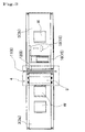
- Fig. 2 is a top view showing the gas-leakage detecting device of an embodiment of the invention.
- Fig. 3 is a top view of the main section of the gas-leakage detecting device of an embodiment of the invention.
- Fig. 4 is a front view of the main section of the gas-leakage detecting device of an embodiment of the invention.
- Fig. 5 is a top view showing the sealed container and pinhole-detection process of the invention.
- Fig. 6 is a top view showing the sealed container and pinhole-detection process of the invention.
- Fig. 7 is a top view showing the sealed container and pinhole-detection process of the invention.
- Fig. 8 is a top view showing the sealed container and pinhole-detection process of the invention.
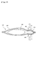
- Fig. 9 is a top view showing the sealed container and pinhole-detection process of the invention.
-
- The invention will be explained in more detail with reference to the attached drawings.
- As shown in Fig. 1, reference number 1 represents the leakage-detecting device for sealed packages of this embodiment that comprises a
base 2, and aconveyor belt 3 that continuously moves sealed packages W that are filled with detection gas for leakage detection to thebase 2; and where the conveyor belt 3 (in this embodiment, it comprises aninput conveyor 3a andoutput conveyer 3b) is equipped with a leakage-detection unit 4 that is located part way along the conveyor path and that detects leakage from the sealed packages W; and where the leakage-detection unit 4 comprises a vibration-application means 5 that applies vibration to the detection gas inside the sealed packages W, and a gas-detection means 6 that detects the detection gas that leaks from the sealed packages W. - To describe this in detail, the vibration-application means 5 comprises an striking device, as shown in Fig. 4, that strikes a sealed packages W from above after the sealed packages W has been moved to a specified location by the
conveyor belt 3. - In other words, a free-rocking
pressure plate 9 is attached by way of alink 8 to abracket 7 that is installed above theconveyor belt 3, and amotor 10, which rotates thelink 8 and causes thepressure plate 9 to move up and down, is connected to thelink 8, and the up and down movement of thepressure plate 9 causes it to strike the sealed package W. - On the other hand, the gas-detection means 6 comprises a
box 11 that forms a detection space A surrounding the vibration-application means 5 and the conveyed sealed package W, aprobe 12 that is located inside thisbox 11 and that draws in gas from inside the detection space A, and agas detector 13 that is connected to thisprobe 12. - The
probe 12 is spaced above and below the conveyor path of the sealed package W, and in this embodiment theprobe 12 is formed by forming a plurality of inlet holes that are spaced apart at specified intervals in the length direction of a pipe. - Moreover, this
probe 12 runs along the outer shape of the sealed package W, and preferably, it is arranged such that it completely surrounds the sealed package W. - Furthermore, there is a
blower 14 connected to thebox 11 that sucks in the gas from inside thebox 11 and discharges it to the outside, and as will be described later, when leakage is detected in the sealed package W, theblower 14 cleans the inside of thebox 11 before a new sealed package W is brought inside thebox 11. - On the other hand, down line from the
box 11, the leakage-detection unit 4 sends the sealed package W that was detected to be leaking on a conveying route that is different than the proper conveying route, or there is a work-removal apparatus that removes the work away from theconveyor belt 3. - This work-
removal apparatus 15 comprises abracket 16 that is fastened to thebase 2, an electric orpneumatic type plunger 17 that is attached to thebracket 16, aremoval plate 18 that is located such that it faces theconveyor belt 3 through a space, and that is moved back and forth by theplunger 17 in a direction orthogonal to the conveying direction of theconveyor belt 3 and moves the sealed package W. - The function of the leakage-detecting device 1 of this embodiment, constructed as described above, is explained below.
- The sealed packages W, which are filled with helium gas as the detection gas, are continuously supplied at specified intervals to the
conveyor belt 3 of this leakage-detecting device I by a separate detection-gas-filling apparatus. - The sealed packages W that are supplied in this way are conveyed to the leakage-
detection unit 4 by theconveyor belt 3. - A sealed package W that is conveyed to this leakage-
detection unit 4 is sent to the vibration-application means 5 inside thebox 11, and here by moving thepressure plate 9 of the vibration-application means 5 up and down, the sealed package W is pressed by thispressure plate 9. - Here, the gas inside the
box 11, which is constantly drawn in by theprobe 12, is sent to thegas detector 13. - When there is a pinhole or crack in the sealed package W, since the sealed package W has been filled with detection gas by the detection-gas-filling apparatus, the detection gas inside is released inside the
box 11 when that sealed package W is pressed by thepressure plate 9 in the vibration-application means 5, and it is drawn in by theprobe 12 and detected by thegas detector 13. - Defective items are detected in this way.
- When a defective item is detected in this way, the inside of the
box 11 is contaminated by the detection gas, so after the defective item has been output, theblower 14 operates and cleans out the inside of thebox 11, then inspection of the next sealed package W is performed. - Here, when it is determined that a sealed package W is good, the inside of the
box 11 is not contaminated, so theblower 14 remains stopped. - Furthermore, when a sealed package W that has been determined to be defective is output from the
box 11, as soon as this sealed package W has been conveyed to a specified location, theplunger 17 of the work-removal apparatus 15 operates and theremoval plate 18 that is attached to theplunger 17 pushes the sealed package W in the width direction of theconveyor belt 3 and changes its route, or removes it from theconveyor belt 3. - The leakage-detecting device 1 of this embodiment presses sealed packages W that are conveyed continuously at specified intervals, and when there is a pinhole or crack, it forcibly presses detection gas from the pinhole or crack, and can determine whether the package is defective or not.
- Therefore, it is possible to perform continuous inspection of the sealed packages W and to inspect all of the packages.
- The shapes and dimensions of the components shown in the embodiment are just one example, and various alterations are possible according to design needs.
- For example, it is possible to install a vibrator on the
conveyor belt 3 as the vibration-application means 5, and apply vibration to the sealed packages W on theconveyor belt 3 by applying vibration to theconveyor belt 3 by the vibrator. - Also, this vibrator can be an electrical-type, magnetic-type or mechanical-type vibrator.
- In Fig. 5 and Fig. 6, the sealed
container 100 of this invention comprises acontainer 200 made of plastic, and thecontents 300, such as food, and a gas-filledbody 400 that are stored in this container. - The gas-filled
body 400 is made of a layered material in which a chloroethylene or polypropylene film is layered on a thin aluminum film and formed into a small bag shape, and Helium gas is filled inside this gas-filled body. The material of the of the gas-filledbody 400 is not limited to that described above, however, in the case of just a plastic film, the gas can permeate the film, so it is preferred that an aluminum layer that has poor gas permeability be used. Also, it is possible to use another gas instead of helium gas as the filled gas, however, helium gas is chemically stable and does not react easily with food or chemicals, so taking these points into consideration, helium gas is the most preferable. - The gas-filled
body 400 is made separately from thecontainer 200, and is stored in thecontainer 200 together with thecontents 300. When doing this, the gas-filled body can be attached beforehand to a specified place inside the container for convenience of the pinhole inspection described below. - A sealed
container 100 that stores the contents and gas-filled body is inspected when shipped as a product to determine whether or not it has a pinhole. This pinhole inspection is performed using the following process. - First, a pressure means 500 that is located on the line presses the gas-filled
body 400 from the outside of the sealedcontainer 100 and breaks the gas-filledbody 400 by that pressure (see Fig. 6). Together with breaking the gas-filledbody 400, it disperses the helium gas filled inside it inside the sealedcontainer 100. Next, this is then inspected by a gas detector (not shown in the figure) that is also located on the line for whether or not there is any leakage of helium gas. Supposing that helium gas is leaking from the sealedcontainer 100, the gas detector reacts with it, and in this way, a pinhole in the sealed container is detected. - Fig. 7 to Fig. 9 show another embodiment of the invention.
- In these figures, the
container 200, thecontents 300 and gas-filledbody 400 of the sealedcontainer 100 are basically the same as those shown in Fig. 5 and Fig. 6. However, in the case of this embodiment, the gas-filledbody 400 is attached to and held between the inner sides of thecontainer 200. The means for attachment can be adhesive, two-sided tape or the like. - Also, pinhole inspection of the sealed
container 100 is performed as described below. - First, a pair of suction means 600, 600 that are located above and below the line become attached to the gas-filled
body 400 from the outside of the container 200 (see Fig. 8). Next, the suction means 600, 600 return to their respective original positions and pull the gas-filledbody 400 apart (see Fig. 9). At the same time, the helium gas is released from the gas-filled body and dispersed inside the sealed container. Next, suction from the suction means is stopped and everything is restored to its original position. - After that, the gas detector detects gas leakage as described above.
- In the embodiments shown in Fig. 5 to Fig. 9, the gas-filled
body 400 is formed as a small bag, however, it can also be formed into a capsule shape. - Also, in the embodiments described above, a pressure means 500 or suction means 600, 600 was used as the means for breaking the gas-filled
body 400, however, a method other than these, such as an electromagnetic radiation means located on the line that breaks the gas-filled body by heating up the aluminum of the gas-filled body and using the heat of the aluminum to melt the plastic, is also possible. In this case, in order to prevent thecontainer 200 from melting, a highly heat resistant plastic can be used as the material for the container, or the thin aluminum film can be used as the inner layer of the gas-filled body to avoid contact between the container and the aluminum. - Moreover, it is also possible to use a laser or ultrasonic waves as other means for breaking the gas-filled body. In these cases as well, by adequately changing the material of the gas-filled body or the container, it is possible to break just the gas-filled body from the outside of the container.
- The reference numbers used in the drawings are as follows:
- 1
- Leakage-detecting device
- 2
- Base
- 3
- Conveyor belt
- 3a
- Input conveyor
- 3b
- Output conveyor
- 4
- Leakage-detection unit
- 5
- Vibration-application means
- 6
- Gas-detection means
- 7
- Bracket
- 8
- Link
- 9
- Pressure plate
- 10
- Motor
- 11
- Box
- 12
- Probe
- 13
- Gas detector
- 14
- Blower
- 15
- Work-removal apparatus
- 16
- Bracket
- 17
- Plunger
- 18
- Removal plate
- W
- Sealed package
- 100
- Sealed container
- 200
- Container
- 300
- Contents
- 400
- Gas-filled body
- 500
- Pressure means
- 600
- Suction means
- This invention is constructed as described above, so by pressing or applying vibration to sealed packages that are continuously fed at specified intervals, when there is a pinhole or crack in the sealed packages, the detection gas is forcibly pressed out from the pinhole or crack and thus it is possible to determine whether the package is defective or not.
- Therefore, it is possible to continuously inspect the sealed packages W, as well as it is possible to inspect all of the packages.
- Also, with the invention described above, inspection of gas leakage is performed using a small amount of inspection gas that is filled into a small bag-shaped or capsule-shaped gas-filled body, so it is possible to avoid wasting expensive inspection gas. Moreover, unlike in the prior technology in which the inspection gas was filled directly into the container, there is no gas leakage when filling with gas, so it is possible to use a high-performance gas detector and perform the inspection accurately and speedily. Furthermore, since it is possible to perform the pinhole inspection process continuously in the same location as the process for filling the contents and gas-filled body, it is thus possible to simplify the equipment and line and to improve the efficiency of the work.
Claims (12)
- A leakage-detecting device for sealed packages comprising a conveyor belt that continuously moves sealed packages that have been filled with detection gas for detecting leakage, and a leakage-detection unit that is located along the conveying route of the conveyor and that detects leakage from said sealed packages; and wherein said leakage-detection unit comprises a vibration-application means that applies vibration to the detection gas inside said sealed packages and a gas-detection means that detects detection gas that leaks from said sealed packages.
- The leakage-detecting device for sealed packages of claim 1 wherein said vibration-application means is a striking apparatus that strikes the sealed packages on said conveyor belt.
- The leakage-detecting device for sealed packages of claim 1 wherein said vibration-application means is a vibrator that vibrates the sealed packages on said conveyor belt.
- The leakage-detecting device for sealed packages of any of the claims 1 to 3 wherein said gas-detection means comprises a box that forms a detection space around said vibration-application means and conveyed sealed packages, a probe that is located in this box and draws in gas from inside said detection space, and a gas detector that is connected to this probe.
- The leakage-detecting device for sealed packages of any of the claims 1 to 4 wherein said detection gas is helium.
- A sealed package in which a gas-filled body that can be broken from the outside of the container is stored inside the container.
- The sealed package of claim 6 wherein said gas-filled body is made of a layered material in which a chloroethylene or polypropylene film is layered on a thin aluminum film.
- The sealed package of claim 6 wherein the gas filled in said gas-filled body is helium.
- A pinhole detection method for sealed packages that breaks the gas-filled body inside the sealed package of claim 6 to disperse gas inside the sealed package and inspects whether or not there is gas leakage from that sealed package.
- The pinhole detection method of claim 9 wherein breaking of said gas-filled body is performed by a pressure means from the outside of the sealed package.
- The pinhole detection method of claim 9 wherein breaking of said gas-filled body is performed by a pair of suction means that pulls on both sides of the gas-filled body from the outside of the sealed package.
- The pinhole detection method of claim 9 wherein breaking of said gas-filled body is performed by electromagnetic radiation from the outside of the sealed package.
Applications Claiming Priority (5)
| Application Number | Priority Date | Filing Date | Title |
|---|---|---|---|
| JP2000302570 | 2000-10-02 | ||
| JP2000302570A JP2002107261A (en) | 2000-10-02 | 2000-10-02 | Leak detector for sealed package |
| JP2001192368A JP2003004580A (en) | 2001-06-26 | 2001-06-26 | Closed container and pinhole detection method for the closed container |
| JP2001192368 | 2001-06-26 | ||
| PCT/JP2001/008204 WO2002029377A1 (en) | 2000-10-02 | 2001-09-20 | Leakage detecting device for sealed packages |
Publications (2)
| Publication Number | Publication Date |
|---|---|
| EP1324014A1 true EP1324014A1 (en) | 2003-07-02 |
| EP1324014A4 EP1324014A4 (en) | 2007-06-27 |
Family
ID=26601384
Family Applications (1)
| Application Number | Title | Priority Date | Filing Date |
|---|---|---|---|
| EP01967761A Withdrawn EP1324014A4 (en) | 2000-10-02 | 2001-09-20 | Leakage detecting device for sealed packages |
Country Status (5)
| Country | Link |
|---|---|
| US (1) | US6966216B2 (en) |
| EP (1) | EP1324014A4 (en) |
| AU (2) | AU8808301A (en) |
| CA (1) | CA2424504A1 (en) |
| WO (1) | WO2002029377A1 (en) |
Cited By (6)
| Publication number | Priority date | Publication date | Assignee | Title |
|---|---|---|---|---|
| WO2004099751A3 (en) * | 2003-05-07 | 2005-04-28 | Leuven K U Res & Dev | Sealing process inspection device |
| EP1980833A1 (en) * | 2007-04-04 | 2008-10-15 | V-Tec Metaalbewerking B.V. | Leak test device |
| WO2009043647A1 (en) * | 2007-09-28 | 2009-04-09 | Evonik Degussa Gmbh | Device and method for determining the tightness of filled packagings |
| WO2013011329A3 (en) * | 2011-07-21 | 2013-05-23 | Packtester Limited | Seal integrity detector for sealed packages |
| US10408701B2 (en) | 2014-08-01 | 2019-09-10 | Cascade Technologies Holdings Limited | Leak detection system |
| FR3100888A1 (en) * | 2019-09-17 | 2021-03-19 | L'air Liquide, Societe Anonyme Pour L'etude Et L'exploitation Des Procedes Georges Claude | Method and equipment for detecting a packaging leakage |
Families Citing this family (18)
| Publication number | Priority date | Publication date | Assignee | Title |
|---|---|---|---|---|
| JP4235429B2 (en) * | 2002-10-17 | 2009-03-11 | キヤノン株式会社 | Method for measuring gas in sealed container, and method for manufacturing sealed container and image display device |
| GB0300586D0 (en) * | 2003-01-10 | 2003-02-12 | Btg Int Ltd | Therapeutic microfoam |
| US7257990B2 (en) * | 2005-04-25 | 2007-08-21 | General Atomics | Accelerated ultralow moisture permeation measurement |
| DE102008047820A1 (en) * | 2008-09-18 | 2010-04-01 | Haver & Boecker Ohg | Leak test method for bulk-filled bags, involves extracting air sample from closure of bag and detecting information contained in air sample bulk quantity |
| US8230722B1 (en) * | 2010-03-16 | 2012-07-31 | Sandia Corporation | Residual gas analysis device |
| EP2707631B1 (en) * | 2011-05-12 | 2017-02-15 | Fraunhofer Gesellschaft zur Förderung der angewandten Forschung E.V. | Test station and method for testing fluidic components |
| US8991236B2 (en) | 2011-08-01 | 2015-03-31 | Gm Global Technology Operations, Llc | Reconfigurable leak testing system |
| US8720253B2 (en) * | 2011-08-01 | 2014-05-13 | Gm Global Technology Operations, Llc | Reconfigurable leak testing system |
| ITMI20120791A1 (en) * | 2012-05-09 | 2013-11-10 | Rivoira S P A | NEW GAS MIXTURES FOR PACKAGING IN A PROTECTIVE ATMOSPHERE (MAP) OF FOOD PRODUCTS SUITABLE FOR NON-DESTRUCTIVE PACKAGING CONTROLS |
| US20150316441A1 (en) * | 2012-12-05 | 2015-11-05 | University Of Florida Research Foundation, Inc. | Method and apparatus for testing quality of seal and package integrity |
| DE102014225536B4 (en) * | 2014-12-11 | 2022-02-24 | Vitesco Technologies Germany Gmbh | Housing for a motor vehicle control device and method for manufacturing and testing the tightness of the housing |
| DE102015122592A1 (en) * | 2015-12-22 | 2017-06-22 | Airbus Defence and Space GmbH | A component device and method for detecting a damage of a bond in a component device |
| WO2017197521A1 (en) * | 2016-05-18 | 2017-11-23 | Lineriders Inc. | Apparatus and methodologies for leak detection using gas and infrared thermography |
| CN114264436B (en) * | 2020-09-16 | 2024-06-28 | 中国烟草总公司郑州烟草研究院 | System for online inspection of cigarette packaging seal |
| JP2022051001A (en) * | 2020-09-18 | 2022-03-31 | 株式会社イシダ | Production processing device |
| CN114739606B (en) * | 2022-03-11 | 2026-06-12 | 无锡先导智能装备股份有限公司 | Leak detection device |
| CN115980273B (en) * | 2022-12-27 | 2024-10-22 | 陕西燃气集团富平能源科技有限公司 | Helium gas storage leakage early warning system and method |
| CN117168712B (en) * | 2023-11-03 | 2024-04-02 | 宁德时代新能源科技股份有限公司 | Detection assembly, detection equipment and detection method thereof |
Family Cites Families (24)
| Publication number | Priority date | Publication date | Assignee | Title |
|---|---|---|---|---|
| US3091114A (en) * | 1959-12-17 | 1963-05-28 | Air Reduction | Method and apparatus for testing sealed packages for leaks |
| US3592049A (en) * | 1968-09-20 | 1971-07-13 | Safeway Stores | Method and apparatus for automatic leak detector |
| US3708949A (en) * | 1969-02-04 | 1973-01-09 | Safeway Stores | Method and apparatus for detection of leaks in seals of packages |
| US3591944A (en) * | 1969-03-03 | 1971-07-13 | Safeway Stores | Method and apparatus for detection of leaks in seals of packages |
| US3577769A (en) * | 1969-04-02 | 1971-05-04 | Gen Electric | Leak-detection system |
| JPS61288135A (en) * | 1985-06-17 | 1986-12-18 | Kishimoto Akira | Inspecting method for leak in sealed container |
| JPH07115697B2 (en) * | 1986-05-19 | 1995-12-13 | エービー テトラパック | Peeling method for packaging material |
| US4813268A (en) * | 1987-03-23 | 1989-03-21 | Superior Industries International, Inc. | Leakage detection apparatus for drum wheels and method therefore |
| JPH01226572A (en) * | 1988-02-24 | 1989-09-11 | Taiyo Shokai:Kk | Sealed bag containing mini gas-cylinder |
| US5345809A (en) * | 1989-06-09 | 1994-09-13 | Research Corporation Technologies, Inc. | Explosive detection screening system |
| US5010761A (en) * | 1990-03-01 | 1991-04-30 | Superior Industries International, Inc. | Automated leak detection apparatus and method therefor |
| US5029463A (en) | 1990-03-01 | 1991-07-09 | American Air Liquide | Leak detection device for in-line measurement of package integrity |
| US5369983A (en) * | 1992-04-17 | 1994-12-06 | Minnesota Mining And Manufacturing Company | Detection medium and method for use in hermetic seal testing |
| FR2703782B1 (en) * | 1993-04-08 | 1995-05-12 | Cit Alcatel | Leak detection installation for leak tightness testing of sealed packages. |
| US5499529A (en) * | 1993-06-02 | 1996-03-19 | The United States Of America As Represented By The United States Department Of Energy | Detecting small holes in packages |
| JP3149004B2 (en) * | 1993-08-31 | 2001-03-26 | 株式会社大塚製薬工場 | Pinhole inspection method for sealed packaging bags |
| US5388446A (en) * | 1993-10-18 | 1995-02-14 | The United States Of America As Represented By The United States Department Of Energy | Method and apparatus for container leakage testing |
| JPH07225171A (en) * | 1994-02-14 | 1995-08-22 | Yamaha Corp | Leak test method and leak test device |
| JP3551990B2 (en) * | 1994-12-06 | 2004-08-11 | 日本農薬株式会社 | Bag defect detection device in the case |
| JPH09120347A (en) | 1995-10-24 | 1997-05-06 | Brother Ind Ltd | Output device control device and method, and output device |
| FI970665A0 (en) * | 1996-04-15 | 1997-02-17 | Espoon Paineilma Oy | Foerfarande Foer identifier av laeckage i en foerpackning isynnerhet livsmedels- och laekemedelsfoerpackning samt foerbaettrande av haollbarheten hos vaetskeformiga livsmedel vilka aer foerpackade i aseptiska kartongfoerpackningar |
| US5939619A (en) * | 1996-12-02 | 1999-08-17 | True Technology, Inc. | Method and apparatus for detecting leaks in packaging |
| JP2933590B2 (en) * | 1997-03-07 | 1999-08-16 | 日本ボールドウィン株式会社 | Package and method and apparatus for opening the package |
| DE60001684T2 (en) * | 1999-04-07 | 2004-02-05 | Ishida Co., Ltd. | System for automatically checking packaging |
-
2001
- 2001-09-20 CA CA002424504A patent/CA2424504A1/en not_active Abandoned
- 2001-09-20 AU AU8808301A patent/AU8808301A/en active Pending
- 2001-09-20 US US10/398,047 patent/US6966216B2/en not_active Expired - Lifetime
- 2001-09-20 EP EP01967761A patent/EP1324014A4/en not_active Withdrawn
- 2001-09-20 WO PCT/JP2001/008204 patent/WO2002029377A1/en not_active Ceased
- 2001-09-20 AU AU2001288083A patent/AU2001288083B2/en not_active Ceased
Non-Patent Citations (2)
| Title |
|---|
| No further relevant documents disclosed * |
| See also references of WO0229377A1 * |
Cited By (9)
| Publication number | Priority date | Publication date | Assignee | Title |
|---|---|---|---|---|
| WO2004099751A3 (en) * | 2003-05-07 | 2005-04-28 | Leuven K U Res & Dev | Sealing process inspection device |
| US7673498B2 (en) | 2003-05-07 | 2010-03-09 | K.U. Leuven Research And Development | Sealing process inspection device |
| EP1620707B1 (en) * | 2003-05-07 | 2017-12-27 | K.U. Leuven Research and Development | Sealing process inspection device |
| EP1980833A1 (en) * | 2007-04-04 | 2008-10-15 | V-Tec Metaalbewerking B.V. | Leak test device |
| WO2009043647A1 (en) * | 2007-09-28 | 2009-04-09 | Evonik Degussa Gmbh | Device and method for determining the tightness of filled packagings |
| WO2013011329A3 (en) * | 2011-07-21 | 2013-05-23 | Packtester Limited | Seal integrity detector for sealed packages |
| US10408701B2 (en) | 2014-08-01 | 2019-09-10 | Cascade Technologies Holdings Limited | Leak detection system |
| FR3100888A1 (en) * | 2019-09-17 | 2021-03-19 | L'air Liquide, Societe Anonyme Pour L'etude Et L'exploitation Des Procedes Georges Claude | Method and equipment for detecting a packaging leakage |
| EP3795973A1 (en) | 2019-09-17 | 2021-03-24 | L'air Liquide, Societe Anonyme Pour L'etude Et L'exploitation Des Procedes Georges Claude | Method and device for detecting a sealing fault in packaging |
Also Published As
| Publication number | Publication date |
|---|---|
| WO2002029377A1 (en) | 2002-04-11 |
| US6966216B2 (en) | 2005-11-22 |
| US20040020268A1 (en) | 2004-02-05 |
| EP1324014A4 (en) | 2007-06-27 |
| AU2001288083B2 (en) | 2006-08-17 |
| AU8808301A (en) | 2002-04-15 |
| CA2424504A1 (en) | 2003-04-01 |
Similar Documents
| Publication | Publication Date | Title |
|---|---|---|
| AU2001288083B2 (en) | Leakage detecting device for sealed packages | |
| JP5840237B2 (en) | Leak detection method and apparatus | |
| CN1972844B (en) | Method and device for inspecting container | |
| JPH0658281B2 (en) | Method and device for inspecting sealability of closed container filled with filling material | |
| JP5863007B2 (en) | Liquid leak inspection device for containers | |
| JP2025520948A (en) | Inspection device for packaging machine and packaging machine having inspection device | |
| US6351984B1 (en) | Inspection method and device for non-destructive analysis of a container material | |
| JP6942152B2 (en) | Package inspection system | |
| JPH0737912B2 (en) | Inspection method for leaks in nitrogen gas filled packages | |
| JP2000046685A (en) | Method and apparatus for detecting air leakage in packaging bag | |
| JP5332181B2 (en) | Packaging defect inspection equipment for packaging products with thin film | |
| CN104471365B (en) | Multi-Stage Container Leak Testing | |
| JP2013036866A (en) | Sealing checkup apparatus for bottle | |
| EP3219626B1 (en) | Method and apparatus for leak detection for packages | |
| JP2002107261A (en) | Leak detector for sealed package | |
| JP5019024B2 (en) | Bottle container airtightness inspection device and method | |
| US5618990A (en) | Inspection system for detecting a leaking liquid and entering air | |
| JPH05180725A (en) | Seal inspection method for hermetically sealed products | |
| JP2017159932A (en) | Packaged product treatment apparatus | |
| JP3585343B2 (en) | Gas leak detection device and gas leak detection method for gas-filled container | |
| JP2003065881A (en) | Automatic inspection system for minute liquid leakage from containers | |
| JP3778469B2 (en) | Compressed air supply device | |
| JP2006184046A (en) | Liquid leakage inspection apparatus | |
| JP4551856B2 (en) | Shrink packaging defect detection device | |
| JP3808615B2 (en) | Container positioning device |
Legal Events
| Date | Code | Title | Description |
|---|---|---|---|
| PUAI | Public reference made under article 153(3) epc to a published international application that has entered the european phase |
Free format text: ORIGINAL CODE: 0009012 |
|
| 17P | Request for examination filed |
Effective date: 20030325 |
|
| AK | Designated contracting states |
Designated state(s): AT BE CH CY DE DK ES FI FR GB GR IE IT LI LU MC NL PT SE TR |
|
| AX | Request for extension of the european patent |
Extension state: AL LT LV MK RO SI |
|
| RBV | Designated contracting states (corrected) |
Designated state(s): AT BE CH CY DE FR GB LI SE |
|
| A4 | Supplementary search report drawn up and despatched |
Effective date: 20070525 |
|
| 17Q | First examination report despatched |
Effective date: 20071106 |
|
| STAA | Information on the status of an ep patent application or granted ep patent |
Free format text: STATUS: THE APPLICATION IS DEEMED TO BE WITHDRAWN |
|
| 18D | Application deemed to be withdrawn |
Effective date: 20091120 |