EP1323896A2 - Supplemental seal for the chordal hinge seal in a gas turbine - Google Patents
Supplemental seal for the chordal hinge seal in a gas turbine Download PDFInfo
- Publication number
- EP1323896A2 EP1323896A2 EP02258876A EP02258876A EP1323896A2 EP 1323896 A2 EP1323896 A2 EP 1323896A2 EP 02258876 A EP02258876 A EP 02258876A EP 02258876 A EP02258876 A EP 02258876A EP 1323896 A2 EP1323896 A2 EP 1323896A2
- Authority
- EP
- European Patent Office
- Prior art keywords
- seal
- inner rail
- extending
- turbine
- cloth
- Prior art date
- Legal status (The legal status is an assumption and is not a legal conclusion. Google has not performed a legal analysis and makes no representation as to the accuracy of the status listed.)
- Granted
Links
Images





Classifications
-
- F—MECHANICAL ENGINEERING; LIGHTING; HEATING; WEAPONS; BLASTING
- F01—MACHINES OR ENGINES IN GENERAL; ENGINE PLANTS IN GENERAL; STEAM ENGINES
- F01D—NON-POSITIVE DISPLACEMENT MACHINES OR ENGINES, e.g. STEAM TURBINES
- F01D11/00—Preventing or minimising internal leakage of working-fluid, e.g. between stages
-
- F—MECHANICAL ENGINEERING; LIGHTING; HEATING; WEAPONS; BLASTING
- F01—MACHINES OR ENGINES IN GENERAL; ENGINE PLANTS IN GENERAL; STEAM ENGINES
- F01D—NON-POSITIVE DISPLACEMENT MACHINES OR ENGINES, e.g. STEAM TURBINES
- F01D11/00—Preventing or minimising internal leakage of working-fluid, e.g. between stages
- F01D11/005—Sealing means between non relatively rotating elements
-
- F—MECHANICAL ENGINEERING; LIGHTING; HEATING; WEAPONS; BLASTING
- F01—MACHINES OR ENGINES IN GENERAL; ENGINE PLANTS IN GENERAL; STEAM ENGINES
- F01D—NON-POSITIVE DISPLACEMENT MACHINES OR ENGINES, e.g. STEAM TURBINES
- F01D9/00—Stators
- F01D9/02—Nozzles; Nozzle boxes; Stator blades; Guide conduits, e.g. individual nozzles
- F01D9/04—Nozzles; Nozzle boxes; Stator blades; Guide conduits, e.g. individual nozzles forming ring or sector
- F01D9/041—Nozzles; Nozzle boxes; Stator blades; Guide conduits, e.g. individual nozzles forming ring or sector using blades
-
- F—MECHANICAL ENGINEERING; LIGHTING; HEATING; WEAPONS; BLASTING
- F16—ENGINEERING ELEMENTS AND UNITS; GENERAL MEASURES FOR PRODUCING AND MAINTAINING EFFECTIVE FUNCTIONING OF MACHINES OR INSTALLATIONS; THERMAL INSULATION IN GENERAL
- F16J—PISTONS; CYLINDERS; SEALINGS
- F16J15/00—Sealings
- F16J15/02—Sealings between relatively-stationary surfaces
- F16J15/06—Sealings between relatively-stationary surfaces with solid packing compressed between sealing surfaces
- F16J15/08—Sealings between relatively-stationary surfaces with solid packing compressed between sealing surfaces with exclusively metal packing
- F16J15/0806—Sealings between relatively-stationary surfaces with solid packing compressed between sealing surfaces with exclusively metal packing characterised by material or surface treatment
- F16J15/0812—Sealings between relatively-stationary surfaces with solid packing compressed between sealing surfaces with exclusively metal packing characterised by material or surface treatment with a braided or knitted body
Definitions
- the present invention relates to seals in a gas turbine for supplementing the chordal hinge seals between turbine nozzle segments and a turbine nozzle support ring and particularly relates to supplementary seals for substantially minimizing or eliminating leakage losses past the chordal hinge seals.
- the first-stage nozzles typically include an annular array or assemblage of cast nozzle segments each containing one or more nozzle stator vanes per segment. Each first-stage nozzle segment also includes inner and outer band portions spaced radially from one another. Upon assembly of the nozzle segments, the stator vanes are circumferentially spaced from one another to form an annular array thereof between annular inner and outer bands.
- a nozzle retaining ring coupled to the outer band of the first-stage nozzles supports the first-stage nozzles in the gas flow path of the turbine.
- An annular nozzle support ring preferably split at a horizontal midline, is engaged by the inner band and supports the first-stage nozzles against axial movement.
- eighteen cast segments are provided with two vanes per segment.
- the annular array of segments are sealed one to the other along adjoining circumferential edges by side seals.
- the side seals seal between a high pressure region radially inwardly of the inner band, i.e., compressor discharge air at high pressure, and the hot gases of combustion in the hot gas flow path which are at a lower pressure.
- Chordal hinge seals are used to seal between the inner band of the first-stage nozzles and an axially facing surface of the nozzle support ring.
- Each chordal hinge seal includes an axial projection which extends linearly along a chordline of the inner band portion of each nozzle segment. Particularly, the chordal hinge seal extends along an inner rail of each segment and which rail extends radially inwardly of the inner band portion. The chordal hinge seal projection lies in sealing engagement with the axially opposite facing sealing surface of the nozzle support ring.
- chordal hinge seals are inadequate to prevent leakage flow as the chordal hinge seal projections lose contact with the sealing surface of the nozzle support ring. Consequently, there is a need for a supplemental seal at the interface of the first-stage nozzles and nozzle support ring to minimize or eliminate the leakage flow past the chordal hinge seals.
- a supplemental seal between the first-stage nozzles and the nozzle support ring which eliminates or minimizes leakage past the chordal hinge seals and which is readily and easily installed.
- the supplemental seal includes at least one and preferably two back-to-back sheet metal plates or shims wrapped in a woven metallic cloth attached to the inner rail of each nozzle segment.
- the supplemental seal extends from a groove formed in the radial inward facing surface of the inner rail to a distal margin which engages against a first surface of the nozzle support ring at a location radially inwardly of the chordal hinge seal. The distal margin is preloaded and it, together with the high pressure compressor discharge air in the high pressure region of the turbine, biases the cloth seal against the annular surface of the nozzle support ring.
- each seal segment extends linearly in a chord-wise direction relative to the turbine axis and is provided in lengths corresponding to the circumferential extent of each inner rail.
- each seal projects generally axially along the radial inward facing surface of the inner rail toward the nozzle support ring.
- a distal margin turns in a generally radially inward direction to form a flexible distal leg or margin in sealing engagement with the sealing surface of the nozzle support ring.
- the shims in the leg of the distal margin of each seal are slit back from their distal edge to form a plurality of fingers.
- the fingers of one shim leg overlie the slits between the fingers of the other shim leg. That is, the slits of the shims are staggered in a chord-wise direction relative to one another such that the slits of each shim leg are effectively sealed by the fingers of the opposing shim leg.
- the slits afford flexibility to the sealing surface of the supplemental seal leg.
- a turbine comprising a turbine nozzle support ring having a generally axially facing first surface, a turbine nozzle segment having at least one stator vane and a radially inwardly extending inner rail having a second surface in axial opposition to the first surface, a seal extending from a radial inward facing surface of the inner rail for sealing engagement against the first surface to form a seal therewith, the seal including a seal segment having at least a first plate, an overlay of a woven metallic cloth and a distal margin covered by the cloth and sealingly engaging the first surface and a bracket extending along the inner rail and at least a portion of one side of the seal segment to support the seal segment from the inner rail, the margin of the seal segment being flexible and preloaded to seal against the first surface.
- a turbine comprising a turbine nozzle support ring having a generally axially facing first surface, a plurality of turbine nozzle segments each having at least one stator vane and a radially inwardly extending inner rail having a second surface in axial opposition to the first surface, a seal comprised of a plurality of seal segments each extending from a radial inward facing surface of the inner rail for sealing engagement against the first surface to form a seal therewith, each seal segment including a first plate, an overlay of a woven metallic cloth and a distal margin covered by the cloth and engaging the first surface and a plurality of brackets extending along the inner rail and one side of the seal segments to support the seal segments from the inner rail, the margins of the seal segments being flexible and preloaded to seal against the first surface.
- Turbine 10 receives hot gases of combustion from an annular array of combustors, not shown, which transmit the hot gases through a transition piece 12 for flow along an annular hot gas path 14.
- Turbine stages are disposed along the hot gas path 14.
- Each stage comprises a plurality of circumferentially spaced buckets mounted on and forming part of the turbine rotor and a plurality of circumferentially spaced stator vanes forming an annular array of nozzles.
- the first stage includes a plurality of circumferentially-spaced buckets 16 mounted on a first-stage rotor wheel 18 and a plurality of circumferentially-spaced stator vanes 20.
- the second stage includes a plurality of buckets 22 mounted on a rotor wheel 24 and a plurality of circumferentially-spaced stator vanes 26. Additional stages may be provided, for example, a third stage comprised of a plurality of circumferentially-spaced buckets 28 mounted on a third-stage rotor wheel 30 and a plurality of circumferentially-spaced stator vanes 32.
- the stator vanes 20, 26 and 32 are mounted on and fixed to a turbine casing, while the buckets 16, 22 and 28 and wheels 18, 24 and 30 form part of the turbine rotor.
- Between the rotor wheels are spacers 34 and 36 which also form part of the turbine rotor. It will be appreciated that compressor discharge air is located in a region 37 disposed radially inwardly of the first stage and that such air in region 37 is at a higher pressure than the pressure of the hot gases flowing along the hot gas path 14.
- the stator vanes 20 forming the first-stage nozzles are disposed between inner and outer bands 38 and 40, respectively, supported from the turbine casing.
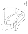
- the nozzles of the first stage are formed of a plurality of nozzle segments 41 ( Figure 3) each mounting one, preferably two, stator vanes extending between inner and outer band portions and arranged in an annular array of segments.
- a nozzle retaining ring 42 connected to the turbine casing is coupled to the outer band and secures the first-stage nozzle.
- a nozzle support ring 44 radially inwardly of the inner band 38 of the first-stage nozzles engages the inner band 38.
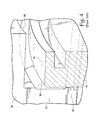
- the interface between the inner band 38 and the nozzle support ring 44 includes an inner rail 52 ( Figure 2).
- the inner rail 52 includes a chord-wise, linearly extending axial projection 48, generally and collectively hereinafter referred to as a chordal hinge seal 46.
- Projection 48 extends along an axial facing surface 50 of the inner rail 52 which forms an integral part of each nozzle segment and specifically the inner band 38.
- the projection 48 engages a first annular surface 54 of the nozzle support ring 44. It will be appreciated that high pressure compressor discharge air lies in the region 37 and lower pressure hot gases flowing in the hot gas path 14 lie on the opposite side of the seal 48.
- the chordal hinge seal 46 is thus intended to seal against leakage from the high pressure region 37 into the lower pressure region of the hot gas path 14.
- a supplemental seal for sealing between the first-stage nozzles and the nozzle support ring 44.
- the supplemental seal is provided in seal segments 73.
- Each segment 73 includes a chord-wise linearly extending cloth seal formed by back-to-back sheet metal shims wrapped in preferably a woven metallic cloth and secured to a first-stage nozzle segment.
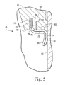
- the supplemental seal 70 includes one, and preferably a pair of sheet metal plates or shims 72 and 74 overlaid on both sides by a woven metallic cloth 76.
- Seal 70 also includes a bracket 80 which extends chord-wise and linearly along one side of a proximal margin 77 of the seal and provides a rigid support for the seal.
- the metallic cloth and shims of margin 77 are integrally secured to the bracket 80 along the interfaces of the bracket 80 and cloth 76, for example, by welding.
- each seal segment 73 is shaped to provide a proximal margin 77, a central body portion 82 and a distal margin 84.
- a groove 86 is formed in the inner rail 52 and extends linearly in a chord-wise direction opening through a radial inward face 88 of the inner rail.
- the groove 86 also has an offset recess 90 which receives a flange 92 formed on the bracket 80.
- each seal segment 73 is bent or folded from the proximal margin 77 to extend in a generally axial direction toward the nozzle support ring 44 and in direct underlying relation to the inner radial face 88 of the inner rail 52.
- the seal segment 73 then turns generally radially inwardly to form the distal margin 84.
- the margin 84 engages and bears against the sealing surface 54 of the nozzle support ring 44 to seal against surface 54.
- the woven metallic cloth of the distal margin 84 bears against the sealing surface 54. It will be appreciated that the shims or plates 72 and 74 are preloaded to maintain the margin 84 in sealing engagement against surface 54. Also, in use, the high pressure region 37 of the turbine biases the flexible margin 84 into engagement with the surface 54.
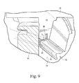
- the portions of the shims 72 and 74 forming the distal margin 84 are slit at laterally spaced locations along the seal 70 to form fingers 92 and 94, respectively.
- the shim 72 is slit at 96 at chord-wise spaced locations therealong to form discrete fingers 98.
- the shim 74 is likewise slit at 100 at chord-wise spaced locations therealong to form discrete fingers 104.
- the slits 96 and 100 are staggered in a chord-wise direction relative to one another such that the fingers 104 formed by the slits 100 overlie the slits 96 between the fingers 98 of shim 72.
- the fingers 98 and 104 alternate along the length of the distal margin 84 of the seal segment 73.
- the fingers render the distal margin flexible, thereby affording an effective seal with the sealing surface 54.
- the overlapping of the slits by the fingers also affords a sealing action inhibiting flow between the slits.
- FIG 10 there is illustrated a portion of a preferred metallic cloth overlaying a shim, for example, shim 72.
- the cloth overlays in the form of a Dutch twill weave, preferably formed of L605 or Hanes 188 material, and, with the relatively dense weave, forms an effective seal and wear surface.
- the supplemental seal segments are provided preferably in the same number as the number of nozzle segments. Consequently, the supplemental seal segments overlie the joints between the nozzle segments and butt endwise with one another, thereby to reduce nozzle intersegment leakage, as well as leakage past the chordal hinge seals. As illustrated in Figure 9, the ends of the seal segment 73 may be overlapped relative to one another to effect enhanced sealing adjacent the gap between the nozzle segments.
Landscapes
- Engineering & Computer Science (AREA)
- General Engineering & Computer Science (AREA)
- Mechanical Engineering (AREA)
- Turbine Rotor Nozzle Sealing (AREA)
- Gasket Seals (AREA)
Abstract
Description
Claims (10)
- A turbine (10) comprising:a turbine nozzle support ring (44) having a generally axially facing first surface (54);a turbine nozzle segment (41) having at least one stator vane (20) and a radially inwardly extending inner rail (52) having a second surface (50) in axial opposition to said first surface;a seal (70) extending from a radial inward facing surface (88) of said inner rail for sealing engagement against said first surface to form a seal therewith;said seal including a seal segment (73) having at least a first plate (72), an overlay of a woven metallic cloth (76) and a distal margin (84) covered by said cloth and sealingly engaging said first surface; anda bracket (80) extending along said inner rail and at least a portion of one side of said seal segment to support said seal segment from said inner rail, said margin (84) of said seal segment being flexible and preloaded to seal against said first surface.
- A turbine according to Claim 1 wherein said seal segment includes a second plate (74, said plates lying back-to-back with one another, said cloth extending as an overlay along opposite sides of said first and second plates.
- A turbine according to Claim 2 wherein said seal extends linearly in a chord-wise direction along said inner rail, said plates having slits (96, 100) extending from edges thereof and along said margin to provide flexibility to said seal.
- A turbine according to Claim 1, 2 or 3 wherein said inner rail (52) has a projection (48) extending axially from said inner rail for sealing engagement against said first surface and forming a second seal therewith.
- A turbine according to Claim 1, 2 or 3 wherein said inner rail (52) has a groove (86) extending in a chord-wise direction and opening through said inward facing surface thereof, said bracket and said one side seal portion lying in said groove.
- A turbine (10) comprising:a turbine nozzle support ring (44) having a generally axially facing first surface (54);a plurality of turbine nozzle segments (41) each having at least one stator vane (20) and a radially inwardly extending inner rail (52) having a second surface (50) in axial opposition to said first surface;a seal (70) comprised of a plurality of seal segments (73) each extending from a radial inward facing surface (88) of said inner rail (52) for sealing engagement against said first surface (54) to form a seal therewith;each said seal segment including a first plate (72), an overlay of a woven metallic cloth (76) and a distal margin (84) covered by said cloth and engaging said first surface; anda plurality of brackets (80) extending along said inner rail and one side of said seal segments to support said seal segments from said inner rail, said margins of said seal segments being flexible and preloaded to seal against said first surface.
- A turbine according to Claim 6 wherein each said seal segment includes a second plate (74), said first and second plates of each said seal segment lying back-to-back with one another, said cloth (76) extending as an overlay along opposite sides of said first and second plates.
- A turbine according to Claim 6 wherein each of said seal segments extends in a chord-wise direction and has a chord-wise extent corresponding to the chord-wise extent of each inner rail.
- A turbine according to Claim 6 wherein each said seal segment includes a second plate (74), said first and second plates of each said seal body lying back-to-back with one another, said cloth extending as an overlay along opposite sides of said first and second plates, said plates having slits (96, 100) extending from edges thereof and along said margin to provide flexibility to said seal.
- A turbine according to Claim 6 wherein each said inner rail (52) has a projection (48) extending axially therefrom for sealing engagement against said first surface and forming a second seal therewith.
Applications Claiming Priority (2)
| Application Number | Priority Date | Filing Date | Title |
|---|---|---|---|
| US28931 | 2001-12-28 | ||
| US10/028,931 US6609885B2 (en) | 2001-12-28 | 2001-12-28 | Supplemental seal for the chordal hinge seal in a gas turbine |
Publications (3)
| Publication Number | Publication Date |
|---|---|
| EP1323896A2 true EP1323896A2 (en) | 2003-07-02 |
| EP1323896A3 EP1323896A3 (en) | 2004-03-17 |
| EP1323896B1 EP1323896B1 (en) | 2006-08-16 |
Family
ID=21846288
Family Applications (1)
| Application Number | Title | Priority Date | Filing Date |
|---|---|---|---|
| EP02258876A Expired - Lifetime EP1323896B1 (en) | 2001-12-28 | 2002-12-23 | Turbine with a static seal |
Country Status (5)
| Country | Link |
|---|---|
| US (1) | US6609885B2 (en) |
| EP (1) | EP1323896B1 (en) |
| JP (1) | JP4130579B2 (en) |
| KR (1) | KR100767892B1 (en) |
| DE (1) | DE60213946T2 (en) |
Cited By (7)
| Publication number | Priority date | Publication date | Assignee | Title |
|---|---|---|---|---|
| EP1323898A3 (en) * | 2001-12-28 | 2004-03-17 | General Electric Company | Supplemental seal for the chordal hinge seal in a gas turbine |
| EP1323900A3 (en) * | 2001-12-28 | 2004-03-24 | General Electric Company | Supplemental seal for the chordal hinge seal in a gas turbine |
| EP2187002A1 (en) * | 2008-11-12 | 2010-05-19 | Siemens Aktiengesellschaft | Gas turbine nozzle arrangement and gas turbine |
| CN102465719A (en) * | 2010-11-11 | 2012-05-23 | 通用电气公司 | Transition piece seal assembly with seal cover |
| EP2960439A1 (en) * | 2014-06-26 | 2015-12-30 | Siemens Aktiengesellschaft | Turbomachine with an outer sealing and use of the turbomachine |
| US9506364B2 (en) | 2010-01-12 | 2016-11-29 | Kawasaki Jukogyo Kabushiki Kaisha | Sealing arrangement and gas turbine engine with the sealing arrangement |
| WO2020234007A1 (en) * | 2019-05-21 | 2020-11-26 | Rolls-Royce Deutschland Ltd & Co Kg | Device for sealing a gap between two components of a turbine of a gas turbine engine |
Families Citing this family (21)
| Publication number | Priority date | Publication date | Assignee | Title |
|---|---|---|---|---|
| GB2404274B (en) * | 2003-07-24 | 2007-07-04 | Pelikon Ltd | Control of electroluminescent displays |
| US7094026B2 (en) * | 2004-04-29 | 2006-08-22 | General Electric Company | System for sealing an inner retainer segment and support ring in a gas turbine and methods therefor |
| US7052234B2 (en) | 2004-06-23 | 2006-05-30 | General Electric Company | Turbine vane collar seal |
| US7160078B2 (en) * | 2004-09-23 | 2007-01-09 | General Electric Company | Mechanical solution for rail retention of turbine nozzles |
| US20070149031A1 (en) * | 2005-12-22 | 2007-06-28 | United Technologies Corporation. | Reduced leakage finger seal |
| US7850425B2 (en) * | 2007-08-10 | 2010-12-14 | General Electric Company | Outer sidewall retention scheme for a singlet first stage nozzle |
| US8070427B2 (en) * | 2007-10-31 | 2011-12-06 | General Electric Company | Gas turbines having flexible chordal hinge seals |
| US8413447B2 (en) * | 2009-09-16 | 2013-04-09 | General Electric Company | Fuel nozzle cup seal |
| US9482107B2 (en) | 2009-09-28 | 2016-11-01 | Siemens Aktiengesellschaft | Gas turbine nozzle arrangement and gas turbine |
| US8613451B2 (en) | 2010-11-29 | 2013-12-24 | General Electric Company | Cloth seal for turbo-machinery |
| DE102010055435B4 (en) | 2010-12-21 | 2018-03-29 | Rolls-Royce Deutschland Ltd & Co Kg | Innendeckband a gas turbine and method for producing a Innenendeckbandes |
| US9097129B2 (en) | 2012-05-31 | 2015-08-04 | United Technologies Corporation | Segmented seal with ship lap ends |
| US9759081B2 (en) | 2013-10-08 | 2017-09-12 | General Electric Company | Method and system to facilitate sealing in gas turbines |
| US9828868B2 (en) | 2014-09-11 | 2017-11-28 | United Technologies Corporation | Hinged seal using wire mesh |
| US10280777B2 (en) * | 2014-12-19 | 2019-05-07 | General Electric Company | System and method including a circumferential seal assembly to facilitate sealing in a turbine |
| US20170051983A1 (en) * | 2015-08-18 | 2017-02-23 | Arvos Inc. | Flexible seal for a rotary regenerative preheater |
| US10830069B2 (en) * | 2016-09-26 | 2020-11-10 | General Electric Company | Pressure-loaded seals |
| US10519807B2 (en) | 2017-04-19 | 2019-12-31 | Rolls-Royce Corporation | Seal segment retention ring with chordal seal feature |
| KR101985109B1 (en) * | 2017-11-21 | 2019-05-31 | 두산중공업 주식회사 | First stage turbine vane support structure and gas turbine including the same |
| US10968777B2 (en) * | 2019-04-24 | 2021-04-06 | Raytheon Technologies Corporation | Chordal seal |
| US11878807B2 (en) * | 2020-05-07 | 2024-01-23 | Raytheon Company | Adaptive air flow inhibitor seal for aircraft propulsion systems |
Family Cites Families (18)
| Publication number | Priority date | Publication date | Assignee | Title |
|---|---|---|---|---|
| US4184689A (en) * | 1978-10-02 | 1980-01-22 | United Technologies Corporation | Seal structure for an axial flow rotary machine |
| US4314793A (en) * | 1978-12-20 | 1982-02-09 | United Technologies Corporation | Temperature actuated turbine seal |
| US4645217A (en) | 1985-11-29 | 1987-02-24 | United Technologies Corporation | Finger seal assembly |
| US4883405A (en) * | 1987-11-13 | 1989-11-28 | The United States Of America As Represented By The Secretary Of The Air Force | Turbine nozzle mounting arrangement |
| US4815933A (en) * | 1987-11-13 | 1989-03-28 | The United States Of America As Represented By The Secretary Of The Air Force | Nozzle flange attachment and sealing arrangement |
| US4863343A (en) | 1988-05-16 | 1989-09-05 | Westinghouse Electric Corp. | Turbine vane shroud sealing system |
| US5149250A (en) * | 1991-02-28 | 1992-09-22 | General Electric Company | Gas turbine vane assembly seal and support system |
| US5474306A (en) | 1992-11-19 | 1995-12-12 | General Electric Co. | Woven seal and hybrid cloth-brush seals for turbine applications |
| US5372476A (en) * | 1993-06-18 | 1994-12-13 | General Electric Company | Turbine nozzle support assembly |
| US5657998A (en) | 1994-09-19 | 1997-08-19 | General Electric Company | Gas-path leakage seal for a gas turbine |
| US5509669A (en) | 1995-06-19 | 1996-04-23 | General Electric Company | Gas-path leakage seal for a gas turbine |
| US5586773A (en) | 1995-06-19 | 1996-12-24 | General Electric Company | Gas-path leakage seal for a gas turbine made from metallic mesh |
| US5934687A (en) | 1997-07-07 | 1999-08-10 | General Electric Company | Gas-path leakage seal for a turbine |
| US5915697A (en) * | 1997-09-22 | 1999-06-29 | General Electric Company | Flexible cloth seal assembly |
| US6162014A (en) | 1998-09-22 | 2000-12-19 | General Electric Company | Turbine spline seal and turbine assembly containing such spline seal |
| US6164656A (en) * | 1999-01-29 | 2000-12-26 | General Electric Company | Turbine nozzle interface seal and methods |
| US6719295B2 (en) * | 2001-12-28 | 2004-04-13 | General Electric Company | Supplemental seal for the chordal hinge seals in a gas turbine |
| US6637751B2 (en) * | 2001-12-28 | 2003-10-28 | General Electric Company | Supplemental seal for the chordal hinge seals in a gas turbine |
-
2001
- 2001-12-28 US US10/028,931 patent/US6609885B2/en not_active Expired - Fee Related
-
2002
- 2002-12-23 DE DE60213946T patent/DE60213946T2/en not_active Expired - Lifetime
- 2002-12-23 EP EP02258876A patent/EP1323896B1/en not_active Expired - Lifetime
- 2002-12-27 KR KR1020020084918A patent/KR100767892B1/en not_active Expired - Fee Related
- 2002-12-27 JP JP2002378999A patent/JP4130579B2/en not_active Expired - Fee Related
Cited By (11)
| Publication number | Priority date | Publication date | Assignee | Title |
|---|---|---|---|---|
| EP1323898A3 (en) * | 2001-12-28 | 2004-03-17 | General Electric Company | Supplemental seal for the chordal hinge seal in a gas turbine |
| EP1323900A3 (en) * | 2001-12-28 | 2004-03-24 | General Electric Company | Supplemental seal for the chordal hinge seal in a gas turbine |
| EP2187002A1 (en) * | 2008-11-12 | 2010-05-19 | Siemens Aktiengesellschaft | Gas turbine nozzle arrangement and gas turbine |
| WO2010054870A1 (en) * | 2008-11-12 | 2010-05-20 | Siemens Aktiengesellschaft | Gas turbine nozzle arrangement and gas turbine |
| US9506364B2 (en) | 2010-01-12 | 2016-11-29 | Kawasaki Jukogyo Kabushiki Kaisha | Sealing arrangement and gas turbine engine with the sealing arrangement |
| EP2525063A4 (en) * | 2010-01-12 | 2017-01-11 | Kawasaki Jukogyo Kabushiki Kaisha | Seal structure and gas turbine engine provided therewith |
| CN102465719A (en) * | 2010-11-11 | 2012-05-23 | 通用电气公司 | Transition piece seal assembly with seal cover |
| EP2960439A1 (en) * | 2014-06-26 | 2015-12-30 | Siemens Aktiengesellschaft | Turbomachine with an outer sealing and use of the turbomachine |
| WO2015197626A1 (en) * | 2014-06-26 | 2015-12-30 | Siemens Aktiengesellschaft | Turbomachine with an outer sealing and use of the turbomachine |
| US10513940B2 (en) | 2014-06-26 | 2019-12-24 | Siemens Aktiengesellschaft | Turbomachine with an outer sealing and use of the turbomachine |
| WO2020234007A1 (en) * | 2019-05-21 | 2020-11-26 | Rolls-Royce Deutschland Ltd & Co Kg | Device for sealing a gap between two components of a turbine of a gas turbine engine |
Also Published As
| Publication number | Publication date |
|---|---|
| DE60213946T2 (en) | 2007-09-06 |
| KR20030057427A (en) | 2003-07-04 |
| JP2003227354A (en) | 2003-08-15 |
| US20030123980A1 (en) | 2003-07-03 |
| EP1323896A3 (en) | 2004-03-17 |
| EP1323896B1 (en) | 2006-08-16 |
| DE60213946D1 (en) | 2006-09-28 |
| JP4130579B2 (en) | 2008-08-06 |
| US6609885B2 (en) | 2003-08-26 |
| KR100767892B1 (en) | 2007-10-17 |
Similar Documents
| Publication | Publication Date | Title |
|---|---|---|
| EP1323896B1 (en) | Turbine with a static seal | |
| EP1323901B1 (en) | Supplemental seal for the chordal hinge seal in a gas turbine | |
| EP1323898B1 (en) | Supplemental seal for the chordal hinge seal in a gas turbine | |
| US6599089B2 (en) | Supplemental seal for the chordal hinge seal in a gas turbine | |
| EP1323899B1 (en) | Gasturbine with a supplemental seal for the chordal hinge seal | |
| US6572331B1 (en) | Supplemental seal for the chordal hinge seals in a gas turbine | |
| US6637753B2 (en) | Supplemental seal for the chordal hinge seals in a gas turbine | |
| EP1323895B1 (en) | Supplemental seal for the chordal hinge seals in a gas turbine | |
| EP1323891B1 (en) | Supplemental seal for the chordal hinge seals in a gas turbine | |
| EP1323897B1 (en) | Turbine with a supplemental seal for the chordal hinge sealing |
Legal Events
| Date | Code | Title | Description |
|---|---|---|---|
| PUAI | Public reference made under article 153(3) epc to a published international application that has entered the european phase |
Free format text: ORIGINAL CODE: 0009012 |
|
| AK | Designated contracting states |
Designated state(s): AT BE BG CH CY CZ DE DK EE ES FI FR GB GR IE IT LI LU MC NL PT SE SI SK TR |
|
| AX | Request for extension of the european patent |
Extension state: AL LT LV MK RO |
|
| RIN1 | Information on inventor provided before grant (corrected) |
Inventor name: KELLOCK, IAIN ROBERTSON Inventor name: AKSIT, MAHMUT Inventor name: SAFI, AHMAD Inventor name: MOHAMMED-FAKIR, ABDUL-AZEEZ |
|
| PUAL | Search report despatched |
Free format text: ORIGINAL CODE: 0009013 |
|
| AK | Designated contracting states |
Kind code of ref document: A3 Designated state(s): AT BE BG CH CY CZ DE DK EE ES FI FR GB GR IE IT LI LU MC NL PT SE SI SK TR |
|
| AX | Request for extension of the european patent |
Extension state: AL LT LV MK RO |
|
| 17P | Request for examination filed |
Effective date: 20040917 |
|
| AKX | Designation fees paid |
Designated state(s): CH DE FR GB IT LI |
|
| 17Q | First examination report despatched |
Effective date: 20050121 |
|
| GRAP | Despatch of communication of intention to grant a patent |
Free format text: ORIGINAL CODE: EPIDOSNIGR1 |
|
| RTI1 | Title (correction) |
Free format text: TURBINE WITH A SUPPLEMENTAL SEAL FOR THE CHORDAL HINGE SEAL |
|
| RTI1 | Title (correction) |
Free format text: TURBINE WITH A STATIC SEAL |
|
| GRAS | Grant fee paid |
Free format text: ORIGINAL CODE: EPIDOSNIGR3 |
|
| GRAA | (expected) grant |
Free format text: ORIGINAL CODE: 0009210 |
|
| AK | Designated contracting states |
Kind code of ref document: B1 Designated state(s): CH DE FR GB IT LI |
|
| REG | Reference to a national code |
Ref country code: GB Ref legal event code: FG4D |
|
| RIN1 | Information on inventor provided before grant (corrected) |
Inventor name: KELLOCK, IAIN ROBERTSON Inventor name: MOHAMMED-FAKIR, ABDUL-AZEEZ Inventor name: SAFI, AHMAD Inventor name: AKSIT, MAHMUT |
|
| REG | Reference to a national code |
Ref country code: CH Ref legal event code: EP |
|
| REF | Corresponds to: |
Ref document number: 60213946 Country of ref document: DE Date of ref document: 20060928 Kind code of ref document: P |
|
| REG | Reference to a national code |
Ref country code: CH Ref legal event code: NV Representative=s name: SERVOPATENT GMBH |
|
| ET | Fr: translation filed | ||
| PLBE | No opposition filed within time limit |
Free format text: ORIGINAL CODE: 0009261 |
|
| STAA | Information on the status of an ep patent application or granted ep patent |
Free format text: STATUS: NO OPPOSITION FILED WITHIN TIME LIMIT |
|
| 26N | No opposition filed |
Effective date: 20070518 |
|
| REG | Reference to a national code |
Ref country code: CH Ref legal event code: PFA Owner name: GENERAL ELECTRIC COMPANY Free format text: GENERAL ELECTRIC COMPANY#1 RIVER ROAD#SCHENECTADY, NY 12345 (US) -TRANSFER TO- GENERAL ELECTRIC COMPANY#1 RIVER ROAD#SCHENECTADY, NY 12345 (US) |
|
| PGFP | Annual fee paid to national office [announced via postgrant information from national office to epo] |
Ref country code: GB Payment date: 20131227 Year of fee payment: 12 Ref country code: DE Payment date: 20131230 Year of fee payment: 12 Ref country code: CH Payment date: 20131230 Year of fee payment: 12 |
|
| PGFP | Annual fee paid to national office [announced via postgrant information from national office to epo] |
Ref country code: FR Payment date: 20131217 Year of fee payment: 12 Ref country code: IT Payment date: 20131223 Year of fee payment: 12 |
|
| REG | Reference to a national code |
Ref country code: DE Ref legal event code: R119 Ref document number: 60213946 Country of ref document: DE |
|
| REG | Reference to a national code |
Ref country code: CH Ref legal event code: PL |
|
| GBPC | Gb: european patent ceased through non-payment of renewal fee |
Effective date: 20141223 |
|
| REG | Reference to a national code |
Ref country code: FR Ref legal event code: ST Effective date: 20150831 |
|
| PG25 | Lapsed in a contracting state [announced via postgrant information from national office to epo] |
Ref country code: LI Free format text: LAPSE BECAUSE OF NON-PAYMENT OF DUE FEES Effective date: 20141231 Ref country code: CH Free format text: LAPSE BECAUSE OF NON-PAYMENT OF DUE FEES Effective date: 20141231 Ref country code: DE Free format text: LAPSE BECAUSE OF NON-PAYMENT OF DUE FEES Effective date: 20150701 Ref country code: GB Free format text: LAPSE BECAUSE OF NON-PAYMENT OF DUE FEES Effective date: 20141223 |
|
| PG25 | Lapsed in a contracting state [announced via postgrant information from national office to epo] |
Ref country code: FR Free format text: LAPSE BECAUSE OF NON-PAYMENT OF DUE FEES Effective date: 20141231 |
|
| PG25 | Lapsed in a contracting state [announced via postgrant information from national office to epo] |
Ref country code: IT Free format text: LAPSE BECAUSE OF NON-PAYMENT OF DUE FEES Effective date: 20141223 |