EP1323891A2 - Supplemental seal for the chordal hinge seals in a gas turbine - Google Patents
Supplemental seal for the chordal hinge seals in a gas turbine Download PDFInfo
- Publication number
- EP1323891A2 EP1323891A2 EP02258830A EP02258830A EP1323891A2 EP 1323891 A2 EP1323891 A2 EP 1323891A2 EP 02258830 A EP02258830 A EP 02258830A EP 02258830 A EP02258830 A EP 02258830A EP 1323891 A2 EP1323891 A2 EP 1323891A2
- Authority
- EP
- European Patent Office
- Prior art keywords
- seal
- turbine
- margin
- flexible
- flexible seal
- Prior art date
- Legal status (The legal status is an assumption and is not a legal conclusion. Google has not performed a legal analysis and makes no representation as to the accuracy of the status listed.)
- Granted
Links
- 230000000153 supplemental effect Effects 0.000 title claims abstract description 36
- 238000007789 sealing Methods 0.000 claims abstract description 26
- 239000002184 metal Substances 0.000 claims description 21
- 239000007789 gas Substances 0.000 description 22
- 238000002485 combustion reaction Methods 0.000 description 3
- -1 e.g. Substances 0.000 description 1
- 239000012530 fluid Substances 0.000 description 1
- 230000037431 insertion Effects 0.000 description 1
- 238000003780 insertion Methods 0.000 description 1
- 125000006850 spacer group Chemical group 0.000 description 1
- 230000001502 supplementing effect Effects 0.000 description 1
- 230000007704 transition Effects 0.000 description 1
- 238000003466 welding Methods 0.000 description 1
Images




Classifications
-
- F—MECHANICAL ENGINEERING; LIGHTING; HEATING; WEAPONS; BLASTING
- F16—ENGINEERING ELEMENTS AND UNITS; GENERAL MEASURES FOR PRODUCING AND MAINTAINING EFFECTIVE FUNCTIONING OF MACHINES OR INSTALLATIONS; THERMAL INSULATION IN GENERAL
- F16J—PISTONS; CYLINDERS; SEALINGS
- F16J15/00—Sealings
- F16J15/02—Sealings between relatively-stationary surfaces
- F16J15/06—Sealings between relatively-stationary surfaces with solid packing compressed between sealing surfaces
- F16J15/08—Sealings between relatively-stationary surfaces with solid packing compressed between sealing surfaces with exclusively metal packing
- F16J15/0887—Sealings between relatively-stationary surfaces with solid packing compressed between sealing surfaces with exclusively metal packing the sealing effect being obtained by elastic deformation of the packing
-
- F—MECHANICAL ENGINEERING; LIGHTING; HEATING; WEAPONS; BLASTING
- F01—MACHINES OR ENGINES IN GENERAL; ENGINE PLANTS IN GENERAL; STEAM ENGINES
- F01D—NON-POSITIVE DISPLACEMENT MACHINES OR ENGINES, e.g. STEAM TURBINES
- F01D11/00—Preventing or minimising internal leakage of working-fluid, e.g. between stages
-
- F—MECHANICAL ENGINEERING; LIGHTING; HEATING; WEAPONS; BLASTING
- F01—MACHINES OR ENGINES IN GENERAL; ENGINE PLANTS IN GENERAL; STEAM ENGINES
- F01D—NON-POSITIVE DISPLACEMENT MACHINES OR ENGINES, e.g. STEAM TURBINES
- F01D11/00—Preventing or minimising internal leakage of working-fluid, e.g. between stages
- F01D11/005—Sealing means between non relatively rotating elements
Definitions
- the present invention relates to seals in a gas turbine for supplementing the chordal hinge seals between turbine nozzles and a turbine nozzle support ring and particularly relates to supplementary seals for substantially minimizing or eliminating leakage losses past the chordal hinge seals.
- the first-stage nozzles typically include an annular array or assemblage of cast nozzle segments each containing one or more nozzle stator vanes per segment. Each first-stage nozzle segment also includes inner and outer band portions spaced radially from one another. Upon assembly of the nozzle segments, the stator vanes are circumferentially spaced from one another to form an annular array thereof between annular inner and outer bands.
- a nozzle retaining ring coupled to the outer band of the first-stage nozzles supports the first-stage nozzles in the gas flow path of the turbine.
- An annular nozzle support ring preferably split at a horizontal midline, is engaged by the inner band and supports the first-stage nozzles against axial movement.
- eighteen cast segments are provided with two vanes per segment.
- the annular array of segments are sealed one to the other along adjoining circumferential edges by side seals.
- the side seals seal between a high pressure region radially inwardly of the inner band, i.e., compressor discharge air at high pressure, and the hot gases of combustion in the hot gas flow path which are at a lower pressure.
- Chordal hinge seals are used to seal between the inner band of the first-stage nozzles and an axially facing surface of the nozzle support ring.
- Each chordal hinge seal includes an axial projection which extends linearly along a chord line of the inner band portion of each nozzle segment. Particularly, the chordal hinge seal extends along an inner rail of each segment and which rail extends radially inwardly of the inner band portion. The chordal hinge seal projection lies in sealing engagement with the axially opposite facing sealing surface of the nozzle support ring.
- chordal hinge seals are inadequate to prevent leakage flow as the chordal hinge seal projections lose contact with the sealing surface of the nozzle support ring. Consequently, there is a need for a supplemental seal at the interface of the first-stage nozzles and nozzle support ring to minimize or eliminate the leakage flow past the chordal hinge seals.
- a supplemental seal between the first-stage nozzles and the nozzle support ring which eliminates or minimizes leakage past the chordal hinge seals.
- the supplemental seal includes a flexible, preferably sheet metal seal secured between the inner rail of each nozzle segment and the sealing surface of the nozzle support ring on the high pressure side of the chordal hinge seal.
- the supplemental seal has a first margin which is sealingly engaged in a groove formed along an inner chordal surface of the inner rail and a second margin which has an arcuate configuration projecting axially toward and for sealing engagement against the sealing surface of the nozzle support ring.
- the first margin of the supplemental seal received in the groove is bent or folded to bear in sealing engagement against a surface, preferably the base of the groove to preclude leakage past the seal at the groove.
- an elongated strip is secured to the flexible seal linearly along its first margin.
- the groove has a flange and the strip includes an opposing, overlapping flange which retains the flexible seal against radial dislocation from the groove.
- a second elongated strip is provided along the opposite side of the first margin from the first strip to locate the edge of the strip centrally within the groove of the inner rail.
- the second or opposite margin of the supplemental seal includes an edge which bears against the sealing surface of the nozzle support ring.
- the second margin is arcuate about the axis of the rotor.
- the supplemental seal thus seals directly between the high pressure region and regions radially outwardly of the supplemental seal, including the chordal hinge seal.
- the supplemental seal has a linear first margin such that the first margin can be disposed along a chord line within the groove along the inner surface of the inner rail.
- the opposite edges of the supplemental seal may overlap with one another to form inter-segment seals.
- a turbine comprising a turbine nozzle support ring having a generally axially facing first surface, a turbine nozzle segment having at least one stator vane and including an inner band carrying an inner rail, the inner rail having a second surface in axial opposition to the first surface, one of the first and second surfaces including an axially extending projection therealong for engagement with another of the first and second surfaces to form a first seal therebetween sealing between high and low pressure regions on opposite sides of the seal and a flexible supplemental seal extending between the inner rail and the first surface at a location radially inwardly of the first seal and between at least opposite end edges of the segment, a first margin of the flexible seal being secured to the inner rail and a second margin of the flexible seal sealingly engageable with the first surface.
- a gas turbine comprising a turbine nozzle support ring having a generally axially facing first surface, a plurality of turbine nozzle segments each having at least one stator vane and an inner rail, the inner rails of the segments forming a generally annular second surface in axial opposition to the first surface, each of the segments including an axially extending projection along the second surface thereof for engagement with the first surface to form a first seal therebetween sealing between high and low pressure regions on opposite sides of the seal, a plurality of flexible supplemental seal segments extending between the inner rails and the first surface at locations radially inwardly of the first seal, each flexible seal segment having a first margin secured to the inner rails of at least two adjoining segments and spanning at least the joint therebetween, a second margin of each flexible seal segment sealingly engageable with the first surface in response to leakage flow past the first seal.
- Turbine 10 receives hot gases of combustion from an annular array of combustors, not shown, which transmit the hot gases through a transition piece 12 for flow along an annular hot gas path 14.
- Turbine stages are disposed along the hot gas path 14.
- Each stage comprises a plurality of circumferentially spaced buckets mounted on and forming part of the turbine rotor and a plurality of circumferentially spaced stator vanes forming an annular array of nozzles.
- the first stage includes a plurality of circumferentially-spaced buckets 16 mounted on a first-stage rotor wheel 18 and a plurality of circumferentially-spaced stator vanes 20.
- the second stage includes a plurality of buckets 22 mounted on a rotor wheel 24 and a plurality of circumferentially-spaced stator vanes 26. Additional stages may be provided, for example, a third stage comprised of a plurality of circumferentially-spaced buckets 28 mounted on a third-stage rotor wheel 30 and a plurality of circumferentially-spaced stator vanes 32.
- the stator vanes 20, 26 and 32 are mounted on and fixed to a turbine casing, while the buckets 16, 22 and 28 and wheels 18, 24 and 30 form part of the turbine rotor.
- Between the rotor wheels are spacers 34 and 36 which also form part of the turbine rotor. It will be appreciated that compressor discharge air is located in a region 37 disposed radially inwardly of the first stage and that such air in region 37 is at a higher pressure than the pressure of the hot gases flowing along the hot gas path 14.
- the stator vanes 20 forming the first-stage nozzles are disposed between inner and outer bands 38 and 40, respectively, supported from the turbine casing.
- the nozzles of the first stage are formed of a plurality of nozzle segments 41 ( Figure 3) each mounting one, preferably two, stator vanes extending between inner and outer band portions and arranged in an annular array of segments.
- a nozzle retaining ring 42 connected to the turbine casing is coupled to the outer band and secures the first-stage nozzle.
- a nozzle support ring 44 radially inwardly of the inner band 38 of the first-stage nozzles engages the inner band 38.
- the interface between the inner band 38 and the nozzle support ring 44 includes an inner rail 52 ( Figure 2).
- the inner rail 52 includes a chord-wise, linearly extending axial projection 48, generally and collectively hereinafter referred to as a chordal hinge seal 46.
- Projection 48 extends along an axial facing surface 50 of the inner rail 52 which forms an integral part of each nozzle segment and specifically the inner band 38.
- the projection 48 engages a first annular surface 54 of the nozzle support ring 44. It will be appreciated that high pressure compressor discharge air lies in the region 37 and lower pressure hot gases flowing in the hot gas path 14 lie on the opposite side of the seal 48.
- the chordal hinge seal 46 thus is intended to seal against leakage from the high pressure region 37 into the lower pressure region of the hot gas path 14.
- a supplemental seal for sealing between the first-stage nozzles and the nozzle support ring 44.
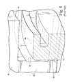
- the supplemental seal generally designated 70, includes a seal body 72 preferably formed of sheet metal having a first margin 74 for engaging within a groove 76 ( Figure 7) formed along a radial inner surface 73 of the inner rail 52 of each segment.
- Seal 70 also includes a second margin 78 along an opposite side thereof for engaging the sealing surface 54 of the nozzle support ring 44. As illustrated in Figure 5, the supplemental seal 70 lies radially inwardly of the chordal hinge seal 46, including the projection 48, and thus seals between the high pressure region 37 and the downstream region on the opposite side of the seal, including the chordal hinge seal.
- the supplemental seal 70 is provided in segments corresponding to the number of nozzle segments.
- the first margin of the supplemental seal extends in a chord-wise direction for insertion within the linear groove 76 of the inner rail 52.
- the inner margin 74 of supplemental seal 70 includes an edge 80 ( Figure 7) which is bent or folded over to bear against a surface of the groove 76, preferably the base of the groove, to seal against passage of a fluid, e.g., air, from one side of the seal to the opposite side along the groove.
- At least one elongated strip of metal 82 is secured, for example, by welding, along one side of the first margin 74 of the sheet metal seal 70.
- the elongated strip includes a flange 84 which cooperates with the flange 75 formed in the groove 76 to retain the first margin 74 of the supplemental seal within the groove 76.
- an elongated metal strip 86 is likewise secured along the opposite side of the margin from the first strip 82, thus locating the margin 74 of the flexible sheet metal seal essentially within the linear groove 76.
- the opposite or second arcuate margin 78 of the supplemental seal bears against the annular sealing surface 54 of the nozzle support ring 44.
- the second margin 78 extends arcuately about the axis of the rotor.
- the supplemental seal 70 is preloaded or biased such that the second margin 78 bears against the sealing surface 54 of the nozzle support ring 44.
- the sheet metal seal 70 is also biased into engagement with the nozzle support ring due to the pressure difference on opposite sides of the seal 70.
- the supplemental flexible seal 70 lies radially inboard of the chordal hinge seal 46 and extends between the chord-wise extending, radially innermost surface of the inner rail 52 and the annular sealing surface 54 of the nozzle support ring 44.
- any leakage flow past the supplemental seal 70 encounters the chordal hinge seal 46 at a lower pressure.
- the supplemental seal 70 is provided for each nozzle segment. The adjacent ends of seals 70 formed on adjacent nozzles may overlap one another, however, providing effective inter-segment supplemental seals at the joint between adjacent segment.
Landscapes
- Engineering & Computer Science (AREA)
- General Engineering & Computer Science (AREA)
- Mechanical Engineering (AREA)
- Turbine Rotor Nozzle Sealing (AREA)
- Gasket Seals (AREA)
Abstract
Description
vane (20) and an inner rail (52), said inner rails of said segments forming a generally annular second surface (50) in axial opposition to said first surface, each of said segments including an axially extending projection (48) along said second surface thereof for engagement with said first surface to form a first seal (46) therebetween sealing between high and low pressure regions on opposite sides of the seal;
a plurality of flexible supplemental seal segments (70) extending between said inner rails (52) and said first surface (54) at locations radially inwardly of said first seal, each flexible seal segment having a first margin (74) secured to the inner rails of at least two adjoining segments and spanning at least the joint therebetween, a second margin (78) of each said flexible seal segment sealingly engageable with said first surface in response to leakage flow past said first seal.
Claims (10)
- A turbine comprising:a turbine nozzle support ring (44) having a generally axially facing first surface (52);a turbine nozzle segment having at least one stator vane (20) and including an inner band (38) carrying an inner rail (52), said inner rail having a second surface (50) in axial opposition to said first surface;one of said first and second surfaces including an axially extending projection (48) therealong for engagement with another of said first and second surfaces to form a first seal (46) therebetween sealing between high and low pressure regions (37, 14) on opposite sides of said seal; anda flexible supplemental seal (70) extending between said inner rail (52) and said first surface at a location radially inwardly of said first seal and between at least opposite end edges of said segment, a first margin (74) of said flexible seal being secured to said inner rail and a second margin (78) of said flexible seal sealingly engageable with said first surface.
- A turbine according to Claim 1 wherein said second margin (78) of said flexible seal is arcuate in a circumferential direction about an axis of the turbine.
- A turbine according to Claim 1 or 2 wherein said flexible seal comprises sheet metal.
- A turbine according to Claim 1, 2 or 3 including a groove (76) formed in said inner rail, said flexible seal being formed of sheet metal and said first margin (74) of said flexible seal including an edge (80) of said sheet metal bent to sealingly engage a surface of said groove.
- A turbine according to Claim 1, 2 or 3 including a groove (76) formed in said inner rail (52), said flexible seal (70) being formed of sheet metal, an elongated first strip (82) secured to said flexible seal along said first margin thereof and engaging within said groove to retain said flexible seal in said groove.
- A turbine according to any preceding Claim wherein said flexible seal is preloaded to sealingly engage said first surface.
- A gas turbine comprising:a plurality of turbine nozzle segments (41) each having at least one statora turbine nozzle support ring (44) having a generally axially facing first surface (54);
vane (20) and an inner rail (52), said inner rails of said segments forming a generally annular second surface (50) in axial opposition to said first surface, each of said segments including an axially extending projection (48) along said second surface thereof for engagement with said first surface to form a first seal (46) therebetween sealing between high and low pressure regions on opposite sides of the seal;
a plurality of flexible supplemental seal segments (70) extending between said inner rails (52) and said first surface (54) at locations radially inwardly of said first seal, each flexible seal segment having a first margin (74) secured to the inner rails of at least two adjoining segments and spanning at least the joint therebetween, a second margin (78) of each said flexible seal segment sealingly engageable with said first surface in response to leakage flow past said first seal. - A turbine according to Claim 7 wherein said axially extending projection (48) along each of said nozzle segments extends along a chord line of each said segment.
- A turbine according to Claim 8 wherein said first margins (74) of said flexible seal segments form an annulus about an axis of the turbine.
- A turbine according to Claim 7, 8 or 9 wherein said flexible seal is preloaded to sealingly engage said first surface.
Applications Claiming Priority (2)
| Application Number | Priority Date | Filing Date | Title |
|---|---|---|---|
| US10/028,924 US6641144B2 (en) | 2001-12-28 | 2001-12-28 | Supplemental seal for the chordal hinge seals in a gas turbine |
| US28924 | 2001-12-28 |
Publications (3)
| Publication Number | Publication Date |
|---|---|
| EP1323891A2 true EP1323891A2 (en) | 2003-07-02 |
| EP1323891A3 EP1323891A3 (en) | 2004-05-26 |
| EP1323891B1 EP1323891B1 (en) | 2007-03-14 |
Family
ID=21846253
Family Applications (1)
| Application Number | Title | Priority Date | Filing Date |
|---|---|---|---|
| EP02258830A Expired - Lifetime EP1323891B1 (en) | 2001-12-28 | 2002-12-23 | Supplemental seal for the chordal hinge seals in a gas turbine |
Country Status (5)
| Country | Link |
|---|---|
| US (1) | US6641144B2 (en) |
| EP (1) | EP1323891B1 (en) |
| JP (1) | JP4248871B2 (en) |
| KR (1) | KR100747837B1 (en) |
| DE (1) | DE60218808T2 (en) |
Cited By (2)
| Publication number | Priority date | Publication date | Assignee | Title |
|---|---|---|---|---|
| EP1323897A3 (en) * | 2001-12-28 | 2004-04-14 | General Electric Company | Supplemental seal for the chordal hinge seals in a gas turbine |
| EP1515003A1 (en) * | 2003-09-11 | 2005-03-16 | Siemens Aktiengesellschaft | Gas turbine and sealing means for a gas turbine |
Families Citing this family (10)
| Publication number | Priority date | Publication date | Assignee | Title |
|---|---|---|---|---|
| US7094026B2 (en) * | 2004-04-29 | 2006-08-22 | General Electric Company | System for sealing an inner retainer segment and support ring in a gas turbine and methods therefor |
| WO2006036834A2 (en) * | 2004-09-24 | 2006-04-06 | Amgen Inc. | MODIFIED Fc MOLECULES |
| US7625174B2 (en) * | 2005-12-16 | 2009-12-01 | General Electric Company | Methods and apparatus for assembling gas turbine engine stator assemblies |
| US7793507B2 (en) * | 2006-09-07 | 2010-09-14 | General Electric Company | Expansion joint for gas turbines |
| EP2180143A1 (en) | 2008-10-23 | 2010-04-28 | Siemens Aktiengesellschaft | Gas turbine nozzle arrangement and gas turbine |
| EP2187002A1 (en) | 2008-11-12 | 2010-05-19 | Siemens Aktiengesellschaft | Gas turbine nozzle arrangement and gas turbine |
| US9482107B2 (en) | 2009-09-28 | 2016-11-01 | Siemens Aktiengesellschaft | Gas turbine nozzle arrangement and gas turbine |
| US20110164965A1 (en) * | 2010-01-06 | 2011-07-07 | General Electric Company | Steam turbine stationary component seal |
| US10519807B2 (en) | 2017-04-19 | 2019-12-31 | Rolls-Royce Corporation | Seal segment retention ring with chordal seal feature |
| JP7565690B2 (en) * | 2020-02-07 | 2024-10-11 | 三菱重工コンプレッサ株式会社 | Compressor manufacturing method and compressor |
Family Cites Families (23)
| Publication number | Priority date | Publication date | Assignee | Title |
|---|---|---|---|---|
| US2609176A (en) * | 1950-01-21 | 1952-09-02 | A V Roe Canada Ltd | Turbine nozzle guide vane construction |
| US4184689A (en) | 1978-10-02 | 1980-01-22 | United Technologies Corporation | Seal structure for an axial flow rotary machine |
| US4314793A (en) * | 1978-12-20 | 1982-02-09 | United Technologies Corporation | Temperature actuated turbine seal |
| US4645217A (en) * | 1985-11-29 | 1987-02-24 | United Technologies Corporation | Finger seal assembly |
| US4883405A (en) * | 1987-11-13 | 1989-11-28 | The United States Of America As Represented By The Secretary Of The Air Force | Turbine nozzle mounting arrangement |
| US4815933A (en) | 1987-11-13 | 1989-03-28 | The United States Of America As Represented By The Secretary Of The Air Force | Nozzle flange attachment and sealing arrangement |
| US5118120A (en) * | 1989-07-10 | 1992-06-02 | General Electric Company | Leaf seals |
| US5149250A (en) | 1991-02-28 | 1992-09-22 | General Electric Company | Gas turbine vane assembly seal and support system |
| US5143292A (en) * | 1991-05-09 | 1992-09-01 | General Electric Company | Cooled leaf seal |
| US5271714A (en) | 1992-07-09 | 1993-12-21 | General Electric Company | Turbine nozzle support arrangement |
| US5372476A (en) | 1993-06-18 | 1994-12-13 | General Electric Company | Turbine nozzle support assembly |
| FR2728016B1 (en) * | 1994-12-07 | 1997-01-17 | Snecma | NON-SECTORIZED MONOBLOCK DISTRIBUTOR OF A TURBOMACHINE TURBINE STATOR |
| US5653580A (en) * | 1995-03-06 | 1997-08-05 | Solar Turbines Incorporated | Nozzle and shroud assembly mounting structure |
| US5509669A (en) * | 1995-06-19 | 1996-04-23 | General Electric Company | Gas-path leakage seal for a gas turbine |
| US5797723A (en) * | 1996-11-13 | 1998-08-25 | General Electric Company | Turbine flowpath seal |
| US6076835A (en) * | 1997-05-21 | 2000-06-20 | Allison Advanced Development Company | Interstage van seal apparatus |
| US5915697A (en) | 1997-09-22 | 1999-06-29 | General Electric Company | Flexible cloth seal assembly |
| US6065756A (en) * | 1997-12-10 | 2000-05-23 | General Electric Co. | Flex seal for gas turbine expansion joints |
| FR2786222B1 (en) * | 1998-11-19 | 2000-12-29 | Snecma | LAMELLE SEALING DEVICE |
| US6095750A (en) | 1998-12-21 | 2000-08-01 | General Electric Company | Turbine nozzle assembly |
| US6435820B1 (en) * | 1999-08-25 | 2002-08-20 | General Electric Company | Shroud assembly having C-clip retainer |
| US6572331B1 (en) * | 2001-12-28 | 2003-06-03 | General Electric Company | Supplemental seal for the chordal hinge seals in a gas turbine |
| US6595745B1 (en) * | 2001-12-28 | 2003-07-22 | General Electric Company | Supplemental seal for the chordal hinge seals in a gas turbine |
-
2001
- 2001-12-28 US US10/028,924 patent/US6641144B2/en not_active Expired - Fee Related
-
2002
- 2002-12-23 DE DE60218808T patent/DE60218808T2/en not_active Expired - Lifetime
- 2002-12-23 EP EP02258830A patent/EP1323891B1/en not_active Expired - Lifetime
- 2002-12-26 JP JP2002376194A patent/JP4248871B2/en not_active Expired - Fee Related
- 2002-12-27 KR KR1020020084890A patent/KR100747837B1/en not_active Expired - Fee Related
Cited By (5)
| Publication number | Priority date | Publication date | Assignee | Title |
|---|---|---|---|---|
| EP1323897A3 (en) * | 2001-12-28 | 2004-04-14 | General Electric Company | Supplemental seal for the chordal hinge seals in a gas turbine |
| EP1515003A1 (en) * | 2003-09-11 | 2005-03-16 | Siemens Aktiengesellschaft | Gas turbine and sealing means for a gas turbine |
| WO2005026502A1 (en) * | 2003-09-11 | 2005-03-24 | Siemens Aktiengesellschaft | Gas turbine and sealing means for a gas turbine |
| CN100467832C (en) * | 2003-09-11 | 2009-03-11 | 西门子公司 | gas turbine |
| US7530233B2 (en) | 2003-09-11 | 2009-05-12 | Siemens Aktiengesellschaft | Gas turbine and sealing means for a gas turbine |
Also Published As
| Publication number | Publication date |
|---|---|
| KR20030057421A (en) | 2003-07-04 |
| EP1323891A3 (en) | 2004-05-26 |
| DE60218808T2 (en) | 2007-12-06 |
| KR100747837B1 (en) | 2007-08-08 |
| JP2003227352A (en) | 2003-08-15 |
| JP4248871B2 (en) | 2009-04-02 |
| EP1323891B1 (en) | 2007-03-14 |
| DE60218808D1 (en) | 2007-04-26 |
| US6641144B2 (en) | 2003-11-04 |
| US20030122320A1 (en) | 2003-07-03 |
Similar Documents
| Publication | Publication Date | Title |
|---|---|---|
| US6637751B2 (en) | Supplemental seal for the chordal hinge seals in a gas turbine | |
| US6637752B2 (en) | Supplemental seal for the chordal hinge seal in a gas turbine | |
| EP1323899B1 (en) | Gasturbine with a supplemental seal for the chordal hinge seal | |
| US6609885B2 (en) | Supplemental seal for the chordal hinge seal in a gas turbine | |
| EP1323894B1 (en) | Supplemental seal for the chordal hinge seals in a gas turbine | |
| US6599089B2 (en) | Supplemental seal for the chordal hinge seal in a gas turbine | |
| US6572331B1 (en) | Supplemental seal for the chordal hinge seals in a gas turbine | |
| US6641144B2 (en) | Supplemental seal for the chordal hinge seals in a gas turbine | |
| US6637753B2 (en) | Supplemental seal for the chordal hinge seals in a gas turbine | |
| US6568903B1 (en) | Supplemental seal for the chordal hinge seals in a gas turbine | |
| EP1323897B1 (en) | Turbine with a supplemental seal for the chordal hinge sealing |
Legal Events
| Date | Code | Title | Description |
|---|---|---|---|
| PUAI | Public reference made under article 153(3) epc to a published international application that has entered the european phase |
Free format text: ORIGINAL CODE: 0009012 |
|
| AK | Designated contracting states |
Designated state(s): AT BE BG CH CY CZ DE DK EE ES FI FR GB GR IE IT LI LU MC NL PT SE SI SK TR |
|
| AX | Request for extension of the european patent |
Extension state: AL LT LV MK RO |
|
| RIN1 | Information on inventor provided before grant (corrected) |
Inventor name: FANG, NING Inventor name: SAFI, AHMAD Inventor name: AKSIT, MAHMUT FARUK Inventor name: MOHAMMED-FAKIR, ABDUL-AZEEZ Inventor name: VEDANTAM, SRIKANTH |
|
| PUAL | Search report despatched |
Free format text: ORIGINAL CODE: 0009013 |
|
| AK | Designated contracting states |
Kind code of ref document: A3 Designated state(s): AT BE BG CH CY CZ DE DK EE ES FI FR GB GR IE IT LI LU MC NL PT SE SI SK TR |
|
| AX | Request for extension of the european patent |
Extension state: AL LT LV MK RO |
|
| 17P | Request for examination filed |
Effective date: 20041126 |
|
| AKX | Designation fees paid |
Designated state(s): CH DE FR GB IT LI |
|
| 17Q | First examination report despatched |
Effective date: 20050527 |
|
| GRAP | Despatch of communication of intention to grant a patent |
Free format text: ORIGINAL CODE: EPIDOSNIGR1 |
|
| GRAS | Grant fee paid |
Free format text: ORIGINAL CODE: EPIDOSNIGR3 |
|
| GRAA | (expected) grant |
Free format text: ORIGINAL CODE: 0009210 |
|
| AK | Designated contracting states |
Kind code of ref document: B1 Designated state(s): CH DE FR GB IT LI |
|
| REG | Reference to a national code |
Ref country code: GB Ref legal event code: FG4D |
|
| REG | Reference to a national code |
Ref country code: CH Ref legal event code: EP Ref country code: CH Ref legal event code: NV Representative=s name: SERVOPATENT GMBH |
|
| REF | Corresponds to: |
Ref document number: 60218808 Country of ref document: DE Date of ref document: 20070426 Kind code of ref document: P |
|
| RIN2 | Information on inventor provided after grant (corrected) |
Inventor name: SAFI, AHMAD Inventor name: AKSIT, MAHMUT FARUK Inventor name: MOHAMMED-FAKIR, ABDUL-AZEEZ Inventor name: VEDANTAM, SRIKANTH Inventor name: FANG, NING |
|
| ET | Fr: translation filed | ||
| PLBE | No opposition filed within time limit |
Free format text: ORIGINAL CODE: 0009261 |
|
| STAA | Information on the status of an ep patent application or granted ep patent |
Free format text: STATUS: NO OPPOSITION FILED WITHIN TIME LIMIT |
|
| REG | Reference to a national code |
Ref country code: CH Ref legal event code: PFA Owner name: GENERAL ELECTRIC COMPANY Free format text: GENERAL ELECTRIC COMPANY#1 RIVER ROAD#SCHENECTADY, NY 12345 (US) -TRANSFER TO- GENERAL ELECTRIC COMPANY#1 RIVER ROAD#SCHENECTADY, NY 12345 (US) |
|
| 26N | No opposition filed |
Effective date: 20071217 |
|
| PGFP | Annual fee paid to national office [announced via postgrant information from national office to epo] |
Ref country code: CH Payment date: 20141229 Year of fee payment: 13 Ref country code: GB Payment date: 20141229 Year of fee payment: 13 |
|
| PGFP | Annual fee paid to national office [announced via postgrant information from national office to epo] |
Ref country code: FR Payment date: 20141217 Year of fee payment: 13 |
|
| PGFP | Annual fee paid to national office [announced via postgrant information from national office to epo] |
Ref country code: DE Payment date: 20141230 Year of fee payment: 13 Ref country code: IT Payment date: 20141224 Year of fee payment: 13 |
|
| REG | Reference to a national code |
Ref country code: DE Ref legal event code: R119 Ref document number: 60218808 Country of ref document: DE |
|
| REG | Reference to a national code |
Ref country code: CH Ref legal event code: PL |
|
| GBPC | Gb: european patent ceased through non-payment of renewal fee |
Effective date: 20151223 |
|
| REG | Reference to a national code |
Ref country code: FR Ref legal event code: ST Effective date: 20160831 |
|
| PG25 | Lapsed in a contracting state [announced via postgrant information from national office to epo] |
Ref country code: DE Free format text: LAPSE BECAUSE OF NON-PAYMENT OF DUE FEES Effective date: 20160701 Ref country code: GB Free format text: LAPSE BECAUSE OF NON-PAYMENT OF DUE FEES Effective date: 20151223 Ref country code: LI Free format text: LAPSE BECAUSE OF NON-PAYMENT OF DUE FEES Effective date: 20151231 Ref country code: CH Free format text: LAPSE BECAUSE OF NON-PAYMENT OF DUE FEES Effective date: 20151231 |
|
| PG25 | Lapsed in a contracting state [announced via postgrant information from national office to epo] |
Ref country code: FR Free format text: LAPSE BECAUSE OF NON-PAYMENT OF DUE FEES Effective date: 20151231 |
|
| PG25 | Lapsed in a contracting state [announced via postgrant information from national office to epo] |
Ref country code: IT Free format text: LAPSE BECAUSE OF NON-PAYMENT OF DUE FEES Effective date: 20151223 |