EP1323618A1 - Ensemble de direction de véhicule - Google Patents
Ensemble de direction de véhicule Download PDFInfo
- Publication number
- EP1323618A1 EP1323618A1 EP02293140A EP02293140A EP1323618A1 EP 1323618 A1 EP1323618 A1 EP 1323618A1 EP 02293140 A EP02293140 A EP 02293140A EP 02293140 A EP02293140 A EP 02293140A EP 1323618 A1 EP1323618 A1 EP 1323618A1
- Authority
- EP
- European Patent Office
- Prior art keywords
- hub
- steering wheel
- steering
- assembly according
- flywheel
- Prior art date
- Legal status (The legal status is an assumption and is not a legal conclusion. Google has not performed a legal analysis and makes no representation as to the accuracy of the status listed.)
- Granted
Links
- 238000010586 diagram Methods 0.000 description 2
- 239000004020 conductor Substances 0.000 description 1
- 238000010276 construction Methods 0.000 description 1
- 230000004048 modification Effects 0.000 description 1
- 238000012986 modification Methods 0.000 description 1
Images


Classifications
-
- B—PERFORMING OPERATIONS; TRANSPORTING
- B60—VEHICLES IN GENERAL
- B60R—VEHICLES, VEHICLE FITTINGS, OR VEHICLE PARTS, NOT OTHERWISE PROVIDED FOR
- B60R21/00—Arrangements or fittings on vehicles for protecting or preventing injuries to occupants or pedestrians in case of accidents or other traffic risks
- B60R21/02—Occupant safety arrangements or fittings, e.g. crash pads
- B60R21/16—Inflatable occupant restraints or confinements designed to inflate upon impact or impending impact, e.g. air bags
- B60R21/20—Arrangements for storing inflatable members in their non-use or deflated condition; Arrangement or mounting of air bag modules or components
- B60R21/203—Arrangements for storing inflatable members in their non-use or deflated condition; Arrangement or mounting of air bag modules or components in steering wheels or steering columns
- B60R21/2032—Arrangements for storing inflatable members in their non-use or deflated condition; Arrangement or mounting of air bag modules or components in steering wheels or steering columns the inflator or inflatable member not being rotatable with the steering wheel; Arrangements using the steering column or steering wheel rim for storing, supplying or evacuating the inflation gas or for storing the inflatable member
-
- B—PERFORMING OPERATIONS; TRANSPORTING
- B62—LAND VEHICLES FOR TRAVELLING OTHERWISE THAN ON RAILS
- B62D—MOTOR VEHICLES; TRAILERS
- B62D1/00—Steering controls, i.e. means for initiating a change of direction of the vehicle
- B62D1/02—Steering controls, i.e. means for initiating a change of direction of the vehicle vehicle-mounted
- B62D1/04—Hand wheels
-
- B—PERFORMING OPERATIONS; TRANSPORTING
- B62—LAND VEHICLES FOR TRAVELLING OTHERWISE THAN ON RAILS
- B62D—MOTOR VEHICLES; TRAILERS
- B62D1/00—Steering controls, i.e. means for initiating a change of direction of the vehicle
- B62D1/02—Steering controls, i.e. means for initiating a change of direction of the vehicle vehicle-mounted
- B62D1/04—Hand wheels
- B62D1/10—Hubs; Connecting hubs to steering columns, e.g. adjustable
- B62D1/105—Non-rotatable hubs, e.g. the central part of the steering wheel not rotating
Definitions
- the present invention relates to a steering assembly of a vehicle.
- a vehicle steering assembly more specifically of a car, includes a steering column with one end of which is mounted fixes a steering wheel.
- the steering wheel includes a central hub around which is arranged a ring intended to be held by the driver.
- the central hub is typically provided with controls, for example switches, intended to be actuated manually by the driver.
- the central hub of the steering wheel can also be fitted with a system such as an airbag, more commonly known as an "air bag”.
- a system such as an airbag, more commonly known as an "air bag”.
- the applicant has set itself the objective of overcoming the difficulties and the drawbacks encountered in the prior art by proposing a steering assembly which ensures that the controls arranged on the steering wheel hub are always within reach of the driver, regardless of the angle of the steering wheel, which allows you to ride an airbag of optimal shape.
- the present invention relates to a steering assembly of a vehicle comprising a steering column at one end of which is mounted fixed a flywheel and a hub adjacent to the flywheel but free in rotation relative thereto and comprising functional means characterized in that the assembly further comprises means for put the hub in rotation with the steering column and arranged, when a rotation of the flywheel, to rotate the hub in the same direction that the steering wheel to a predetermined angle thereof, a rotation of the flying beyond the predetermined angle not causing rotation additional hub.
- the means for rotating the hub are mounted on the steering wheel.
- the steering wheel and the hub have a rest position common, the means to rotate the hub with the column being arranged, when the steering wheel rotates beyond the angle predetermined, to return the hub to its rest position.
- the functional means comprise a bag inflatable safety or controls.
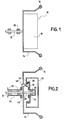
- FIG. 1 is shown schematically a set of direction 10 of conventional construction.
- This set includes a steering column 12 at one end of which is mounted fixed a steering wheel 14 formed of a ring 16, intended to be held by a conductor, arranged around a hub 18.
- the column is free to rotate relative to to the structure of the vehicle (not shown) by means of the bearings 20.
- the hub 18 is provided with an airbag which, so that it can act so safe whatever the angle of the steering wheel, has a symmetrical shape with respect to its center.
- FIG. 2 shows the steering assembly according to the invention.
- the elements of this set that are common with all of the Figure 1 bear the same reference numbers. Fixed elements are represented by dotted lines.
- the steering column 12 mounted on the structure 26 of the vehicle by means of bearings 20, has an extension 30 projecting inside the steering wheel 14 and provided with a bearing 32.
- the hub 18 is mounted on the extension 30 by means of the bearing 32 which makes it free to rotate relative to the steering wheel 14.
- the bottom 34 of the hub 18 disposed towards the inside of the flywheel 14 is formed with a crown 36 arranged to cooperate with a pinion 38 disposed on a servo motor 40 which is mounted on the flywheel 14.
- a rotation of the servo motor causes a rotation relative between the hub 18 and the flywheel 14.
- the hub when the steering wheel is rotated in one direction, the hub is also rotated in the same direction and at the same speed as the flywheel, until the hub reaches a predetermined angle to the rest position of the assembly of direction.
- the hub is then held in this position regardless of the angle taken by the steering wheel beyond this angle.
- the angle predetermined is 30 °, but this angle can be between 10 and 45 ° about.
- the hub when the flywheel is rotated beyond the predetermined angle, the hub follows the movement of the steering wheel to the predetermined angle, then starts to turn in the opposite direction to return to its rest position, and what that the angle of the steering wheel beyond the predetermined angle.
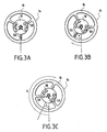
- FIG 3 illustrates the operation of the first embodiment of the invention.
- the flywheel 14 and the hub 18 in their common rest position.
- the steering wheel has three arms 50.
- Figure 3b illustrates the flywheel and hub in a common position when the flywheel has been turned through an angle a that is equal to or less than the predetermined angle.
- the servo motor 40 controlled by the computer, rotates the hub 18 at the same time, and through the same angle, as the flywheel so as to compensate for the movement of the flywheel relative to the hub.
- Figure 3c is shown the flywheel 14 after having been rotated through an angle b greater than the predetermined angle.
- the hub 18 is maintained by the servo motor at the predetermined angle c relative to its rest position, despite the angle taken beyond by the steering wheel. In this position the controls arranged on the hub 18 are always within reach of the driver's fingers and the airbag remains in an optimal position.
- Figure 4 illustrates the operation of the second embodiment of the invention.
- Figure 4a are shown the flywheel 14 and the hub 18 in their common rest position.
- Figure 4b illustrates the flywheel and the hub in a common position, that is, when the flywheel has been turned through an angle a that is equal to or less than the predetermined angle.
- the servo motor 40 controlled by the computer, forces the hub 18 to turn at the same time, and through the same angle, as the flywheel.
- Figure 4c is shown the flywheel 14 after being rotated through an angle b greater than the predetermined angle.
- the hub 18 is slowly repositioned in its rest position by the servo motor, a position it will keep until the flywheel returns to its own rest position.
- the controls arranged on the hub 18 are always within reach of the driver's fingers and the airbag remains in an optimal position.
- the hub can be rotated by report to the steering wheel by an electric motor connected to a passing belt around the hub, or by gears.
- Figure 5 is a flow diagram illustrating the relationship between components of the steering assembly according to the invention.
- the hub When the steering wheel is turned beyond the predetermined angle, the hub is kept stationary.
- the rotation of the steering wheel arms is detected by the column sensor which measures 1 angle between the column and the structure 26 of the vehicle.
- this angle is greater than the angle predetermined electronic module blocks motor rotation servo 41 so that the hub is fixed.
- the flying angle reduced below the predetermined angle the device returns to the previous mode.
- the present invention provides a steering assembly requiring little modifications to the steering wheel and hub structure, but which ensures that the control keys are always at the fingertips of the driver and allows to offer an optimal shape to the airbag of security. In addition, it offers free form to the hub and steering wheel.
Landscapes
- Engineering & Computer Science (AREA)
- Mechanical Engineering (AREA)
- Chemical & Material Sciences (AREA)
- Combustion & Propulsion (AREA)
- Transportation (AREA)
- Air Bags (AREA)
- Steering-Linkage Mechanisms And Four-Wheel Steering (AREA)
- Power Steering Mechanism (AREA)
- Automatic Assembly (AREA)
- Steering Controls (AREA)
Abstract
Description
- la Figure 1 est une section schématique d'un ensemble de direction selon l'art antérieur;
- la Figure 2 est une section schématique d'un ensemble de direction selon l'invention;
- les Figures 3a, 3b et 3c sont chacune une vue schématique d'un ensemble de volant selon un premier mode de réalisation de l'invention;
- les Figures 4a, 4b et 4c sont chacune une vue schématique d'un ensemble de volant selon un deuxième mode de réalisation de l'invention ; et
- la figure 5 est un logigramme illustrant des moyens permettant la mise en oeuvre de l'invention.
Claims (8)
- Ensemble de direction d'un véhicule comprenant une colonne de direction à une extrémité de laquelle est monté fixé un volant et un moyeu adjacent au volant mais libre en rotation par rapport à celui-ci et comprenant des moyens fonctionnels caractérisé en ce que l'ensemble comprend de plus des moyens pour mettre le moyeu en rotation avec la colonne de direction et agencés, lors d'une rotation du volant, pour faire tourner le moyeu dans le même sens que le volant jusqu'à un angle prédéterminé de celui-ci, une rotation du volant au delà de l'angle prédéterminé ne provoquant pas de rotation additionnel du moyeu.
- Ensemble selon la revendication 1 caractérisé en ce que les moyens pour mettre le moyeu en rotation sont montés sur le volant.
- Ensemble selon la revendication 1 caractérisé en ce que les moyens pour mettre le moyeu en rotation sont montés sur le moyeu.
- Ensemble selon l'une des revendication 1 à 3 caractérisé en ce que le volant et le moyeu ont une position de repos commune, les moyens pour mettre le moyeu en rotation avec la colonne de direction étant agencés, lors d'une rotation du volant au delà de l'angle prédéterminé, pour faire revenir le moyeu vers sa position de repos.
- Ensemble selon l'une des revendication 1 à 3 caractérisé en ce que les moyens pour mettre le moyeu en rotation avec la colonne de direction comprennent un ensemble de pignons.
- Ensemble selon la revendication 5 caractérisé en ce que l'ensemble comprend de plus un capteur de la position angulaire du volant ainsi qu' un capteur de la position angulaire du moyeu.
- Ensemble selon l'une des revendication 1 à 6 caractérisé en ce que les moyens fonctionnels comprennent un sac gonflable de sécurité ou des commandes.
- Ensemble selon l'une des revendication précédentes caractérisé en ce que les moyens pour mettre le moyeu en rotation comprennent un moteur électrique.
Applications Claiming Priority (2)
| Application Number | Priority Date | Filing Date | Title |
|---|---|---|---|
| FR0116515 | 2001-12-20 | ||
| FR0116515A FR2833915B1 (fr) | 2001-12-20 | 2001-12-20 | Ensemble de direction de vehicule |
Publications (2)
| Publication Number | Publication Date |
|---|---|
| EP1323618A1 true EP1323618A1 (fr) | 2003-07-02 |
| EP1323618B1 EP1323618B1 (fr) | 2004-10-06 |
Family
ID=8870721
Family Applications (1)
| Application Number | Title | Priority Date | Filing Date |
|---|---|---|---|
| EP02293140A Expired - Lifetime EP1323618B1 (fr) | 2001-12-20 | 2002-12-18 | Ensemble de direction de véhicule |
Country Status (5)
| Country | Link |
|---|---|
| EP (1) | EP1323618B1 (fr) |
| AT (1) | ATE278594T1 (fr) |
| DE (1) | DE60201489T2 (fr) |
| ES (1) | ES2225741T3 (fr) |
| FR (1) | FR2833915B1 (fr) |
Cited By (4)
| Publication number | Priority date | Publication date | Assignee | Title |
|---|---|---|---|---|
| WO2017130815A1 (fr) * | 2016-01-27 | 2017-08-03 | 株式会社東海理化電機製作所 | Dispositif de commande de direction |
| US9738243B2 (en) | 2015-11-06 | 2017-08-22 | Toyota Jidosha Kabushiki Kaisha | Airbag device for driver's seat |
| US10065594B2 (en) | 2015-11-18 | 2018-09-04 | Toyota Jidosha Kabushiki Kaisha | Airbag device and airbag fabrication method |
| WO2024017655A1 (fr) * | 2022-07-20 | 2024-01-25 | ZF Automotive Safety Germany GmbH | Volant |
Families Citing this family (4)
| Publication number | Priority date | Publication date | Assignee | Title |
|---|---|---|---|---|
| FR2907181B1 (fr) | 2006-10-12 | 2008-12-05 | Peugeot Citroen Automobiles Sa | Procede de realisation d'un ressort helicoidal, un ressort helicoidal obtenu par la mise en oeuvre de ce procede, ainsi qu'un ensemble de direction comportant un tel ressort |
| DE102012017680B4 (de) * | 2012-09-07 | 2021-03-04 | Volkswagen Aktiengesellschaft | Verfahren zum Auslösen eines Airbags für ein Fahrzeug sowie entsprechend ausgestaltetes Sicherheitssystem |
| DE102015004745B4 (de) | 2015-04-11 | 2019-10-10 | Audi Ag | Verfahren zum Betreiben eines Kraftfahrzeugs und zugehöriges Kraftfahrzeug |
| EP4253123A1 (fr) | 2022-04-01 | 2023-10-04 | Hopper Mobility GmbH | Dispositif de support d'information-divertissement pour véhicule |
Citations (2)
| Publication number | Priority date | Publication date | Assignee | Title |
|---|---|---|---|---|
| US4485371A (en) * | 1981-04-14 | 1984-11-27 | Aisin Seiki Kabushiki Kaisha | Steering wheel system |
| US4604912A (en) * | 1983-02-25 | 1986-08-12 | Toyoda Gosei Co., Ltd. | Steering wheel |
Family Cites Families (1)
| Publication number | Priority date | Publication date | Assignee | Title |
|---|---|---|---|---|
| JPS59118547A (ja) | 1982-12-24 | 1984-07-09 | Toyoda Gosei Co Ltd | ステアリングホイ−ル |
-
2001
- 2001-12-20 FR FR0116515A patent/FR2833915B1/fr not_active Expired - Fee Related
-
2002
- 2002-12-18 EP EP02293140A patent/EP1323618B1/fr not_active Expired - Lifetime
- 2002-12-18 DE DE60201489T patent/DE60201489T2/de not_active Expired - Fee Related
- 2002-12-18 AT AT02293140T patent/ATE278594T1/de not_active IP Right Cessation
- 2002-12-18 ES ES02293140T patent/ES2225741T3/es not_active Expired - Lifetime
Patent Citations (2)
| Publication number | Priority date | Publication date | Assignee | Title |
|---|---|---|---|---|
| US4485371A (en) * | 1981-04-14 | 1984-11-27 | Aisin Seiki Kabushiki Kaisha | Steering wheel system |
| US4604912A (en) * | 1983-02-25 | 1986-08-12 | Toyoda Gosei Co., Ltd. | Steering wheel |
Cited By (4)
| Publication number | Priority date | Publication date | Assignee | Title |
|---|---|---|---|---|
| US9738243B2 (en) | 2015-11-06 | 2017-08-22 | Toyota Jidosha Kabushiki Kaisha | Airbag device for driver's seat |
| US10065594B2 (en) | 2015-11-18 | 2018-09-04 | Toyota Jidosha Kabushiki Kaisha | Airbag device and airbag fabrication method |
| WO2017130815A1 (fr) * | 2016-01-27 | 2017-08-03 | 株式会社東海理化電機製作所 | Dispositif de commande de direction |
| WO2024017655A1 (fr) * | 2022-07-20 | 2024-01-25 | ZF Automotive Safety Germany GmbH | Volant |
Also Published As
| Publication number | Publication date |
|---|---|
| FR2833915B1 (fr) | 2004-02-13 |
| DE60201489T2 (de) | 2006-02-23 |
| ES2225741T3 (es) | 2005-03-16 |
| FR2833915A1 (fr) | 2003-06-27 |
| EP1323618B1 (fr) | 2004-10-06 |
| DE60201489D1 (de) | 2004-11-11 |
| ATE278594T1 (de) | 2004-10-15 |
Similar Documents
| Publication | Publication Date | Title |
|---|---|---|
| EP1323617B1 (fr) | Ensemble de direction pour véhicule automobile | |
| EP1323618B1 (fr) | Ensemble de direction de véhicule | |
| FR2495088A1 (fr) | Systeme de direction pour vehicules a quatre roues directrices comportant une commande des roues arriere en fonction du mouvement du vehicule | |
| FR2822945A1 (fr) | Procede pour determiner la position angulaire d'un vehicule | |
| WO2011023862A1 (fr) | Controle de trajectoire pour vehicule etroit a inclinaison asservie | |
| EP0615889B1 (fr) | Ensemble de colonne de direction notamment pour véhicule automobile | |
| EP1190935A1 (fr) | Ensemble de direction à coussin central fixe, coussin central et véhicule automobile correspondants | |
| FR2542674A1 (fr) | Systeme de controle de pression de pneumatique | |
| EP3571466B1 (fr) | Procédé et dispositif autonomes de détermination d'une assiette d'un véhicule automobile | |
| FR2459154A1 (fr) | Dispositif a inertie pour corriger exactement l'orientation d'un projecteur de vehicule automobile en compensant l'effet des deplacements dynamiques de la partie suspendue par rapport a la partie non suspendue du vehicule. | |
| FR2922848A1 (fr) | Systeme de restitution d'efforts sur un volant de direction d'un vehicule automobile et procede de commande d'un tel systeme. | |
| FR2699445A1 (fr) | Procédé pour le contrôle sur une meuleuse de l'adéquation, à une monture de lunettes, d'un verre à meuler. | |
| FR2547264A1 (fr) | Dispositif de retenue d'une des roues d'un vehicule a deux roues | |
| EP0606034B1 (fr) | Machine à meuler des lentilles ophtalmiques | |
| EP1169210B1 (fr) | Vehicule a pendularite variable guidee | |
| FR2798329A1 (fr) | Dispositif de commande associe au volant d'un vehicule automobile | |
| EP2755009B1 (fr) | Système de diagnostic de l'état structurel d'une unité de roulement d'un engin à roues. | |
| EP0706029B1 (fr) | Système gyroscopique pour missile en autorotation | |
| FR2880145A1 (fr) | Organe de commutation et dispositif de commande comportant un tel organe | |
| EP1186472B1 (fr) | Dispositif pour la commande automatique d'extinction d'indicateurs de changement de direction sur véhicule automobile | |
| FR2701314A1 (fr) | Variation de la vitesse de rotation de corps tournants. | |
| FR3109361A1 (fr) | Système de protection d’un utilisateur, ensemble et utilisation d’un tel système de protection | |
| FR2978942A1 (fr) | Procede et dispositif d'affichage pour vehicule, element de vehicule muni d'un tel dispositif et vehicule muni d'un tel element. | |
| EP1454802B1 (fr) | Coussin gonflable fixe sur volant | |
| FR2562865A1 (fr) | Engin nautique ou terrestre comportant des moyens de propulsion sous l'effet du vent |
Legal Events
| Date | Code | Title | Description |
|---|---|---|---|
| PUAI | Public reference made under article 153(3) epc to a published international application that has entered the european phase |
Free format text: ORIGINAL CODE: 0009012 |
|
| AK | Designated contracting states |
Designated state(s): AT BE BG CH CY CZ DE DK EE ES FI FR GB GR IE IT LI LU MC NL PT SE SI SK TR |
|
| AX | Request for extension of the european patent |
Extension state: AL LT LV MK RO |
|
| 17P | Request for examination filed |
Effective date: 20030929 |
|
| AKX | Designation fees paid |
Designated state(s): AT BE BG CH CY CZ DE DK EE ES FI FR GB GR IE IT LI LU MC NL PT SE SI SK TR |
|
| GRAP | Despatch of communication of intention to grant a patent |
Free format text: ORIGINAL CODE: EPIDOSNIGR1 |
|
| GRAS | Grant fee paid |
Free format text: ORIGINAL CODE: EPIDOSNIGR3 |
|
| GRAA | (expected) grant |
Free format text: ORIGINAL CODE: 0009210 |
|
| AK | Designated contracting states |
Kind code of ref document: B1 Designated state(s): AT BE BG CH CY CZ DE DK EE ES FI FR GB GR IE IT LI LU MC NL PT SE SI SK TR |
|
| PG25 | Lapsed in a contracting state [announced via postgrant information from national office to epo] |
Ref country code: SI Free format text: LAPSE BECAUSE OF FAILURE TO SUBMIT A TRANSLATION OF THE DESCRIPTION OR TO PAY THE FEE WITHIN THE PRESCRIBED TIME-LIMIT Effective date: 20041006 Ref country code: CY Free format text: LAPSE BECAUSE OF FAILURE TO SUBMIT A TRANSLATION OF THE DESCRIPTION OR TO PAY THE FEE WITHIN THE PRESCRIBED TIME-LIMIT Effective date: 20041006 Ref country code: SE Free format text: LAPSE BECAUSE OF FAILURE TO SUBMIT A TRANSLATION OF THE DESCRIPTION OR TO PAY THE FEE WITHIN THE PRESCRIBED TIME-LIMIT Effective date: 20041006 Ref country code: FI Free format text: LAPSE BECAUSE OF FAILURE TO SUBMIT A TRANSLATION OF THE DESCRIPTION OR TO PAY THE FEE WITHIN THE PRESCRIBED TIME-LIMIT Effective date: 20041006 Ref country code: EE Free format text: LAPSE BECAUSE OF FAILURE TO SUBMIT A TRANSLATION OF THE DESCRIPTION OR TO PAY THE FEE WITHIN THE PRESCRIBED TIME-LIMIT Effective date: 20041006 Ref country code: IE Free format text: LAPSE BECAUSE OF FAILURE TO SUBMIT A TRANSLATION OF THE DESCRIPTION OR TO PAY THE FEE WITHIN THE PRESCRIBED TIME-LIMIT Effective date: 20041006 Ref country code: CZ Free format text: LAPSE BECAUSE OF FAILURE TO SUBMIT A TRANSLATION OF THE DESCRIPTION OR TO PAY THE FEE WITHIN THE PRESCRIBED TIME-LIMIT Effective date: 20041006 Ref country code: TR Free format text: LAPSE BECAUSE OF FAILURE TO SUBMIT A TRANSLATION OF THE DESCRIPTION OR TO PAY THE FEE WITHIN THE PRESCRIBED TIME-LIMIT Effective date: 20041006 Ref country code: NL Free format text: LAPSE BECAUSE OF FAILURE TO SUBMIT A TRANSLATION OF THE DESCRIPTION OR TO PAY THE FEE WITHIN THE PRESCRIBED TIME-LIMIT Effective date: 20041006 Ref country code: AT Free format text: LAPSE BECAUSE OF FAILURE TO SUBMIT A TRANSLATION OF THE DESCRIPTION OR TO PAY THE FEE WITHIN THE PRESCRIBED TIME-LIMIT Effective date: 20041006 Ref country code: BG Free format text: LAPSE BECAUSE OF FAILURE TO SUBMIT A TRANSLATION OF THE DESCRIPTION OR TO PAY THE FEE WITHIN THE PRESCRIBED TIME-LIMIT Effective date: 20041006 Ref country code: SK Free format text: LAPSE BECAUSE OF FAILURE TO SUBMIT A TRANSLATION OF THE DESCRIPTION OR TO PAY THE FEE WITHIN THE PRESCRIBED TIME-LIMIT Effective date: 20041006 |
|
| REG | Reference to a national code |
Ref country code: GB Ref legal event code: FG4D Free format text: NOT ENGLISH |
|
| REG | Reference to a national code |
Ref country code: CH Ref legal event code: EP |
|
| GBT | Gb: translation of ep patent filed (gb section 77(6)(a)/1977) | ||
| REG | Reference to a national code |
Ref country code: IE Ref legal event code: FG4D Free format text: FRENCH |
|
| REF | Corresponds to: |
Ref document number: 60201489 Country of ref document: DE Date of ref document: 20041111 Kind code of ref document: P |
|
| PG25 | Lapsed in a contracting state [announced via postgrant information from national office to epo] |
Ref country code: LU Free format text: LAPSE BECAUSE OF NON-PAYMENT OF DUE FEES Effective date: 20041218 |
|
| PG25 | Lapsed in a contracting state [announced via postgrant information from national office to epo] |
Ref country code: BE Free format text: LAPSE BECAUSE OF NON-PAYMENT OF DUE FEES Effective date: 20041231 Ref country code: MC Free format text: LAPSE BECAUSE OF NON-PAYMENT OF DUE FEES Effective date: 20041231 |
|
| PG25 | Lapsed in a contracting state [announced via postgrant information from national office to epo] |
Ref country code: GR Free format text: LAPSE BECAUSE OF FAILURE TO SUBMIT A TRANSLATION OF THE DESCRIPTION OR TO PAY THE FEE WITHIN THE PRESCRIBED TIME-LIMIT Effective date: 20050106 Ref country code: DK Free format text: LAPSE BECAUSE OF FAILURE TO SUBMIT A TRANSLATION OF THE DESCRIPTION OR TO PAY THE FEE WITHIN THE PRESCRIBED TIME-LIMIT Effective date: 20050106 |
|
| REG | Reference to a national code |
Ref country code: ES Ref legal event code: FG2A Ref document number: 2225741 Country of ref document: ES Kind code of ref document: T3 |
|
| NLV1 | Nl: lapsed or annulled due to failure to fulfill the requirements of art. 29p and 29m of the patents act | ||
| REG | Reference to a national code |
Ref country code: IE Ref legal event code: FD4D |
|
| BERE | Be: lapsed |
Owner name: PEUGEOT CITROEN AUTOMOBILES Effective date: 20041231 |
|
| PLBE | No opposition filed within time limit |
Free format text: ORIGINAL CODE: 0009261 |
|
| STAA | Information on the status of an ep patent application or granted ep patent |
Free format text: STATUS: NO OPPOSITION FILED WITHIN TIME LIMIT |
|
| 26N | No opposition filed |
Effective date: 20050707 |
|
| PG25 | Lapsed in a contracting state [announced via postgrant information from national office to epo] |
Ref country code: CH Free format text: LAPSE BECAUSE OF NON-PAYMENT OF DUE FEES Effective date: 20061231 Ref country code: LI Free format text: LAPSE BECAUSE OF NON-PAYMENT OF DUE FEES Effective date: 20061231 |
|
| REG | Reference to a national code |
Ref country code: GB Ref legal event code: 746 Effective date: 20070117 |
|
| REG | Reference to a national code |
Ref country code: CH Ref legal event code: PL |
|
| BERE | Be: lapsed |
Owner name: *PEUGEOT CITROEN AUTOMOBILES Effective date: 20041231 |
|
| PG25 | Lapsed in a contracting state [announced via postgrant information from national office to epo] |
Ref country code: PT Free format text: LAPSE BECAUSE OF NON-PAYMENT OF DUE FEES Effective date: 20050306 |
|
| PGFP | Annual fee paid to national office [announced via postgrant information from national office to epo] |
Ref country code: ES Payment date: 20081209 Year of fee payment: 7 |
|
| PGFP | Annual fee paid to national office [announced via postgrant information from national office to epo] |
Ref country code: IT Payment date: 20081218 Year of fee payment: 7 |
|
| PGFP | Annual fee paid to national office [announced via postgrant information from national office to epo] |
Ref country code: DE Payment date: 20090102 Year of fee payment: 7 |
|
| PGFP | Annual fee paid to national office [announced via postgrant information from national office to epo] |
Ref country code: GB Payment date: 20081125 Year of fee payment: 7 |
|
| GBPC | Gb: european patent ceased through non-payment of renewal fee |
Effective date: 20091218 |
|
| PG25 | Lapsed in a contracting state [announced via postgrant information from national office to epo] |
Ref country code: DE Free format text: LAPSE BECAUSE OF NON-PAYMENT OF DUE FEES Effective date: 20100701 |
|
| PG25 | Lapsed in a contracting state [announced via postgrant information from national office to epo] |
Ref country code: GB Free format text: LAPSE BECAUSE OF NON-PAYMENT OF DUE FEES Effective date: 20091218 |
|
| REG | Reference to a national code |
Ref country code: ES Ref legal event code: FD2A Effective date: 20110323 |
|
| PG25 | Lapsed in a contracting state [announced via postgrant information from national office to epo] |
Ref country code: IT Free format text: LAPSE BECAUSE OF NON-PAYMENT OF DUE FEES Effective date: 20091218 |
|
| PG25 | Lapsed in a contracting state [announced via postgrant information from national office to epo] |
Ref country code: ES Free format text: LAPSE BECAUSE OF NON-PAYMENT OF DUE FEES Effective date: 20110310 |
|
| PG25 | Lapsed in a contracting state [announced via postgrant information from national office to epo] |
Ref country code: ES Free format text: LAPSE BECAUSE OF NON-PAYMENT OF DUE FEES Effective date: 20091219 |
|
| PGFP | Annual fee paid to national office [announced via postgrant information from national office to epo] |
Ref country code: FR Payment date: 20120119 Year of fee payment: 10 |
|
| REG | Reference to a national code |
Ref country code: FR Ref legal event code: ST Effective date: 20130830 |
|
| PG25 | Lapsed in a contracting state [announced via postgrant information from national office to epo] |
Ref country code: FR Free format text: LAPSE BECAUSE OF NON-PAYMENT OF DUE FEES Effective date: 20130102 |