EP1322903B1 - Dual-frequency millimeter wave and laser radiation receiver - Google Patents
Dual-frequency millimeter wave and laser radiation receiver Download PDFInfo
- Publication number
- EP1322903B1 EP1322903B1 EP00981527A EP00981527A EP1322903B1 EP 1322903 B1 EP1322903 B1 EP 1322903B1 EP 00981527 A EP00981527 A EP 00981527A EP 00981527 A EP00981527 A EP 00981527A EP 1322903 B1 EP1322903 B1 EP 1322903B1
- Authority
- EP
- European Patent Office
- Prior art keywords
- laser
- receiver
- millimeter wave
- reflector
- radiation
- Prior art date
- Legal status (The legal status is an assumption and is not a legal conclusion. Google has not performed a legal analysis and makes no representation as to the accuracy of the status listed.)
- Expired - Lifetime
Links
Images


Classifications
-
- F—MECHANICAL ENGINEERING; LIGHTING; HEATING; WEAPONS; BLASTING
- F41—WEAPONS
- F41G—WEAPON SIGHTS; AIMING
- F41G7/00—Direction control systems for self-propelled missiles
- F41G7/20—Direction control systems for self-propelled missiles based on continuous observation of target position
- F41G7/22—Homing guidance systems
- F41G7/226—Semi-active homing systems, i.e. comprising a receiver and involving auxiliary illuminating means, e.g. using auxiliary guiding missiles
-
- F—MECHANICAL ENGINEERING; LIGHTING; HEATING; WEAPONS; BLASTING
- F41—WEAPONS
- F41G—WEAPON SIGHTS; AIMING
- F41G7/00—Direction control systems for self-propelled missiles
- F41G7/008—Combinations of different guidance systems
-
- F—MECHANICAL ENGINEERING; LIGHTING; HEATING; WEAPONS; BLASTING
- F41—WEAPONS
- F41G—WEAPON SIGHTS; AIMING
- F41G7/00—Direction control systems for self-propelled missiles
- F41G7/20—Direction control systems for self-propelled missiles based on continuous observation of target position
- F41G7/22—Homing guidance systems
- F41G7/2273—Homing guidance systems characterised by the type of waves
- F41G7/2286—Homing guidance systems characterised by the type of waves using radio waves
-
- F—MECHANICAL ENGINEERING; LIGHTING; HEATING; WEAPONS; BLASTING
- F41—WEAPONS
- F41G—WEAPON SIGHTS; AIMING
- F41G7/00—Direction control systems for self-propelled missiles
- F41G7/20—Direction control systems for self-propelled missiles based on continuous observation of target position
- F41G7/22—Homing guidance systems
- F41G7/2273—Homing guidance systems characterised by the type of waves
- F41G7/2293—Homing guidance systems characterised by the type of waves using electromagnetic waves other than radio waves
-
- F—MECHANICAL ENGINEERING; LIGHTING; HEATING; WEAPONS; BLASTING
- F42—AMMUNITION; BLASTING
- F42B—EXPLOSIVE CHARGES, e.g. FOR BLASTING, FIREWORKS, AMMUNITION
- F42B30/00—Projectiles or missiles, not otherwise provided for, characterised by the ammunition class or type, e.g. by the launching apparatus or weapon used
- F42B30/006—Mounting of sensors, antennas or target trackers on projectiles
-
- G—PHYSICS
- G01—MEASURING; TESTING
- G01S—RADIO DIRECTION-FINDING; RADIO NAVIGATION; DETERMINING DISTANCE OR VELOCITY BY USE OF RADIO WAVES; LOCATING OR PRESENCE-DETECTING BY USE OF THE REFLECTION OR RERADIATION OF RADIO WAVES; ANALOGOUS ARRANGEMENTS USING OTHER WAVES
- G01S3/00—Direction-finders for determining the direction from which infrasonic, sonic, ultrasonic or electromagnetic waves, or particle emission, not having a directional significance, are being received
-
- H—ELECTRICITY
- H01—ELECTRIC ELEMENTS
- H01Q—ANTENNAS, i.e. RADIO AERIALS
- H01Q1/00—Details of, or arrangements associated with, antennas
- H01Q1/27—Adaptation for use in or on movable bodies
- H01Q1/28—Adaptation for use in or on aircraft, missiles, satellites, or balloons
- H01Q1/281—Nose antennas
-
- H—ELECTRICITY
- H01—ELECTRIC ELEMENTS
- H01Q—ANTENNAS, i.e. RADIO AERIALS
- H01Q19/00—Combinations of primary active antenna elements and units with secondary devices, e.g. with quasi-optical devices, for giving the antenna a desired directional characteristic
- H01Q19/10—Combinations of primary active antenna elements and units with secondary devices, e.g. with quasi-optical devices, for giving the antenna a desired directional characteristic using reflecting surfaces
- H01Q19/18—Combinations of primary active antenna elements and units with secondary devices, e.g. with quasi-optical devices, for giving the antenna a desired directional characteristic using reflecting surfaces having two or more spaced reflecting surfaces
- H01Q19/19—Combinations of primary active antenna elements and units with secondary devices, e.g. with quasi-optical devices, for giving the antenna a desired directional characteristic using reflecting surfaces having two or more spaced reflecting surfaces comprising one main concave reflecting surface associated with an auxiliary reflecting surface
-
- H—ELECTRICITY
- H01—ELECTRIC ELEMENTS
- H01Q—ANTENNAS, i.e. RADIO AERIALS
- H01Q3/00—Arrangements for changing or varying the orientation or the shape of the directional pattern of the waves radiated from an antenna or antenna system
- H01Q3/12—Arrangements for changing or varying the orientation or the shape of the directional pattern of the waves radiated from an antenna or antenna system using mechanical relative movement between primary active elements and secondary devices of antennas or antenna systems
- H01Q3/16—Arrangements for changing or varying the orientation or the shape of the directional pattern of the waves radiated from an antenna or antenna system using mechanical relative movement between primary active elements and secondary devices of antennas or antenna systems for varying relative position of primary active element and a reflecting device
Definitions
- This invention relates to dual-frequency receivers, responsive to both millimeter band radiation and to laser radiation.
- Dual-frequency detectors responsive to both microwave and infra-red radiation are found in the target seeking systems of aircraft, both piloted aircraft and guided missiles. To obtain an unrestricted field of view, such sensors are generally located at the nose of the aircraft or missile.
- the prior art teaches to provide reflector systems to provide directivity and gain for detectors of both wavelengths.
- Such reflector systems are generally of concave or Cassegrain configuration designed on classical optical principles.
- the aperture of the reflecting system should be as large as possible, and in a missile seeker system generally occupies as much of the missile cross-section as possible. This means that both wavebands have to use the same aperture, and such systems are commonly referred to as common aperture receivers.
- the component parts of the dual mode detectors that is to say, the respective detectors responsive to different wavebands and the reflecting systems associated therewith, have been in fixed spatial relationship to each other.
- Beam steering has involved physically steering the reflecting system and both detectors. This has necessitated the provision of correspondingly robust gimbal arrangements and the need for relatively powerful actuators to overcome the inertia of the reflectors and detectors.
- the present invention provides a tandem laser and millimeter wave receiver for a moving vehicle and for providing directional information of a target to a guidance system for the vehicle.
- the invention comprises a primary reflector comprising a peripheral region transparent to laser radiation and reflective to millimeter wave radiation; a secondary reflector reflective to millimeter wave radiation and arranged to receive and reflect millimeter waves reflected from the primary reflector; annular laser receiver means comprising a plurality of discrete laser receiver means arranged in a ring behind the peripheral region to receive laser radiation passing through the peripheral region; millimeter wave receiving means arranged to receive the millimeter waves reflected from the secondary reflector; processor means arranged to receive signals from the annular laser receiver means and the millimeter wave receiving means and to generate therefrom target position signals; and means to fasten the primary reflector, the secondary reflector, the annular laser receiver means, the millimeter wave receiving means, and the processor means together within the envelope of the vehicle.
- the present invention provides full use of the common receiver aperture areas for the laser and millimeter wave collectors with a common diameter.
- a radome 1 transparent to radiation of both millimeter and infra-red wavelengths covers the forward end of the body of a missile 10. Only the forward extremity of the missile is shown in the drawing.
- An annular array of discrete laser receivers 4 is located within the radome 1.
- Receivers 4 are mounted in an annular support 41 which is secured to the missile body 10.
- Receivers 4 are thereby immovably attached (strapped down) to the missile body 10.
- the receivers per se are of the type described in U.S. Patent No. 5,784,156 , the contents of which are hereby incorporated by reference herein.
- receivers 4 are configured as a staring array looking generally ahead in the direction of travel of the missile.
- a concave reflector 2 has an annular peripheral dichroic region 22, an inner reflective region 20 and a central aperture 24.
- Dichroic region 22 transmits infra-red laser radiation and reflects microwave radiation.
- a strap-down microwave detector shown generally by 5, is mounted on a first housing 44 containing microwave receiver components. Housing 44 is itself mounted on a second housing 46 containing common processing circuitry for the microwave receiver and the laser receivers. Second housing 46 is attached to the missile body 10.
- Microwave detector 5 is generally cylindrical in shape and consists of a forward portion 52, an intermediate portion 54 and a rearward portion 56. Forward portion 52 receives incident microwave radiation. Intermediate portion 54 is of smaller diameter than forward portion 52 and rearward portion 56.
- Reflector 2 is mounted to detector 5 via a gimbal arrangement 90 arranged within an aperture 24 at the center of the reflector 2.
- the gimbal arrangement consists of an annular ring-shaped member 91 having a first pair of pivots 92 arranged on the opposite sides of the radially outer surface thereof by which ring 91 is coupled to reflector 2, and a second pair of pivots 94 on opposite sides of the radially inner surface thereof by which ring 91 is coupled to detector 5.
- a convex reflector 3 has a reflective surface 30 which reflects microwave radiation.
- Convex reflector 3 is attached to, and maintained in alignment with, the forward portion 52 of detector 5 by supports 6.
- FIG. 2 elevation adjustment of reflector 2 is effected by a first actuator 81 mounted on the rearward portion 56 of detector 5 and coupled via a first mechanical linkage 82 to the rear surface of reflector 2. It will be seen that an incremental movement of linkage 82 by actuator 81 will result in an incremental tilt of reflector 2 in elevation.
- FIG. 3 shows the corresponding arrangement for adjusting azimuth consisting of a second actuator 81'and second linkage 82' arranged orthogonal to the elevation adjustment arrangement shown in FIG. 2 .
- Second actuator 81'and second linkage 82' of FIG. 3 perform the same functions as first actuator 81 and first linkage 82 of FIG. 2 but in respect of azimuth instead of elevation, and will therefore not be described further.
- concave reflector 2 consists of a polycarbonate concave substrate 26 which is transparent to infra-red laser radiation.
- the concave surface of the substrate is coated with a thin layer of a metal which, in the present embodiment, is gold.
- the metal coating is continuous in inner region 20.
- outer dichroic region 22 the metal coating is not continuous, metal being present in a pattern to leave areas of the substrate exposed.
- the dimensions of the metal-coated regions and exposed regions are such that infra-red laser radiation passes through outer dichroic region 22 with minimal attenuation, while microwave radiation is substantially totally reflected.
- the design and construction of such patterns exhibiting dichroic behavior are well known to those skilled in the art and will therefore not be described further.
- Concave reflector 2 may be moved from a position in which it detects radiation incident from the boresight axis 16 to a position, shown by dashed lines and indicated by primed numbers 2' where it detects radiation from an off-boresight direction as indicated by chain dashed lines 16'.
- Gimbal 90, actuators 81, 81' and associated linkages 82, 82', microwave detector 5 and secondary reflector 3 are arranged in the radially central region of primary reflector 2 and, as such, do not obscure the field of view of laser receivers 4. This means that by making the entire outer perimeter of primary reflector 2 transparent to infra-red laser light, an unobstructed field of view for receivers 4 is obtained without physically mounting receivers 4 on the same gimbaled platform as the concave reflector 2. This allows laser receivers and microwave receiver to respond simultaneously to radiation from the same field of view.
- beams 42 of receivers 4 overlap.
- Receivers 4 are arranged so that their combined fields of view cover a greater field of view than that of a single receiver and provide complete coverage of a predetermined field ahead of the missile.
- the overlap between the fields of the individual receivers is such that each point within the predetermined field lies within the field of view of at least two different laser receivers. It will be seen that convex reflector 3 does not obscure the field of view seen by the laser receivers.
- the reflector can be set to a predetermined position, e.g., aligned with the missile boresight, during laser reception.
- the system can then be calibrated with the reflector in the predetermined position.
- the laser receivers can be calibrated with the reflector in a number of different positions.
- the orientation of the reflector will, of course, be available from the circuitry which steers the reflector.
- Information about the radar reflector position can be used by the laser receiver processing circuitry to provide appropriate compensation, e. g., by using a look-up table and interpolation. Such compensation techniques are well known to the skilled person and will not be described further.
- laser receivers 4 provide signals via fiber optic cables 402 to laser processing circuit 40. Only two laser receivers 4 are shown in the interest of clarity.
- the laser processing circuit 40 processes the signals on cables 402 and obtains therefrom information regarding the azimuth and elevation of a target in the manner described in U. S. Patent No. 5,784,156 . This information is supplied via line 404 to a first input of common sensor processing circuit 60.
- Received signals from millimeter wave radar receiver 5 are supplied via line 502 to millimeter wave processing circuit 50.
- Information about target bearing is fed via line 504 to a second input of common sensor processing circuit 60.
- Signals from common sensor processing circuit 80 are fed via line 522 to antenna steering circuit 52 which steers the steerable reflector 2.
- Information about the position of reflector 20 is fed from antenna steering circuit 80 back to common sensor processing circuit 60 via line 524.
- An output 602 of common sensor processing circuit 60 provides steering commands to an autopilot 70 which steers the missile.
- This tandem configuration of a gimbaled millimeter wave primary reflector and non-gimbaled laser receiver allows both the amount of electrical connections required and the gimbaled mass to be reduced, thereby reducing the demands on the actuators which steer the gimbaled reflector and providing instantaneous reception of laser pulses from the entire sensor field of view.
- the microwave detector may be placed at the focus of the reflector system, the receiver beam being steered by moving the reflector system and receiver as a unit while the laser receiver array remains strapped down to its platform.
- the dichroic region 22 may consist of a material such as indium tin oxide which possesses intrinsic dichroic properties, i.e., is transparent to infra-red radiation and reflects microwave radiation.
- the dichroic region 22 may consist of a continuous layer of metal, the layer being sufficiently thin to allow a significant amount of infra-red laser radiation to pass therethrough and sufficiently thick to reflect microwave radiation.
- the dichroic region may also be implemented using alternative frequency-selective resonant structures known per se which exhibit the necessary dichroic properties.
- the fixed convex reflector 3 of the Cassegrain reflector is attached to the receiver it may alternatively be attached directly to the radome 1.
- the embodiment has a central aperture through which microwave radiation passes, this is not essential.
- the aperture may consist of an uncoated portion of the substrate, rather than a physical aperture per se.
- the transparent substrate need not be polycarbonate, but may be any other material having the necessary dimensional stability and transparency. It is evident that it is only necessary for the substrate to be transparent to those wavelengths to which the receivers 4 therebehind are to respond. The transparency of the substrate to other wavelengths is irrelevant to the invention.
- the present invention provides a dual frequency seeker that uses a tandem placement of the energy gathering systems for both laser and millimeter wave radiation.
- the forward energy gathering system (the concave reflector) is constructed to be transparent to the frequency of the rear energy-collecting system (the laser detectors). The energy for the rear system passes through the forward system and is collected by the rear system. This arrangement allows the simultaneous use of the entire aperture for each of the frequencies.
- the other components of the seeker need not be placed in a tandem configuration. They can be placed in various configurations as long as the energy gathering systems are in tandem configuration.
- tandem placement allows more streamlined dual sensor configurations allowing each of the sensors to perform to their own technical limit within the full diameter of the missile preserving each sensor's maximum detection ranges and aerodynamic performance.
- Common use of radomes, mounting structures and processors can significantly reduce the number of components while providing increased system performance. Parts count and complexity can be reduced, yielding lower costs.
Landscapes
- Engineering & Computer Science (AREA)
- General Engineering & Computer Science (AREA)
- Chemical & Material Sciences (AREA)
- Combustion & Propulsion (AREA)
- Physics & Mathematics (AREA)
- Remote Sensing (AREA)
- General Physics & Mathematics (AREA)
- Astronomy & Astrophysics (AREA)
- Aviation & Aerospace Engineering (AREA)
- Electromagnetism (AREA)
- Radar, Positioning & Navigation (AREA)
- Aiming, Guidance, Guns With A Light Source, Armor, Camouflage, And Targets (AREA)
- Radar Systems Or Details Thereof (AREA)
- Optical Radar Systems And Details Thereof (AREA)
Description
- This invention relates to dual-frequency receivers, responsive to both millimeter band radiation and to laser radiation.
- Dual-frequency detectors responsive to both microwave and infra-red radiation are found in the target seeking systems of aircraft, both piloted aircraft and guided missiles. To obtain an unrestricted field of view, such sensors are generally located at the nose of the aircraft or missile. The prior art teaches to provide reflector systems to provide directivity and gain for detectors of both wavelengths. Such reflector systems are generally of concave or Cassegrain configuration designed on classical optical principles. To obtain maximum resolution and sensitivity, the aperture of the reflecting system should be as large as possible, and in a missile seeker system generally occupies as much of the missile cross-section as possible. This means that both wavebands have to use the same aperture, and such systems are commonly referred to as common aperture receivers.
- In a conventional reflecting system consisting of purely reflecting elements, all wavelengths are brought to focus at the same point. While
U.S. Patent No. 4,282,527 teaches wavelength discrimination by providing a fiber optic cable coaxially with a microwave waveguide at the focus of a reflecting system to guide infra-red radiation and microwave radiation to respective sensors in different locations remote from the focus, the more usual approach is to incorporate one or more dichroic elements in the reflecting system so as to bring different wavelengths to a focus on different detectors at different points in space. Examples of such prior art arrangements are disclosed inU. S. Patent No.5,373,302 ; No.5,327,149 ; No.5,214,438 ; No.5,130,718 ; and No.3,165,749 . For instance,US, 5,214,438 discloses an assembly in which a dichroic element is located on a central axis, and causes infrared radiation to be reflected and millimetre wave radiation to be transmitted therethrough. - It is also known to provide dual mode detectors where the reflecting system only reflects and focusses infra-red radiation. Microwave radiation is sensed by an array of antennas located either on the surface of a principal infra-red radiation reflector or else behind a principal dichroic reflector which is transparent to microwaves. Such arrangements are disclosed in
U. S. Patent No. 4,477,814 and No.5, 307,077 , respectively. - In these prior art arrangements, the component parts of the dual mode detectors, that is to say, the respective detectors responsive to different wavebands and the reflecting systems associated therewith, have been in fixed spatial relationship to each other. Beam steering has involved physically steering the reflecting system and both detectors. This has necessitated the provision of correspondingly robust gimbal arrangements and the need for relatively powerful actuators to overcome the inertia of the reflectors and detectors.
- It is an object of the present invention to provide an improved dual mode tandem seeker configuration in which the disadvantages of the prior art are at least ameliorated.
- The present invention provides a tandem laser and millimeter wave receiver for a moving vehicle and for providing directional information of a target to a guidance system for the vehicle. The invention comprises a primary reflector comprising a peripheral region transparent to laser radiation and reflective to millimeter wave radiation; a secondary reflector reflective to millimeter wave radiation and arranged to receive and reflect millimeter waves reflected from the primary reflector; annular laser receiver means comprising a plurality of discrete laser receiver means arranged in a ring behind the peripheral region to receive laser radiation passing through the peripheral region; millimeter wave receiving means arranged to receive the millimeter waves reflected from the secondary reflector; processor means arranged to receive signals from the annular laser receiver means and the millimeter wave receiving means and to generate therefrom target position signals; and means to fasten the primary reflector, the secondary reflector, the annular laser receiver means, the millimeter wave receiving means, and the processor means together within the envelope of the vehicle.
- The present invention provides full use of the common receiver aperture areas for the laser and millimeter wave collectors with a common diameter.
- Embodiments of the invention will now be described by way of non-limiting example only, with reference to the drawings in which:
-
FIG. 1 shows a schematic perspective view of a first dual-frequency seeker for detecting radar radiation in the millimeter radar band and laser radiation in the infra-red band; -
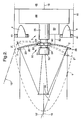
FIG. 2 shows a simplified longitudinal section throughFIG. 1 ; -
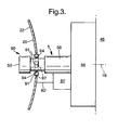
FIG. 3 shows simplified longitudinal section through part ofFIG. 1 at right angles toFIG. 2 ; -
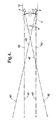
FIG. 4 is a simplified version ofFIG. 2 on a reduced scale illustrating the overlap of the fields of view of two laser detectors; and -
FIG. 5 shows a block diagram of a guidance system. - Referring now to
FIGS. 1 ,2 and3 , a radome 1 transparent to radiation of both millimeter and infra-red wavelengths covers the forward end of the body of amissile 10. Only the forward extremity of the missile is shown in the drawing. An annular array ofdiscrete laser receivers 4 is located within the radome 1.Receivers 4 are mounted in anannular support 41 which is secured to themissile body 10.Receivers 4 are thereby immovably attached (strapped down) to themissile body 10. The receivers per se are of the type described inU.S. Patent No. 5,784,156 , the contents of which are hereby incorporated by reference herein. As will be described in more detail below,receivers 4 are configured as a staring array looking generally ahead in the direction of travel of the missile. - A
concave reflector 2 has an annular peripheraldichroic region 22, an innerreflective region 20 and a central aperture 24.Dichroic region 22 transmits infra-red laser radiation and reflects microwave radiation. - A strap-down microwave detector, shown generally by 5, is mounted on a
first housing 44 containing microwave receiver components.Housing 44 is itself mounted on asecond housing 46 containing common processing circuitry for the microwave receiver and the laser receivers.Second housing 46 is attached to themissile body 10. -
Microwave detector 5 is generally cylindrical in shape and consists of aforward portion 52, anintermediate portion 54 and arearward portion 56.Forward portion 52 receives incident microwave radiation.Intermediate portion 54 is of smaller diameter thanforward portion 52 andrearward portion 56. -
Reflector 2 is mounted todetector 5 via agimbal arrangement 90 arranged within an aperture 24 at the center of thereflector 2. The gimbal arrangement consists of an annular ring-shaped member 91 having a first pair ofpivots 92 arranged on the opposite sides of the radially outer surface thereof by whichring 91 is coupled toreflector 2, and a second pair ofpivots 94 on opposite sides of the radially inner surface thereof by whichring 91 is coupled todetector 5. - A
convex reflector 3 has areflective surface 30 which reflects microwave radiation. Convexreflector 3 is attached to, and maintained in alignment with, theforward portion 52 ofdetector 5 bysupports 6. - Referring to
FIG. 2 , elevation adjustment ofreflector 2 is effected by afirst actuator 81 mounted on therearward portion 56 ofdetector 5 and coupled via a firstmechanical linkage 82 to the rear surface ofreflector 2. It will be seen that an incremental movement oflinkage 82 byactuator 81 will result in an incremental tilt ofreflector 2 in elevation.FIG. 3 shows the corresponding arrangement for adjusting azimuth consisting of a second actuator 81'and second linkage 82' arranged orthogonal to the elevation adjustment arrangement shown inFIG. 2 . Second actuator 81'and second linkage 82' ofFIG. 3 perform the same functions asfirst actuator 81 andfirst linkage 82 ofFIG. 2 but in respect of azimuth instead of elevation, and will therefore not be described further. - In the present embodiment,
concave reflector 2 consists of a polycarbonateconcave substrate 26 which is transparent to infra-red laser radiation. The concave surface of the substrate is coated with a thin layer of a metal which, in the present embodiment, is gold. The metal coating is continuous ininner region 20. In outerdichroic region 22, the metal coating is not continuous, metal being present in a pattern to leave areas of the substrate exposed. The dimensions of the metal-coated regions and exposed regions are such that infra-red laser radiation passes through outerdichroic region 22 with minimal attenuation, while microwave radiation is substantially totally reflected. The design and construction of such patterns exhibiting dichroic behavior are well known to those skilled in the art and will therefore not be described further. -
Concave reflector 2 may be moved from a position in which it detects radiation incident from theboresight axis 16 to a position, shown by dashed lines and indicated by primed numbers 2' where it detects radiation from an off-boresight direction as indicated by chain dashed lines 16'. - Gimbal 90,
actuators 81, 81' and associatedlinkages 82, 82',microwave detector 5 andsecondary reflector 3 are arranged in the radially central region ofprimary reflector 2 and, as such, do not obscure the field of view oflaser receivers 4. This means that by making the entire outer perimeter ofprimary reflector 2 transparent to infra-red laser light, an unobstructed field of view forreceivers 4 is obtained without physically mountingreceivers 4 on the same gimbaled platform as theconcave reflector 2. This allows laser receivers and microwave receiver to respond simultaneously to radiation from the same field of view. - As shown in
FIG.4 , beams 42 ofreceivers 4 overlap.Receivers 4 are arranged so that their combined fields of view cover a greater field of view than that of a single receiver and provide complete coverage of a predetermined field ahead of the missile. The overlap between the fields of the individual receivers is such that each point within the predetermined field lies within the field of view of at least two different laser receivers. It will be seen thatconvex reflector 3 does not obscure the field of view seen by the laser receivers. - Radiation received by the receivers is fed via fiber optic cables to a signal processing arrangement which determines the direction of incident laser radiation from the relative amplitudes of radiation received at different receivers. Such techniques are well known to the skilled person, inter alia, from
U.S. Patent No. 5,784,156 ; No.4,825,063 ; and No.4,674,874 , the contents of which are hereby incorporated herein by reference, and will not be described further. - The sensors disclosed in
U.S. Patent No. 5,784,156 are arranged at the exterior of a missile and thus look directly at their respective field of view. In the present invention, it will be appreciated thatreceivers 4 do not look directly at their respective fields of view, but look through bothdichroic region 22 ofreflector 2 and radome 1. Because radome 1 is in a fixed spatial relationship todetectors 4, any distortion in the wavefront of radiation incident onreceivers 4 caused by its passage through radome 1 which would make radiation appear to come from a different direction from its true bearing can be compensated for during calibration. Further wavefront distortion may arise from its passage throughdichroic region 22 ofreflector 2. Becausereflector 2 is movable, there is a possibility that distortion may vary with reflector position. If any such distortion has a significant effect on accuracy, it may be necessary to provide compensation. - This can be effected in a number of different ways according to operational requirements.
- If it is not necessary to use the laser receivers and microwave receiver simultaneously, then the reflector can be set to a predetermined position, e.g., aligned with the missile boresight, during laser reception. The system can then be calibrated with the reflector in the predetermined position. Alternatively, if simultaneous operation is required, then the laser receivers can be calibrated with the reflector in a number of different positions. The orientation of the reflector will, of course, be available from the circuitry which steers the reflector. Information about the radar reflector position can be used by the laser receiver processing circuitry to provide appropriate compensation, e. g., by using a look-up table and interpolation. Such compensation techniques are well known to the skilled person and will not be described further.
- Referring now to
FIG. 5 ,laser receivers 4 provide signals viafiber optic cables 402 tolaser processing circuit 40. Only twolaser receivers 4 are shown in the interest of clarity. Thelaser processing circuit 40 processes the signals oncables 402 and obtains therefrom information regarding the azimuth and elevation of a target in the manner described inU. S. Patent No. 5,784,156 . This information is supplied via line 404 to a first input of commonsensor processing circuit 60. - Received signals from millimeter
wave radar receiver 5 are supplied vialine 502 to millimeterwave processing circuit 50. Information about target bearing is fed vialine 504 to a second input of commonsensor processing circuit 60. Signals from commonsensor processing circuit 80 are fed vialine 522 toantenna steering circuit 52 which steers thesteerable reflector 2. Information about the position ofreflector 20 is fed fromantenna steering circuit 80 back to commonsensor processing circuit 60 vialine 524. Anoutput 602 of commonsensor processing circuit 60 provides steering commands to anautopilot 70 which steers the missile. - The components associated with the generation and transmission of millimeter wave radar signals are conventional. They have therefore been omitted in the interest of clarity as they are not relevant to the present invention.
- This tandem configuration of a gimbaled millimeter wave primary reflector and non-gimbaled laser receiver allows both the amount of electrical connections required and the gimbaled mass to be reduced, thereby reducing the demands on the actuators which steer the gimbaled reflector and providing instantaneous reception of laser pulses from the entire sensor field of view.
- While the above-described embodiment utilizes a Cassegrain-type reflector system, the invention is not limited thereto and may equally well be performed using other reflector configurations. For example, the microwave detector may be placed at the focus of the reflector system, the receiver beam being steered by moving the reflector system and receiver as a unit while the laser receiver array remains strapped down to its platform.
- Numerous modifications are possible within the scope of the invention. Instead of a pattern of conductors, the
dichroic region 22 may consist of a material such as indium tin oxide which possesses intrinsic dichroic properties, i.e., is transparent to infra-red radiation and reflects microwave radiation. - Alternatively, the
dichroic region 22 may consist of a continuous layer of metal, the layer being sufficiently thin to allow a significant amount of infra-red laser radiation to pass therethrough and sufficiently thick to reflect microwave radiation. The dichroic region may also be implemented using alternative frequency-selective resonant structures known per se which exhibit the necessary dichroic properties. - While in the described embodiment, the fixed
convex reflector 3 of the Cassegrain reflector is attached to the receiver it may alternatively be attached directly to the radome 1. - While the embodiment has a central aperture through which microwave radiation passes, this is not essential. In arrangements where the microwave receiver and gimbal lie wholly behind the primary reflector, and the substrate is intrinsically transparent to microwaves, the aperture may consist of an uncoated portion of the substrate, rather than a physical aperture per se. The transparent substrate need not be polycarbonate, but may be any other material having the necessary dimensional stability and transparency. It is evident that it is only necessary for the substrate to be transparent to those wavelengths to which the
receivers 4 therebehind are to respond. The transparency of the substrate to other wavelengths is irrelevant to the invention. - While the above described non-limiting embodiment has described the invention as applied to a missile, the invention is not limited thereto. It may be equally well applied to other guided munitions as well as other fields where sensors of two different wavelengths need to pass through a common aperture.
- Thus for use in space applications beyond planetary atmospheres, it is not necessary to provide a radome, which is provided only for aerodynamic streamlining.
- It will be seen that the present invention provides a dual frequency seeker that uses a tandem placement of the energy gathering systems for both laser and millimeter wave radiation. A feature of the invention is that the forward energy gathering system (the concave reflector) is constructed to be transparent to the frequency of the rear energy-collecting system (the laser detectors). The energy for the rear system passes through the forward system and is collected by the rear system. This arrangement allows the simultaneous use of the entire aperture for each of the frequencies. The other components of the seeker need not be placed in a tandem configuration. They can be placed in various configurations as long as the energy gathering systems are in tandem configuration. The tandem placement allows more streamlined dual sensor configurations allowing each of the sensors to perform to their own technical limit within the full diameter of the missile preserving each sensor's maximum detection ranges and aerodynamic performance. Common use of radomes, mounting structures and processors can significantly reduce the number of components while providing increased system performance. Parts count and complexity can be reduced, yielding lower costs.
Claims (7)
- A tandem laser and millimeter wave receiver for a moving vehicle and for providing directional information of a target to a guidance system (40, 50, 60, 70, 80) for the vehicle, comprising:a primary reflector (2) including a peripheral region (22) transparent to laser radiation and reflective to millimeter wave radiation;a secondary reflector (3) reflective to millimeter wave radiation and arranged to receive and reflect millimeter waves reflected from the primary reflector;annular laser receiver means including a plurality of discrete laser receiver means (4) arranged in a ring behind the peripheral region to receive laser radiation passing through the peripheral region;millimeter wave receiving means (5) for receiving the millimeter waves reflected from the secondary reflector;processor means (40, 50) for receiving signals from the annular laser receiver means and the millimeter wave receiving means, and for generating therefrom target position signals; andmeans for fastening the primary reflector, the secondary reflector, the annular laser receiver means, the millimeter wave receiving means, and the processor means together within an envelope (10) of the vehicle.
- The tandem receiver as claimed in claim 1; and further comprising a radome (1) transparent to millimeter waves and laser waves, and arranged to cover the reflectors (2, 3) and the laser and millimeter wave receiver means (4, 5).
- The tandem receiver as claimed in claim 1; and further comprising window means transparent to millimeter waves and laser waves, and arranged in front of the primary reflector (2) so that radiation sensed by the plurality of discrete laser receiver means (4) passes through the window means.
- The tandem receiver as claimed in claim 1, wherein the primary reflector (2) is movable.
- A guided munition including a tandem laser and millimeter wave receiver as claimed in any preceding claim.
- A missile including a tandem laser and millimeter wave receiver as claimed in any of claims 1 to 4.
- A guided munition as claimed in claim 5 or a missile as claimed in claim 6, wherein said primary reflector (2) is gimballed for movement relative to the envelope (10) and the annular laser receiver means (4) is fixed relative to the envelope.
Applications Claiming Priority (3)
| Application Number | Priority Date | Filing Date | Title |
|---|---|---|---|
| US09/454,541 US6268822B1 (en) | 1999-12-07 | 1999-12-07 | Dual-frequency millimeter wave and laser radiation receiver |
| US454541 | 1999-12-07 | ||
| PCT/IB2000/001865 WO2001042730A1 (en) | 1999-12-07 | 2000-12-05 | Dual-frequency millimeter wave and laser radiation receiver |
Publications (2)
| Publication Number | Publication Date |
|---|---|
| EP1322903A1 EP1322903A1 (en) | 2003-07-02 |
| EP1322903B1 true EP1322903B1 (en) | 2010-05-12 |
Family
ID=23805032
Family Applications (1)
| Application Number | Title | Priority Date | Filing Date |
|---|---|---|---|
| EP00981527A Expired - Lifetime EP1322903B1 (en) | 1999-12-07 | 2000-12-05 | Dual-frequency millimeter wave and laser radiation receiver |
Country Status (5)
| Country | Link |
|---|---|
| US (1) | US6268822B1 (en) |
| EP (1) | EP1322903B1 (en) |
| AU (1) | AU1876001A (en) |
| DE (1) | DE60044401D1 (en) |
| WO (1) | WO2001042730A1 (en) |
Families Citing this family (22)
| Publication number | Priority date | Publication date | Assignee | Title |
|---|---|---|---|---|
| GB9914162D0 (en) * | 1999-06-18 | 1999-08-18 | Secr Defence Brit | Steerable transponders |
| US7183966B1 (en) * | 2003-04-23 | 2007-02-27 | Lockheed Martin Corporation | Dual mode target sensing apparatus |
| US7142150B2 (en) * | 2004-12-15 | 2006-11-28 | Deere & Company | Method and system for detecting an object using a composite evidence grid |
| US7554076B2 (en) * | 2006-06-21 | 2009-06-30 | Northrop Grumman Corporation | Sensor system with modular optical transceivers |
| US7504993B2 (en) * | 2006-10-12 | 2009-03-17 | Agilent Technolgoies, Inc. | Coaxial bi-modal imaging system for combined microwave and optical imaging |
| US7786418B2 (en) * | 2008-11-21 | 2010-08-31 | Raytheon Company | Multimode seeker system with RF transparent stray light baffles |
| US8259291B2 (en) | 2009-06-04 | 2012-09-04 | Raytheon Company | Multi-band seeker with tiltable optical/receiver portion |
| GB0910662D0 (en) * | 2009-06-19 | 2009-10-28 | Mbda Uk Ltd | Improvements in or relating to antennas |
| US8164037B2 (en) * | 2009-09-26 | 2012-04-24 | Raytheon Company | Co-boresighted dual-mode SAL/IR seeker including a SAL spreader |
| US8581161B2 (en) | 2010-10-01 | 2013-11-12 | Raytheon Company | Seeker with a molded dichroic mirror |
| US8416127B2 (en) * | 2011-03-31 | 2013-04-09 | Raytheon Company | Dynamic calibration radar system |
| US8816901B2 (en) * | 2012-06-01 | 2014-08-26 | Honeywell International Inc. | Calibration to improve weather radar positioning determination |
| US8502128B1 (en) * | 2012-09-15 | 2013-08-06 | Raytheon Company | Dual-mode electro-optic sensor and method of using target designation as a guide star for wavefront error estimation |
| GB2515123B (en) * | 2013-06-14 | 2018-06-06 | Mbda Uk Ltd | Improvements in and relating to missile seekers |
| IL232381B (en) * | 2014-04-30 | 2020-02-27 | Israel Aerospace Ind Ltd | Cover |
| US9316463B2 (en) | 2014-05-09 | 2016-04-19 | Rosemount Aerospace Inc. | Multimode short wavelength infrared and radio-frequency seeker |
| IL233924B (en) * | 2014-08-03 | 2019-08-29 | Israel Aerospace Ind Ltd | Protective dome for a dual mode electromagnetic detection system |
| US10353064B2 (en) * | 2016-05-26 | 2019-07-16 | Decisive Analytics Corporation | Method and apparatus for detecting airborne objects |
| FR3059765B1 (en) * | 2016-12-07 | 2019-08-09 | Safran Electronics & Defense | HEAD FOR SELF-DIRECTING |
| GB2593533A (en) * | 2020-03-27 | 2021-09-29 | Metis Aerospace Ltd | UAV and UAV operator detector |
| US20240144835A1 (en) * | 2022-10-31 | 2024-05-02 | Joby Aero, Inc. | Systems and Methods for Radar-Based Aircraft Maneuver Actions |
| US12476383B1 (en) * | 2023-10-12 | 2025-11-18 | Rockwell Collins, Inc. | Integrated infrared imaging and passive seeker system for small munitions application |
Family Cites Families (32)
| Publication number | Priority date | Publication date | Assignee | Title |
|---|---|---|---|---|
| US3165749A (en) | 1958-09-15 | 1965-01-12 | Thompson Ramo Wooldridge Inc | Microwave transmissive optical radiation reflectors |
| US4085910A (en) * | 1972-04-12 | 1978-04-25 | Northrop Corporation | Dual mode optical seeker for guided missile control |
| US4108400A (en) * | 1976-08-02 | 1978-08-22 | The United States Of America As Represented By The Secretary Of The Navy | Dual mode guidance system |
| US4095230A (en) * | 1977-06-06 | 1978-06-13 | General Dynamics Corporation | High accuracy broadband antenna system |
| US4107529A (en) * | 1977-06-13 | 1978-08-15 | Sanders Associates, Inc. | Dual mode seeker reticle |
| US4282527A (en) | 1979-06-11 | 1981-08-04 | General Dynamics, Pomona Division | Multi-spectral detection system with common collecting means |
| US4348677A (en) * | 1979-06-25 | 1982-09-07 | General Dynamics, Pomona Division | Common aperture dual mode seeker antenna |
| US5538205A (en) * | 1980-02-11 | 1996-07-23 | Hughes Missile Systems Company | Inductive look angle sensor for a radiation seeker |
| US6150974A (en) | 1982-05-17 | 2000-11-21 | The United States Of America As Represented By The Secretary Of The Navy | Infrared transparent radar antenna |
| US4477814A (en) | 1982-08-02 | 1984-10-16 | The United States Of America As Represented By The Secretary Of The Air Force | Dual mode radio frequency-infrared frequency system |
| US4491845A (en) * | 1982-11-23 | 1985-01-01 | The United States Of America As Represented By The Secretary Of The Air Force | Wide angle phased array dome lens antenna with a reflection/transmission switch |
| DE3323828C2 (en) * | 1983-07-01 | 1986-01-16 | Messerschmitt-Bölkow-Blohm GmbH, 8012 Ottobrunn | Laser warning sensor |
| GB8326361D0 (en) * | 1983-10-01 | 1997-07-16 | British Aerospace | Dual mode radiation acceptors |
| US5182564A (en) * | 1984-07-26 | 1993-01-26 | The Boeing Company | Guidance apparatus with dual mode sensor |
| US4652885A (en) * | 1985-03-04 | 1987-03-24 | The United States Of America As Represented By The Secretary Of The Army | Dual mode antenna for millimeter wave and infrared radiation |
| US4636797A (en) * | 1985-03-04 | 1987-01-13 | The United States Of America As Represented By The Secretary Of The Army | Dual mode dichroic antenna/aperture |
| US4698638A (en) * | 1985-12-26 | 1987-10-06 | General Dynamics, Pomona Division | Dual mode target seeking system |
| EP0283538B1 (en) * | 1987-03-26 | 1990-08-16 | Messerschmitt-Bölkow-Blohm Gesellschaft mit beschränkter Haftung | Detector apparatus |
| US5023623A (en) * | 1989-12-21 | 1991-06-11 | Hughes Aircraft Company | Dual mode antenna apparatus having slotted waveguide and broadband arrays |
| US5214438A (en) | 1990-05-11 | 1993-05-25 | Westinghouse Electric Corp. | Millimeter wave and infrared sensor in a common receiving aperture |
| US5130718A (en) | 1990-10-23 | 1992-07-14 | Hughes Aircraft Company | Multiple dichroic surface cassegrain reflector |
| US5307077A (en) * | 1990-12-14 | 1994-04-26 | Hughes Missile Systems Company | Multi-spectral seeker antenna |
| US5214428A (en) | 1991-09-18 | 1993-05-25 | Gregory Allen | Data input grid for computer |
| US5327149A (en) * | 1992-05-18 | 1994-07-05 | Hughes Missile Systems Company | R.F. transparent RF/UV-IR detector apparatus |
| US5373302A (en) | 1992-06-24 | 1994-12-13 | The United States Of America As Represented By The Administrator Of The National Aeronautics And Space Administration | Double-loop frequency selective surfaces for multi frequency division multiplexing in a dual reflector antenna |
| US5394163A (en) * | 1992-08-26 | 1995-02-28 | Hughes Missile Systems Company | Annular slot patch excited array |
| US5447936A (en) | 1993-12-22 | 1995-09-05 | Bionumerik Pharmaceuticals, Inc. | Lactone stable formulation of 10-hydroxy 7-ethyl camptothecin and methods for uses thereof |
| DE9421991U1 (en) | 1994-03-03 | 1997-07-24 | Ingenieurbüro für Elektro-Mechanische Technologien, Dipl.-Ing. Hartmut Euer, 82377 Penzberg | Laser reflector device |
| US5458041A (en) * | 1994-08-02 | 1995-10-17 | Northrop Grumman Corporation | Air defense destruction missile weapon system |
| US5825063A (en) | 1995-03-07 | 1998-10-20 | California Institute Of Technology | Three-terminal silicon synaptic device |
| US5784156A (en) | 1996-11-19 | 1998-07-21 | Tracor Aerospace, Inc. | Fiber optic guidance system for laser guided missiles |
| US5973649A (en) * | 1997-10-28 | 1999-10-26 | Alliant Techsystems, Inc. | Common aperture dual mode semi-active laser/millimeter wave sensor |
-
1999
- 1999-12-07 US US09/454,541 patent/US6268822B1/en not_active Expired - Lifetime
-
2000
- 2000-12-05 DE DE60044401T patent/DE60044401D1/en not_active Expired - Lifetime
- 2000-12-05 EP EP00981527A patent/EP1322903B1/en not_active Expired - Lifetime
- 2000-12-05 AU AU18760/01A patent/AU1876001A/en not_active Abandoned
- 2000-12-05 WO PCT/IB2000/001865 patent/WO2001042730A1/en not_active Ceased
Also Published As
| Publication number | Publication date |
|---|---|
| AU1876001A (en) | 2001-06-18 |
| DE60044401D1 (en) | 2010-06-24 |
| US6268822B1 (en) | 2001-07-31 |
| WO2001042730A1 (en) | 2001-06-14 |
| EP1322903A1 (en) | 2003-07-02 |
Similar Documents
| Publication | Publication Date | Title |
|---|---|---|
| US6268822B1 (en) | Dual-frequency millimeter wave and laser radiation receiver | |
| US5307077A (en) | Multi-spectral seeker antenna | |
| US4652885A (en) | Dual mode antenna for millimeter wave and infrared radiation | |
| US4477814A (en) | Dual mode radio frequency-infrared frequency system | |
| US5182564A (en) | Guidance apparatus with dual mode sensor | |
| EP2443699B1 (en) | Improvements in or relating to antennas | |
| US5268680A (en) | Combined infrared-radar detection system | |
| JP3270548B2 (en) | Wide-field fixed body alignment direction measurement array | |
| EP1983612B1 (en) | Rotating screen dual reflector antenna | |
| US3114149A (en) | Combined radar and infra-red conical scanning antenna | |
| US4636797A (en) | Dual mode dichroic antenna/aperture | |
| US5298909A (en) | Coaxial multiple-mode antenna system | |
| USH1383H (en) | Space-based tethered phased-array antenna | |
| US5173699A (en) | Antenna arrangement | |
| US5319379A (en) | Parabolic dual reflector antenna with offset feed | |
| US3453633A (en) | Beam pointing and gain correction of large spherical antennas | |
| EP3047229B1 (en) | Improvements in and relating to missile seekers | |
| US5574461A (en) | Radar apparatus for connecting to a gun | |
| US4479129A (en) | Directive antenna system employing a paraboloidal main dish and ellipsoidal subdish | |
| US20040056813A1 (en) | Scanning antenna systems | |
| JPS62880A (en) | Electric wave and optical system composite seeker | |
| KR101968330B1 (en) | Homing apparatus with multiple sensor | |
| GB2188507A (en) | Target detection mechanism | |
| JP2538403B2 (en) | Lens antenna | |
| JPH03120488A (en) | Antenna for composite mode sensor |
Legal Events
| Date | Code | Title | Description |
|---|---|---|---|
| PUAI | Public reference made under article 153(3) epc to a published international application that has entered the european phase |
Free format text: ORIGINAL CODE: 0009012 |
|
| 17P | Request for examination filed |
Effective date: 20020626 |
|
| AK | Designated contracting states |
Designated state(s): AT BE CH CY DE FR GB IT LI |
|
| AX | Request for extension of the european patent |
Extension state: AL LT LV MK RO SI |
|
| 17Q | First examination report despatched |
Effective date: 20080109 |
|
| GRAP | Despatch of communication of intention to grant a patent |
Free format text: ORIGINAL CODE: EPIDOSNIGR1 |
|
| GRAS | Grant fee paid |
Free format text: ORIGINAL CODE: EPIDOSNIGR3 |
|
| RBV | Designated contracting states (corrected) |
Designated state(s): DE FR GB IT |
|
| GRAA | (expected) grant |
Free format text: ORIGINAL CODE: 0009210 |
|
| AK | Designated contracting states |
Kind code of ref document: B1 Designated state(s): DE FR GB IT |
|
| REG | Reference to a national code |
Ref country code: GB Ref legal event code: FG4D |
|
| REF | Corresponds to: |
Ref document number: 60044401 Country of ref document: DE Date of ref document: 20100624 Kind code of ref document: P |
|
| PLBE | No opposition filed within time limit |
Free format text: ORIGINAL CODE: 0009261 |
|
| STAA | Information on the status of an ep patent application or granted ep patent |
Free format text: STATUS: NO OPPOSITION FILED WITHIN TIME LIMIT |
|
| 26N | No opposition filed |
Effective date: 20110215 |
|
| REG | Reference to a national code |
Ref country code: DE Ref legal event code: R097 Ref document number: 60044401 Country of ref document: DE Effective date: 20110214 |
|
| REG | Reference to a national code |
Ref country code: FR Ref legal event code: PLFP Year of fee payment: 16 |
|
| REG | Reference to a national code |
Ref country code: FR Ref legal event code: PLFP Year of fee payment: 17 |
|
| REG | Reference to a national code |
Ref country code: FR Ref legal event code: PLFP Year of fee payment: 18 |
|
| PGFP | Annual fee paid to national office [announced via postgrant information from national office to epo] |
Ref country code: FR Payment date: 20191223 Year of fee payment: 20 |
|
| PGFP | Annual fee paid to national office [announced via postgrant information from national office to epo] |
Ref country code: GB Payment date: 20191226 Year of fee payment: 20 Ref country code: IT Payment date: 20191223 Year of fee payment: 20 Ref country code: DE Payment date: 20191230 Year of fee payment: 20 |
|
| REG | Reference to a national code |
Ref country code: DE Ref legal event code: R071 Ref document number: 60044401 Country of ref document: DE |
|
| REG | Reference to a national code |
Ref country code: GB Ref legal event code: PE20 Expiry date: 20201204 |
|
| PG25 | Lapsed in a contracting state [announced via postgrant information from national office to epo] |
Ref country code: GB Free format text: LAPSE BECAUSE OF EXPIRATION OF PROTECTION Effective date: 20201204 |