EP1322353B1 - Multiple processing chamber set and use thereof - Google Patents
Multiple processing chamber set and use thereof Download PDFInfo
- Publication number
- EP1322353B1 EP1322353B1 EP01977483A EP01977483A EP1322353B1 EP 1322353 B1 EP1322353 B1 EP 1322353B1 EP 01977483 A EP01977483 A EP 01977483A EP 01977483 A EP01977483 A EP 01977483A EP 1322353 B1 EP1322353 B1 EP 1322353B1
- Authority
- EP
- European Patent Office
- Prior art keywords
- chambers
- expressor
- processing
- fluid
- bag
- Prior art date
- Legal status (The legal status is an assumption and is not a legal conclusion. Google has not performed a legal analysis and makes no representation as to the accuracy of the status listed.)
- Expired - Lifetime
Links
- 239000012530 fluid Substances 0.000 claims abstract description 66
- 238000004891 communication Methods 0.000 claims abstract description 7
- 238000000034 method Methods 0.000 claims description 19
- 230000037361 pathway Effects 0.000 claims description 10
- 239000000463 material Substances 0.000 claims description 9
- 238000005119 centrifugation Methods 0.000 claims description 8
- 239000006228 supernatant Substances 0.000 claims description 7
- 239000008188 pellet Substances 0.000 claims description 3
- 239000000203 mixture Substances 0.000 claims 1
- 239000000306 component Substances 0.000 description 17
- 210000004027 cell Anatomy 0.000 description 15
- 210000004369 blood Anatomy 0.000 description 14
- 239000008280 blood Substances 0.000 description 14
- 239000000523 sample Substances 0.000 description 6
- 210000003743 erythrocyte Anatomy 0.000 description 5
- 239000012503 blood component Substances 0.000 description 4
- 230000000295 complement effect Effects 0.000 description 4
- 230000000712 assembly Effects 0.000 description 3
- 238000000429 assembly Methods 0.000 description 3
- 239000012472 biological sample Substances 0.000 description 3
- 238000010276 construction Methods 0.000 description 3
- 238000000926 separation method Methods 0.000 description 3
- 239000000126 substance Substances 0.000 description 3
- 238000006243 chemical reaction Methods 0.000 description 2
- 230000002255 enzymatic effect Effects 0.000 description 2
- 230000002779 inactivation Effects 0.000 description 2
- 230000036512 infertility Effects 0.000 description 2
- 230000013011 mating Effects 0.000 description 2
- 238000012986 modification Methods 0.000 description 2
- 230000004048 modification Effects 0.000 description 2
- 244000052769 pathogen Species 0.000 description 2
- 230000001717 pathogenic effect Effects 0.000 description 2
- 230000002093 peripheral effect Effects 0.000 description 2
- 150000003839 salts Chemical class 0.000 description 2
- 238000005406 washing Methods 0.000 description 2
- 102000004190 Enzymes Human genes 0.000 description 1
- 108090000790 Enzymes Proteins 0.000 description 1
- 230000001133 acceleration Effects 0.000 description 1
- 239000013060 biological fluid Substances 0.000 description 1
- 239000000872 buffer Substances 0.000 description 1
- 210000000265 leukocyte Anatomy 0.000 description 1
- 239000000047 product Substances 0.000 description 1
- 239000002699 waste material Substances 0.000 description 1
Images



Classifications
-
- A—HUMAN NECESSITIES
- A61—MEDICAL OR VETERINARY SCIENCE; HYGIENE
- A61M—DEVICES FOR INTRODUCING MEDIA INTO, OR ONTO, THE BODY; DEVICES FOR TRANSDUCING BODY MEDIA OR FOR TAKING MEDIA FROM THE BODY; DEVICES FOR PRODUCING OR ENDING SLEEP OR STUPOR
- A61M1/00—Suction or pumping devices for medical purposes; Devices for carrying-off, for treatment of, or for carrying-over, body-liquids; Drainage systems
- A61M1/36—Other treatment of blood in a by-pass of the natural circulatory system, e.g. temperature adaptation, irradiation ; Extra-corporeal blood circuits
- A61M1/3693—Other treatment of blood in a by-pass of the natural circulatory system, e.g. temperature adaptation, irradiation ; Extra-corporeal blood circuits using separation based on different densities of components, e.g. centrifuging
-
- A—HUMAN NECESSITIES
- A61—MEDICAL OR VETERINARY SCIENCE; HYGIENE
- A61M—DEVICES FOR INTRODUCING MEDIA INTO, OR ONTO, THE BODY; DEVICES FOR TRANSDUCING BODY MEDIA OR FOR TAKING MEDIA FROM THE BODY; DEVICES FOR PRODUCING OR ENDING SLEEP OR STUPOR
- A61M1/00—Suction or pumping devices for medical purposes; Devices for carrying-off, for treatment of, or for carrying-over, body-liquids; Drainage systems
- A61M1/36—Other treatment of blood in a by-pass of the natural circulatory system, e.g. temperature adaptation, irradiation ; Extra-corporeal blood circuits
- A61M1/3692—Washing or rinsing blood or blood constituents
-
- A—HUMAN NECESSITIES
- A61—MEDICAL OR VETERINARY SCIENCE; HYGIENE
- A61M—DEVICES FOR INTRODUCING MEDIA INTO, OR ONTO, THE BODY; DEVICES FOR TRANSDUCING BODY MEDIA OR FOR TAKING MEDIA FROM THE BODY; DEVICES FOR PRODUCING OR ENDING SLEEP OR STUPOR
- A61M1/00—Suction or pumping devices for medical purposes; Devices for carrying-off, for treatment of, or for carrying-over, body-liquids; Drainage systems
- A61M1/36—Other treatment of blood in a by-pass of the natural circulatory system, e.g. temperature adaptation, irradiation ; Extra-corporeal blood circuits
- A61M1/3693—Other treatment of blood in a by-pass of the natural circulatory system, e.g. temperature adaptation, irradiation ; Extra-corporeal blood circuits using separation based on different densities of components, e.g. centrifuging
- A61M1/3696—Other treatment of blood in a by-pass of the natural circulatory system, e.g. temperature adaptation, irradiation ; Extra-corporeal blood circuits using separation based on different densities of components, e.g. centrifuging with means for adding or withdrawing liquid substances during the centrifugation, e.g. continuous centrifugation
-
- A—HUMAN NECESSITIES
- A61—MEDICAL OR VETERINARY SCIENCE; HYGIENE
- A61M—DEVICES FOR INTRODUCING MEDIA INTO, OR ONTO, THE BODY; DEVICES FOR TRANSDUCING BODY MEDIA OR FOR TAKING MEDIA FROM THE BODY; DEVICES FOR PRODUCING OR ENDING SLEEP OR STUPOR
- A61M1/00—Suction or pumping devices for medical purposes; Devices for carrying-off, for treatment of, or for carrying-over, body-liquids; Drainage systems
- A61M1/36—Other treatment of blood in a by-pass of the natural circulatory system, e.g. temperature adaptation, irradiation ; Extra-corporeal blood circuits
- A61M1/3693—Other treatment of blood in a by-pass of the natural circulatory system, e.g. temperature adaptation, irradiation ; Extra-corporeal blood circuits using separation based on different densities of components, e.g. centrifuging
- A61M1/3698—Expressing processed fluid out from the turning rotor using another fluid compressing the treatment chamber; Variable volume rotors
-
- B—PERFORMING OPERATIONS; TRANSPORTING
- B04—CENTRIFUGAL APPARATUS OR MACHINES FOR CARRYING-OUT PHYSICAL OR CHEMICAL PROCESSES
- B04B—CENTRIFUGES
- B04B5/00—Other centrifuges
- B04B5/04—Radial chamber apparatus for separating predominantly liquid mixtures, e.g. butyrometers
- B04B5/0407—Radial chamber apparatus for separating predominantly liquid mixtures, e.g. butyrometers for liquids contained in receptacles
- B04B5/0428—Radial chamber apparatus for separating predominantly liquid mixtures, e.g. butyrometers for liquids contained in receptacles with flexible receptacles
-
- A—HUMAN NECESSITIES
- A61—MEDICAL OR VETERINARY SCIENCE; HYGIENE
- A61M—DEVICES FOR INTRODUCING MEDIA INTO, OR ONTO, THE BODY; DEVICES FOR TRANSDUCING BODY MEDIA OR FOR TAKING MEDIA FROM THE BODY; DEVICES FOR PRODUCING OR ENDING SLEEP OR STUPOR
- A61M1/00—Suction or pumping devices for medical purposes; Devices for carrying-off, for treatment of, or for carrying-over, body-liquids; Drainage systems
- A61M1/02—Blood transfusion apparatus
- A61M1/0209—Multiple bag systems for separating or storing blood components
-
- A—HUMAN NECESSITIES
- A61—MEDICAL OR VETERINARY SCIENCE; HYGIENE
- A61M—DEVICES FOR INTRODUCING MEDIA INTO, OR ONTO, THE BODY; DEVICES FOR TRANSDUCING BODY MEDIA OR FOR TAKING MEDIA FROM THE BODY; DEVICES FOR PRODUCING OR ENDING SLEEP OR STUPOR
- A61M1/00—Suction or pumping devices for medical purposes; Devices for carrying-off, for treatment of, or for carrying-over, body-liquids; Drainage systems
- A61M1/36—Other treatment of blood in a by-pass of the natural circulatory system, e.g. temperature adaptation, irradiation ; Extra-corporeal blood circuits
- A61M1/3687—Chemical treatment
-
- A—HUMAN NECESSITIES
- A61—MEDICAL OR VETERINARY SCIENCE; HYGIENE
- A61M—DEVICES FOR INTRODUCING MEDIA INTO, OR ONTO, THE BODY; DEVICES FOR TRANSDUCING BODY MEDIA OR FOR TAKING MEDIA FROM THE BODY; DEVICES FOR PRODUCING OR ENDING SLEEP OR STUPOR
- A61M2202/00—Special media to be introduced, removed or treated
- A61M2202/04—Liquids
- A61M2202/0413—Blood
- A61M2202/0429—Red blood cells; Erythrocytes
-
- A—HUMAN NECESSITIES
- A61—MEDICAL OR VETERINARY SCIENCE; HYGIENE
- A61M—DEVICES FOR INTRODUCING MEDIA INTO, OR ONTO, THE BODY; DEVICES FOR TRANSDUCING BODY MEDIA OR FOR TAKING MEDIA FROM THE BODY; DEVICES FOR PRODUCING OR ENDING SLEEP OR STUPOR
- A61M2205/00—General characteristics of the apparatus
- A61M2205/60—General characteristics of the apparatus with identification means
- A61M2205/6045—General characteristics of the apparatus with identification means having complementary physical shapes for indexing or registration purposes
-
- A—HUMAN NECESSITIES
- A61—MEDICAL OR VETERINARY SCIENCE; HYGIENE
- A61M—DEVICES FOR INTRODUCING MEDIA INTO, OR ONTO, THE BODY; DEVICES FOR TRANSDUCING BODY MEDIA OR FOR TAKING MEDIA FROM THE BODY; DEVICES FOR PRODUCING OR ENDING SLEEP OR STUPOR
- A61M39/00—Tubes, tube connectors, tube couplings, valves, access sites or the like, specially adapted for medical use
Definitions
- the invention relates to processing chambers sets for independently and/or simultaneously processing multiple samples of biological cells in a processing device.
- Flexible processing chambers for processing biological cells in a fixed volume centrifuge, and methods for use of such processing bags, e.g., by centrifugation, are known.
- PCT patent application PCT/US98/10406 describes a flexible cell processing chamber having a rotating seal to keep the contents of the chamber sterile during processing.
- Flexible processing chambers advantageously are disposable and thus suitable for single-use sterile applications.
- WO9200145 relates to a method and to a device for separating blood present in a blood container into components by centrifuging the blood, and for transmitting at least one of three stratified components obtained by centrifugation in sterile fashion to a respective side container connected to the blood container via a respective hose.
- the present invention provides a multiple processing chamber set for biological cell processing in a centrifugal device including processing bags and expression bags.
- the invention also provides methods for use of such a multiple processing chamber set for biological cell processing in a centrifugal device, including independent and/or simultaneous addition to or expression of contents from the multiple chambers.
- a multiple sample processing apparatus for a continuous flow centrifuge provided.
- the processing and expressor chambers are constructed and arranged to be flexible and expandable, preferably the chambers are constructed and arranged to releasably contact each other at a circumferential portion of the chambers when the expressor chambers are filled with an expressor fluid.
- the processor bag and expressor bags may be alternately arranged.
- the central hubs are constructed and arranged to prevent construction of an apparatus having two adjacent processing chambers.
- the central hubs of the processing chambers may have a generally disc-like shape with non-complementary sides, such as non-complementary male and female connector shapes.
- the central hubs of the expressor bags also are constructed and arranged to prevent construction of an apparatus having two adjacent expressor chambers, in a like fashion.
- the apparatus uses two sets of central hubs, with the shape of one side of the processing chamber central hub being complementary in shape only with one side of the expressor chamber central hub, and the shape of the other (second) side of the processing chamber central hub being complementary in shape only with the other (second) side of the expressor chamber central hub.
- the central hubs are constructed and arranged to define multiple passages for fluid communication, preferably a number of passages that is at least equal to the number of chambers in the apparatus.
- the central hubs when connected together, provide continuous unique fluid passages between each chamber and one of more external fluid supplies.
- the apparatus also preferably includes a plurality of weld rings disposed on the central hubs, the weld rings being constructed and arranged to permit attachment of processing chambers and expressor chambers, which may be alternately arranged.
- the processing chambers and expressor chambers are substantially the same shape, preferably a substantially circular shape, and most preferably having substantially the same diameter.
- the processing chambers and expressor chambers are constructed from two sheets of flexible material, the two sheets of material sealed at an outer circumference and an inner circumference, although other constructions are also possible and permissible.
- the inner circumference is substantially adjacent the axial opening.
- the apparatus in other preferred embodiment also includes a terminal central hub, disposed at a terminus of the plurality of axially aligned alternating processing chambers and expressor chambers.
- the terminal central hub constructed and arranged to terminate fluid flow through the central hub fluid passages.
- a fluid entry hub is disposed at a fluid entry point of the plurality of axially aligned alternating processing chambers and expressor chambers, and is constructed and arranged to serve as an interface for fluid communication between the plurality of axially aligned alternating processing chambers and expressor chambers and a fluid pathway external to the continuous flow centrifuge.
- the fluid pathway is a multi-lumen tube.
- a method for independently and simultaneously processing a plurality of samples in a centrifugal device according to claim 18 is provided.
- the method includes adding one or more processing fluids to the plurality of samples or pellets. In other preferred embodiments, a portion of one or more of the plurality of samples is expressed independently from the remaining samples. In further preferred embodiments, process fluids are added to one or more of the plurality of samples independently from the remaining samples.
- the invention provides multiple processing chamber sets for processing simultaneously and independently a number of separate samples at one time in a centrifugal cell processing device.
- the multiple processing chamber sets permit sterile addition and removal of samples (and processed fractions thereof), processing fluids (including enzymes, salts, buffers and other process chemicals), and waste products without the need for rotating seals of any kind.
- the multiple processing chamber set represents a portion of a closed system for biological cell processing and includes a number of separate closed containers that can be treated in series or in parallel.
- the multiple processing chamber set includes sequentially alternating processing and expressor flexible chambers (also referred to herein as "bags") such that each processing bag is in contact with one or more expressor bags.
- the expressor (E) and processing (P) bags are provided in a 1:1 ratio and are alternated in the sequence:
- the expressor and processing bags are provided in a 2:1 ratio, sequenced to surround each processing bag P with its own set of two expressor bags:
- the multiple processing chamber sets of the invention can theoretically have any specific number of bags, from two to infinity, to process a like number of samples.
- the number of bags will usually correspond to the number of units or blood to be processed.
- a multiple processing chamber set can be selected that has the appropriate number of processing bags.
- one or more of the processing bags can optionally be left unfilled or filled with a solution that is not processed if the multiple processing clamber set used contains a greater number of processing bags than the number of samples to be processed.
- the optimal number and configuration of bags in the multiple processing chamber set may be constrained by the size and capacity of the centrifugal device, the materials used, or other factors known to one of ordinary skill in the art.
- the multiple processing chamber sets of the invention have between 4 and 16 processing bags, and more preferably have between 8 and 12 processing bags, with appropriate numbers of expressing bags interspersed as described above.
- the processing and expressor bags may be placed in the above mentioned alternating sequence with an orientation that places all bags or chambers along a centrally located axis of rotation.
- the chambers are all axially aligned, i.e., stacked (see Fig. 9 , item 92).
- This axis is defined on each bag by noting the largest bag surface area and finding the center of rotation perpendicular to the largest bag or chamber surface.
- the bags are circular in shape, although other shapes may be used.
- Each processing or expressor bag is comprised of a flexible compartment, a central hub and weld rings for connecting the flexible compartment to the central hub.
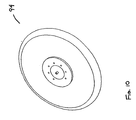
- the bags 10, 50 have an axial aperture 11, 51 where the central hub is joined.
- the flexible compartment of the processing bag and central hub are constructed of a plastic material that is able to withstand a variety of processing conditions including, but not limited to, changes in temperature, pH, and salt concentrations; application of acceleration, deceleration and centrifugal forces; and application of force from inflation or expansion of the expressor bags.
- the flexible compartment of the expressor bag is constructed of a plastic material that is able to withstand inflation with expressor fluid or gas.
- the flexible compartments of the processing and expressor bags are constructed using a PVC material.
- the central hubs and weld rings are constructed using a rigid plastic material.
- the central plastic hubs for the processing and expressing chambers are notably different and interlock such that, for proper assembly of multiple processing chamber sets, the alternating sequence of processing and expressing bags in a 1:1 ratio must be maintained.
- Each of these respective central hubs has a different male-female connection to prevent connection with a like hub.
- the outer ring 61 that surrounds the male connector 64 of the processing hub will prevent mating with another processing central hub, but fits the outer flange 21 to permit mating with one side of the expressor central hub (middle view).
- peripheral holes 22, 62 When appropriately mated, matching features of the processing and expressor central hubs will align, e.g., peripheral holes 22, 62, and central holes 23, 63 in all cases; as well as one of the following sets of surfaces: surfaces 24, 64 and 25, 65 or surfaces 26, 66 and 27, 67.
- Other features of the central hubs provide for proper rotational orientation of the expressor and processing hubs relative to each other to prevent misalignment of peripheral holes 22, 62.
- a different geometry may be provided for the central plastic hubs that connect the two expressor bags inserted between two processing bags (i.e., the connection underlined: P-E-E-P).
- Each of the central hubs contains several independent fluid pathways or passages (e.g., through holes 22, 62 and holes 23, 63 of the central hubs) that interconnect with like passages on subsequent hubs during assembly.
- the interlocking nature of the hubs forces the fluid pathways to be consistent throughout the assembly such that all fluid pathways maintain independence from one another.
- a single fluid pathway is formed inside the assembled set of hubs that communicates with all the expressing bags or chambers (through holes 23, 63).
- each processing chamber or bag has a unique and independent fluid pathway through the assembled set of hubs (through holes 22, 62).
- the multiple processing chamber set (bag set) is defined as any number of processing bags and associated expressing bags assembled together with central hubs in place.
- the steps of assembling expressor bags are depicted in Figs. 3 and 4 .
- Fig. 3 is a side view of the expressor bag assembly, showing the weld rings 30 prior to joining with the expressor bag/central hub assembly 31 (left view) and after joining (right view) to form a fully assembled expressor bag assembly 32.
- Fig. 4 is a perspective view of one side of the expressor bag assembly, showing the expressor bag/central hub assembly 41 (right view) prior to joining with the weld ring 40, and after the joining (left view) to form a fully assembled expressor bag assembly 42.
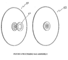
- Figs. 7 and 8 are side views of the processing bag assembly, showing the weld rings 70 prior to joining with the processing bag/central hub assembly 71 (left view) and after joining (right view) to form a fully assembled processing bag assembly 72.
- Fig. 8 is a perspective view of one side of the processing bag assembly, showing the processing bag/central hub assembly 81 (left view) prior to joining with the weld ring 80, and after the joining (right view) to form a fully assembled processing bag assembly 82.
- a completed bag set assembly 90 (i.e., a multiple processing chamber set) is depicted in Fig. 9 .
- Fluid entry hub 91 forms the interface between a multi-lumen tube 93 and the assembled processing/expressor bags 92.
- the multi-lumen tube preferably includes at least as many lumens as there are processing and expressor bags.
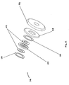
- multiple sets of expressor bag and processing bag combinations are assembled in a 1:1 ratio, except that the processor bag is sized smaller than the expressor bag and is placed within the expressor bag, yielding a "bag within a bag" assembly illustrated in Figs. 10-12 .
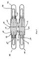
- the bag within a bag assembly 94 includes the outer expressor bag 96, an inner processing bag 98, outer weld rings 100, inner weld rings 102 and hub 104.
- a conduit 106 allows an expressor fluid to be pumped into (and out of) the expressor bag, so that ports 108 allow the supernatant or separated components to flow out of the processing bag via conduit 110.
- the hub is designed so that multiple assemblies may be assembled together. Specifically, one side of the hub includes a recess 112 while the other side includes a protruding portion 114 of the conduit 106. Thus, the recess 112 receives a corresponding protruding portion 114 of an adjacent bag within a bag assembly.
- the invention further includes a method for independently and simultaneously processing multiple samples in a centrifugal device.
- the invention provides for the use of a multiple processing chamber set in the processing of biological cells according to defined protocols in a cell processing device.
- the method is useful for cell washing, blood component separation, blood component processing, including enzymatic conversion of the blood type of red blood cells (e.g., types A, B or AB to type O red blood cells), pathogen inactivation of biological fluids or cells, and the like.
- the methods utilize a defined processing protocol that involves adding one or more samples to the processing bags of the multiple processing chamber set, optionally centrifuging the samples, optionally expressing a supernatant formed by the centrifugation, adding one or more process chemicals or fluids, etc. Processing protocols are known to those of skill in the art, and an exemplary method follows.
- the method of separating or processing samples can be defined in several steps subsequent to the assembly of the bag set
- the initial step involves mounting the bag set into a continuous fixed volume centrifuge.
- the fluid e.g., blood
- the centrifuge is slowed to expression speed while the component interface is maintained.
- expressor fluid see, e.g., PCT patent application PCT/US98/10406
- the overall volume of the centrifuge compartment available to the processing bags is reduced proportionally.
- the contents of the processing bag are emptied or expressed. Further, the contents of the processing bags are expressed preferentially from least dense to most dense due to the centrifugation and the fact that expressor fluid is denser that the densest component held within the processing chamber.
- the expressor fluid may include two fluid components that, when mixed together, create a fluid that is heavier than the heaviest component of the biological sample.
- the biological sample is blood
- the two fluid components mixed create a fluid heavier than the red blood cell component (i.e., the heaviest component) of blood, so that all the components of the blood (e.g., red blood cells, white blood cells, palettes) may be separated and removed from the processing bags.
- the expressor fluid may not be required to be heavier than the heaviest component of the sample.
- an expressor fluid comprised substantially of air may be used.
- the expressor fluid will fill the expressor bags from the outermost radial portion inward to the innermost radial portion as disclosed in PCT patent application PCT/US98/10406 .
- the reduced volume within the processing bags causes the fluid at the innermost radial portion of the processing bags to be expressed.
- the expressor fluid can be removed, if desired, from the expressor bags by the application of a vacuum to the expressor bag supply line(s), the use of expressor fluid also permits the adjustment of the volume of the processing bags as needed, for example, for different protocols or for different steps of a single protocol.
- air is used as the expressor fluid, it may be removed in a much shorter period of time than the usual heavier expressor fluids used to separate more components of the sample.
- Subsequent protocol steps may include washing of cells after supernatants are expressed. Wash fluids and/or processing fluids, etc., are introduced into the processing bags as the sample was, and incubated with the sample.
- the processing bags may be agitated is desired by reversing the direction of the centrifuge drive, by running the centrifuge intermittently, and so on.
Landscapes
- Health & Medical Sciences (AREA)
- Heart & Thoracic Surgery (AREA)
- Vascular Medicine (AREA)
- General Health & Medical Sciences (AREA)
- Veterinary Medicine (AREA)
- Anesthesiology (AREA)
- Biomedical Technology (AREA)
- Hematology (AREA)
- Life Sciences & Earth Sciences (AREA)
- Animal Behavior & Ethology (AREA)
- Cardiology (AREA)
- Public Health (AREA)
- Engineering & Computer Science (AREA)
- Centrifugal Separators (AREA)
- External Artificial Organs (AREA)
- Physical Deposition Of Substances That Are Components Of Semiconductor Devices (AREA)
- Investigating Or Analysing Biological Materials (AREA)
- Automatic Analysis And Handling Materials Therefor (AREA)
- Massaging Devices (AREA)
- Pharmaceuticals Containing Other Organic And Inorganic Compounds (AREA)
- Apparatus Associated With Microorganisms And Enzymes (AREA)
Abstract
Description
- The invention relates to processing chambers sets for independently and/or simultaneously processing multiple samples of biological cells in a processing device.
- Flexible processing chambers (bags) for processing biological cells in a fixed volume centrifuge, and methods for use of such processing bags, e.g., by centrifugation, are known. For example, PCT patent application
PCT/US98/10406 - For certain applications, such as blood processing including blood component separation, enzymatic conversion of blood type, and pathogen inactivation of blood components, it is desirable to process multiple units at a time, in a single instrument under the same conditions. Simultaneous processing of multiple units reduces the time and expense required to perform such applications. Present flexible processing chambers do not provide the ability to perform independent simultaneous processing of multiple samples.
-
WO9200145 - One of the difficulties in constructing a multiple processing chamber set is the expression of the contents of the multiple chambers. In any processing protocol, it may be necessary to add and remove processing solutions and chemicals during several steps of the protocol. Thus, it is necessary to be able to efficiently remove the contents of the multiple chambers, usually the supernatant following centrifugation, in a manner that retains the integrity of the multiple chambers and the sterility of the contents contained therein. Accordingly, there is a need for a multiple processing chamber set for biological cell processing in a centrifugal device that maintains sterility of the processed cells and provides for efficient addition and removal of cell samples and processing solutions from multiple chambers simultaneously and/or independently.
- The present invention provides a multiple processing chamber set for biological cell processing in a centrifugal device including processing bags and expression bags. The invention also provides methods for use of such a multiple processing chamber set for biological cell processing in a centrifugal device, including independent and/or simultaneous addition to or expression of contents from the multiple chambers.
- According to a first aspect of the invention, a multiple sample processing apparatus for a continuous flow centrifuge provided. In preferred embodiments, the processing and expressor chambers are constructed and arranged to be flexible and expandable, preferably the chambers are constructed and arranged to releasably contact each other at a circumferential portion of the chambers when the expressor chambers are filled with an expressor fluid. The processor bag and expressor bags may be alternately arranged.
- In the first aspect according to claim 1 is, the central hubs are constructed and arranged to prevent construction of an apparatus having two adjacent processing chambers. The central hubs of the processing chambers may have a generally disc-like shape with non-complementary sides, such as non-complementary male and female connector shapes. Preferably the central hubs of the expressor bags also are constructed and arranged to prevent construction of an apparatus having two adjacent expressor chambers, in a like fashion. Most preferably the apparatus uses two sets of central hubs, with the shape of one side of the processing chamber central hub being complementary in shape only with one side of the expressor chamber central hub, and the shape of the other (second) side of the processing chamber central hub being complementary in shape only with the other (second) side of the expressor chamber central hub.
- In other preferred embodiments, the central hubs are constructed and arranged to define multiple passages for fluid communication, preferably a number of passages that is at least equal to the number of chambers in the apparatus. Thus the central hubs, when connected together, provide continuous unique fluid passages between each chamber and one of more external fluid supplies.
- The apparatus also preferably includes a plurality of weld rings disposed on the central hubs, the weld rings being constructed and arranged to permit attachment of processing chambers and expressor chambers, which may be alternately arranged.
- In certain preferred embodiments of the invention, the processing chambers and expressor chambers are substantially the same shape, preferably a substantially circular shape, and most preferably having substantially the same diameter. In some embodiments the processing chambers and expressor chambers are constructed from two sheets of flexible material, the two sheets of material sealed at an outer circumference and an inner circumference, although other constructions are also possible and permissible. Preferably, the inner circumference is substantially adjacent the axial opening.
- The apparatus in other preferred embodiment also includes a terminal central hub, disposed at a terminus of the plurality of axially aligned alternating processing chambers and expressor chambers. Preferably, the terminal central hub constructed and arranged to terminate fluid flow through the central hub fluid passages.
- In additional embodiments, a fluid entry hub is disposed at a fluid entry point of the plurality of axially aligned alternating processing chambers and expressor chambers, and is constructed and arranged to serve as an interface for fluid communication between the plurality of axially aligned alternating processing chambers and expressor chambers and a fluid pathway external to the continuous flow centrifuge. Preferably, the fluid pathway is a multi-lumen tube.
- According to a second aspect of the invention, a method for independently and simultaneously processing a plurality of samples in a centrifugal device according to claim 18 is provided.
- In certain preferred embodiments, the method includes adding one or more processing fluids to the plurality of samples or pellets. In other preferred embodiments, a portion of one or more of the plurality of samples is expressed independently from the remaining samples. In further preferred embodiments, process fluids are added to one or more of the plurality of samples independently from the remaining samples.
- These and other aspects of the invention will be described in connection with the drawings and the detailed description below.
-
-
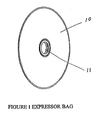
Fig. 1 depicts an expressor bag having an axial opening. -
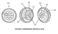
Fig. 2 depicts three views of an expressor central hub. -
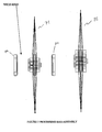
Fig. 3 depicts the assembly of an expressor bag by joining two weld rings to an expressor bag and central hub. -
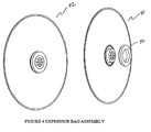
Fig. 4 depicts a perspective view of the joining of one weld ring to an expressor bag and central hub. -
Fig. 5 depicts a processing bag having an axial opening. -
Fig. 6 depicts three views of a processing central hub. -
Fig. 7 depicts the assembly of a processing bag by joining two weld rings to a processing bag and central hub. -
Fig. 8 depicts a perspective view of the joining of one weld ring to a processing bag and central hub. -
Fig. 9 depicts a bag set assembly with six alternating expressor andprocessing bags 92, afluid entry hub 91 and afluid supply tube 93. -
Fig. 10 depicts a side view of a bag set of an assembly of a processor bag within an expressor bag embodiment. -
Fig. 11 depicts a cross-sectional side view of an assembly of a processor bag within an expressor bag embodiment -
Fig. 12 depicts an exploded perspective view of the assembly of a processor bag within an expressor bag embodiment. - The invention provides multiple processing chamber sets for processing simultaneously and independently a number of separate samples at one time in a centrifugal cell processing device. The multiple processing chamber sets permit sterile addition and removal of samples (and processed fractions thereof), processing fluids (including enzymes, salts, buffers and other process chemicals), and waste products without the need for rotating seals of any kind. Thus, the multiple processing chamber set represents a portion of a closed system for biological cell processing and includes a number of separate closed containers that can be treated in series or in parallel.
- In one embodiment of the present invention, the multiple processing chamber set includes sequentially alternating processing and expressor flexible chambers (also referred to herein as "bags") such that each processing bag is in contact with one or more expressor bags. In one embodiment, the expressor (E) and processing (P) bags are provided in a 1:1 ratio and are alternated in the sequence:
- E-P-E-P-E-P-E-P-E.
- In another embodiment, the expressor and processing bags are provided in a 2:1 ratio, sequenced to surround each processing bag P with its own set of two expressor bags:
- E-P-E-E-P-E-E-P-E-E-P-E.
- In each of the foregoing examples, four processing bags P may be provided. The multiple processing chamber sets of the invention can theoretically have any specific number of bags, from two to infinity, to process a like number of samples. Thus, for the application of the multiple processing chamber sets of the invention to blood processing, for example, the number of bags will usually correspond to the number of units or blood to be processed. In such cases, a multiple processing chamber set can be selected that has the appropriate number of processing bags. Alternatively, one or more of the processing bags can optionally be left unfilled or filled with a solution that is not processed if the multiple processing clamber set used contains a greater number of processing bags than the number of samples to be processed.
- The optimal number and configuration of bags in the multiple processing chamber set may be constrained by the size and capacity of the centrifugal device, the materials used, or other factors known to one of ordinary skill in the art. Preferably, the multiple processing chamber sets of the invention have between 4 and 16 processing bags, and more preferably have between 8 and 12 processing bags, with appropriate numbers of expressing bags interspersed as described above.
- The processing and expressor bags may be placed in the above mentioned alternating sequence with an orientation that places all bags or chambers along a centrally located axis of rotation. Thus the chambers are all axially aligned, i.e., stacked (see
Fig. 9 , item 92). This axis is defined on each bag by noting the largest bag surface area and finding the center of rotation perpendicular to the largest bag or chamber surface. Preferably the bags are circular in shape, although other shapes may be used. - Each processing or expressor bag is comprised of a flexible compartment, a central hub and weld rings for connecting the flexible compartment to the central hub. As shown in
Figs. 1 and5 for expressor bags and processing bags, respectively, thebags axial aperture 11, 51 where the central hub is joined. The flexible compartment of the processing bag and central hub are constructed of a plastic material that is able to withstand a variety of processing conditions including, but not limited to, changes in temperature, pH, and salt concentrations; application of acceleration, deceleration and centrifugal forces; and application of force from inflation or expansion of the expressor bags. The flexible compartment of the expressor bag is constructed of a plastic material that is able to withstand inflation with expressor fluid or gas. Preferably the flexible compartments of the processing and expressor bags are constructed using a PVC material. Preferably the central hubs and weld rings are constructed using a rigid plastic material. - The central plastic hubs for the processing and expressing chambers are notably different and interlock such that, for proper assembly of multiple processing chamber sets, the alternating sequence of processing and expressing bags in a 1:1 ratio must be maintained. Compare the shapes of the expressor bag central hub depicted in
Fig. 2 and the processing bag central hub depicted inFig. 6 . Each of these respective central hubs has a different male-female connection to prevent connection with a like hub. For example, theouter ring 61 that surrounds themale connector 64 of the processing hub will prevent mating with another processing central hub, but fits theouter flange 21 to permit mating with one side of the expressor central hub (middle view). When appropriately mated, matching features of the processing and expressor central hubs will align, e.g.,peripheral holes central holes surfaces peripheral holes - For assembly of multiple processing chamber sets having expressor and processing bags in a 2:1 ratio, a different geometry may be provided for the central plastic hubs that connect the two expressor bags inserted between two processing bags (i.e., the connection underlined: P-E-E-P).
- Each of the central hubs contains several independent fluid pathways or passages (e.g., through
holes holes 23, 63). Further, each processing chamber or bag has a unique and independent fluid pathway through the assembled set of hubs (throughholes 22, 62). - The multiple processing chamber set (bag set) is defined as any number of processing bags and associated expressing bags assembled together with central hubs in place. The steps of assembling expressor bags are depicted in
Figs. 3 and4 .Fig. 3 is a side view of the expressor bag assembly, showing the weld rings 30 prior to joining with the expressor bag/central hub assembly 31 (left view) and after joining (right view) to form a fully assembledexpressor bag assembly 32.Fig. 4 is a perspective view of one side of the expressor bag assembly, showing the expressor bag/central hub assembly 41 (right view) prior to joining with theweld ring 40, and after the joining (left view) to form a fully assembledexpressor bag assembly 42. Likewise, the steps of assembling processing bags are depicted inFigs. 7 and8 .Fig. 7 is a side view of the processing bag assembly, showing the weld rings 70 prior to joining with the processing bag/central hub assembly 71 (left view) and after joining (right view) to form a fully assembledprocessing bag assembly 72.Fig. 8 is a perspective view of one side of the processing bag assembly, showing the processing bag/central hub assembly 81 (left view) prior to joining with theweld ring 80, and after the joining (right view) to form a fully assembledprocessing bag assembly 82. - Once a bag set has been completely assembled by arranging the desired number of processing bag assemblies and expressor bag assemblies, two specific central hubs are mounted, one at each end of the bag set. The central hub furthest from the fluid entry point serves to terminate the fluid pathways, i.e., it is a terminal hub. The central hub closest to the fluid entry point serves as an interface between the bag set and the fluid pathway external to the centrifuge, i.e., it is a fluid entry hub. A completed bag set assembly 90 (i.e., a multiple processing chamber set) is depicted in
Fig. 9 .Fluid entry hub 91 forms the interface between amulti-lumen tube 93 and the assembled processing/expressor bags 92. The multi-lumen tube preferably includes at least as many lumens as there are processing and expressor bags. - In yet another embodiment, multiple sets of expressor bag and processing bag combinations are assembled in a 1:1 ratio, except that the processor bag is sized smaller than the expressor bag and is placed within the expressor bag, yielding a "bag within a bag" assembly illustrated in
Figs. 10-12 . - As shown in these figures, the bag within a
bag assembly 94 includes theouter expressor bag 96, aninner processing bag 98, outer weld rings 100, inner weld rings 102 andhub 104. At the center axis, aconduit 106 allows an expressor fluid to be pumped into (and out of) the expressor bag, so thatports 108 allow the supernatant or separated components to flow out of the processing bag viaconduit 110. - The hub is designed so that multiple assemblies may be assembled together. Specifically, one side of the hub includes a
recess 112 while the other side includes a protrudingportion 114 of theconduit 106. Thus, therecess 112 receives a corresponding protrudingportion 114 of an adjacent bag within a bag assembly. - The invention further includes a method for independently and simultaneously processing multiple samples in a centrifugal device. In particular, the invention provides for the use of a multiple processing chamber set in the processing of biological cells according to defined protocols in a cell processing device. The method is useful for cell washing, blood component separation, blood component processing, including enzymatic conversion of the blood type of red blood cells (e.g., types A, B or AB to type O red blood cells), pathogen inactivation of biological fluids or cells, and the like. The methods utilize a defined processing protocol that involves adding one or more samples to the processing bags of the multiple processing chamber set, optionally centrifuging the samples, optionally expressing a supernatant formed by the centrifugation, adding one or more process chemicals or fluids, etc. Processing protocols are known to those of skill in the art, and an exemplary method follows.
- The method of separating or processing samples can be defined in several steps subsequent to the assembly of the bag set The initial step involves mounting the bag set into a continuous fixed volume centrifuge. The fluid (e.g., blood) to be separated or processed is drained, pumped or otherwise loaded into the processing chambers or bags and the components separated using centrifugation. For expression of supernatant fluid or separated components, the centrifuge is slowed to expression speed while the component interface is maintained. At this point, expressor fluid (see, e.g., PCT patent application
PCT/US98/10406 - The expressor fluid may include two fluid components that, when mixed together, create a fluid that is heavier than the heaviest component of the biological sample. For example, if the biological sample is blood, the two fluid components mixed create a fluid heavier than the red blood cell component (i.e., the heaviest component) of blood, so that all the components of the blood (e.g., red blood cells, white blood cells, palettes) may be separated and removed from the processing bags.
- However, if only certain components of the biological sample are required to be separated, then the expressor fluid may not be required to be heavier than the heaviest component of the sample. For example, if red blood cells are the only component that required separation from a blood sample, then an expressor fluid comprised substantially of air may be used.
- Thus under centrifugal force the expressor fluid will fill the expressor bags from the outermost radial portion inward to the innermost radial portion as disclosed in PCT patent application
PCT/US98/10406 - Subsequent protocol steps may include washing of cells after supernatants are expressed. Wash fluids and/or processing fluids, etc., are introduced into the processing bags as the sample was, and incubated with the sample. The processing bags may be agitated is desired by reversing the direction of the centrifuge drive, by running the centrifuge intermittently, and so on.
- While the invention has been described with respect to certain embodiments, it should be appreciated that many modifications and changes may be made by those of ordinary skill in the art without departing from the scope of the invention. It is intended that such modification, changes and equivalents fall within the scope of the following claims.
Claims (20)
- A multiple sample processing apparatus for a continuous flow centrifuge, characterised in that it comprises a plurality of axially aligned processing chambers (50) and expressor chambers (10), each chamber comprising an axial opening (11,51) in a fixed arrangement, and
a plurality of central hubs (20,60), each hub arranged within an axial opening (11,51) of a respective processing chamber (50) or respective expressor chamber (10), the central hubs constructed and arranged to define passages (through holes 22, 62, 23, 63) for fluid communication between the chambers (10,50) and a fluid supply. - Apparatus according to claim 1, wherein said processing chambers (50) and said expressor chambers (10) are alternately arranged.
- Apparatus according to claim 1, wherein each said processing chamber (50) is arranged within a corresponding expressor chamber (10).
- Apparatus according to claim 1, wherein a processing chamber (50) is positioned between two expressor chambers (10).
- Apparatus according to any preceding claim, wherein the processing (50) and expressor chambers (10) are constructed and arranged to be flexible and expandable.
- Apparatus according to any preceding claim, wherein the central hubs (20,60) include a plurality of passages (through holes 22, 62, 23, 63) for fluid communication.
- Apparatus according to any preceding claim, wherein the central hubs (20,60) comprise a number of passages (through holes 22, 62, 23, 63) for fluid communication that is at least equal to the number of chambers in the apparatus.
- Apparatus according to any preceding claim, further comprising a plurality of weld rings (30,40,70) disposed on the central hubs, and constructed and arranged to permit attachment of processing chambers (50) and expressor chambers (10).
- Apparatus according to any of claims 1-2 and 4-8, wherein the processing chambers (50) and expressor chambers (10) are substantially the same shape.
- Apparatus according to claim 9, wherein the processing chambers (50) and expressor chambers (10) are substantially circular.
- Apparatus according to claim 10, wherein the processing chambers (50) and expressor chambers (10) have substantially the same diameter.
- Apparatus according to any of claims 1, 3 and 5 to 8, wherein the processing chambers (50) are smaller than the expressor chambers (10).
- Apparatus according to claim12, wherein the processing chambers (50) have a smaller diameter than the expressor chambers (10).
- Apparatus according to any preceding claim, wherein the processing chambers (50) and expressor chambers (10) are constructed from two sheets of flexible material, the two sheets of material being sealed at an outer circumference and an inner circumference, wherein the inner circumference is substantially adjacent the axial opening (11,51).
- Apparatus according to any preceding claim, further comprising a terminal central hub (20,60) disposed at a terminus of the plurality of axially aligned processing chambers (50) and expressor chambers (10).
- Apparatus according to any preceding claim, further comprising a fluid entry hub (91) disposed at a fluid entry point of the plurality of axially aligned processing chambers (50) and expressor chambers (10).
- Apparatus according to claim 16, wherein the fluid pathway external to the centrifuge is a multi-lumen tube (93).
- A method for independently and simultaneously processing a plurality of samples in a centrifugal device, the device comprising a multiple sample processing apparatus for a continuous flow centrifuge, including a plurality of axially aligned processing chambers (50) and expressor chambers (10), each chamber comprising an axial opening (11,51), in a fixed arrangement, and a plurality of central hubs (20,60) disposed in the axial openings, the central hubs constructed and arranged to define passages (through holes 22, 62, 23, 63) for fluid communication between the chambers and a fluid supply, the method comprising:adding a plurality of samples to the plurality of processing chambers (50),centrifuging the plurality of samples,optionally expressing a plurality of supernatants, comprising a first portion of the samples formed by the centrifugation of the plurality of samples, andoptionally expressing a plurality of pellets comprising a second portion of the samples formed by the centrifugation of the plurality of samples, whereinthe supernatants and the pellets are expressed by filling the expressor bags (10) with an expressor fluid.
- A method according to claim 18, wherein said expressor fluid comprises a mixture of two fluids.
- A method according to claim 18, wherein said expressor fluid comprises air.
Applications Claiming Priority (5)
| Application Number | Priority Date | Filing Date | Title |
|---|---|---|---|
| US23751400P | 2000-10-04 | 2000-10-04 | |
| US237514P | 2000-10-04 | ||
| US09/970,547 US7001322B2 (en) | 2000-10-04 | 2001-10-03 | Multiple processing chamber set and use thereof |
| US970547 | 2001-10-03 | ||
| PCT/US2001/031125 WO2002028451A2 (en) | 2000-10-04 | 2001-10-04 | Multiple processing chamber set and use thereof |
Publications (2)
| Publication Number | Publication Date |
|---|---|
| EP1322353A2 EP1322353A2 (en) | 2003-07-02 |
| EP1322353B1 true EP1322353B1 (en) | 2009-12-16 |
Family
ID=26930759
Family Applications (1)
| Application Number | Title | Priority Date | Filing Date |
|---|---|---|---|
| EP01977483A Expired - Lifetime EP1322353B1 (en) | 2000-10-04 | 2001-10-04 | Multiple processing chamber set and use thereof |
Country Status (9)
| Country | Link |
|---|---|
| US (1) | US7001322B2 (en) |
| EP (1) | EP1322353B1 (en) |
| JP (2) | JP4057908B2 (en) |
| AT (1) | ATE451943T1 (en) |
| AU (4) | AU2001296599B2 (en) |
| CA (1) | CA2424854C (en) |
| DE (1) | DE60140813D1 (en) |
| ES (1) | ES2341535T3 (en) |
| WO (1) | WO2002028451A2 (en) |
Families Citing this family (13)
| Publication number | Priority date | Publication date | Assignee | Title |
|---|---|---|---|---|
| US7074172B2 (en) | 2002-08-02 | 2006-07-11 | Zymequest, Inc. | Processing bag for component separator system and method of removing separated components |
| US20050040102A1 (en) * | 2003-07-25 | 2005-02-24 | Steve Wiater | Centrifuge bag having integrated o-rings |
| US7651457B2 (en) * | 2003-08-04 | 2010-01-26 | Zymequest, Inc. | Expandable processing and expression chamber |
| US7377686B2 (en) * | 2003-09-04 | 2008-05-27 | Millipore Corporation | Disposable mixing system |
| US20050113237A1 (en) * | 2003-11-25 | 2005-05-26 | Keith Rosiello | Integral seal for centrifuge chamber |
| WO2007001739A1 (en) * | 2005-06-22 | 2007-01-04 | Gambro Bct, Inc. | Apparatus and method for separating discrete volumes of a composite liquid |
| AU2006272675B2 (en) * | 2005-07-26 | 2012-07-05 | Velico Medical, Inc. | Blood processing device and associated systems and methods |
| EP2156873B1 (en) * | 2008-08-12 | 2012-07-18 | Sefar AG | Filter element, securing ring and method for filtering |
| US20130095992A1 (en) * | 2011-10-18 | 2013-04-18 | Empire Technology Development Llc | Closed-cycle continuous flow separators, systems and methods for the continuous isolation of target cells |
| EP3512576B1 (en) * | 2016-09-15 | 2022-06-01 | Terumo Kabushiki Kaisha | Platelet separator, platelet recovery device and platelet collection system |
| WO2018217802A1 (en) * | 2017-05-22 | 2018-11-29 | Bioelectronica Corporation | Assay systems and methods for processing sample entities |
| WO2020076872A1 (en) | 2018-10-08 | 2020-04-16 | Bioelectronica Corporation | Systems and methods for optically processing samples |
| US12220657B2 (en) * | 2021-04-30 | 2025-02-11 | Pall Corporation | Filter disk segments |
Family Cites Families (25)
| Publication number | Priority date | Publication date | Assignee | Title |
|---|---|---|---|---|
| US599273A (en) * | 1898-02-15 | Diaphragm-pump | ||
| US10406A (en) | 1854-01-10 | Improvement in cotton-gins | ||
| US988854A (en) * | 1910-06-20 | 1911-04-04 | Jerry Bixler | Filter. |
| US1007451A (en) * | 1910-10-11 | 1911-10-31 | Kitts Mfg Company | Fluid-pressure regulator. |
| US2000890A (en) * | 1932-06-07 | 1935-05-07 | Trico Products Corp | Motor |
| US2811167A (en) * | 1952-05-05 | 1957-10-29 | Parker Appliance Co | Pilot operated shutoff valve |
| CH468203A (en) * | 1966-01-08 | 1969-02-15 | Chemokomplex Vegyipari Gep Es | Filter press and method of operating the same |
| US3561672A (en) | 1968-03-18 | 1971-02-09 | Baxter Laboratories Inc | Washing process and centrifuge assembly |
| US3724497A (en) * | 1971-03-04 | 1973-04-03 | Metzeler Ag | Storage system for gaseous fluids and the like |
| US4113173A (en) | 1975-03-27 | 1978-09-12 | Baxter Travenol Laboratories, Inc. | Centrifugal liquid processing apparatus |
| US4053416A (en) * | 1976-09-13 | 1977-10-11 | Air Filters, Inc. | Filter press assembly |
| AT365090B (en) * | 1980-04-16 | 1981-12-10 | Inkomag | FILTRATION DEVICE |
| US4491519A (en) * | 1982-11-19 | 1985-01-01 | Kurita Machinery Manufacturing Company Limited | Filter cloth arrangement for use in fixed filter cloth type filter press |
| US4610369A (en) * | 1985-10-07 | 1986-09-09 | Mercier Jacques H | Pressure vessel |
| US4984970A (en) * | 1986-10-22 | 1991-01-15 | Karl Eickmann | Arrangements on coned rings which are applicable in high pressure pumps and related devices |
| SE459475B (en) * | 1987-11-12 | 1989-07-10 | Asea Atom Ab | DEVICE FOR SEPARATION OF SEPARATELY INGREDIENTS FROM A LIQUID MEDIUM CONTAINING SUCH INGREDIENTS |
| SE9002255D0 (en) | 1990-06-26 | 1990-06-26 | Eric Westberg | METHOD AND APPARATUS FOR THE PREPARATION OF BLOOD |
| US5547591A (en) * | 1993-06-01 | 1996-08-20 | Asahi Medical Co., Ltd. | Method for separating a blood material into blood components by centrifugation, and centrifugal apparatus |
| US5733253A (en) * | 1994-10-13 | 1998-03-31 | Transfusion Technologies Corporation | Fluid separation system |
| US6149806A (en) * | 1995-05-12 | 2000-11-21 | Baer; William | Two piece frame and two piece diaphragm filter plate |
| DE69839047T2 (en) | 1997-05-20 | 2009-01-15 | Zymequest, Inc., Beverly | Fluid monitoring system |
| US6387282B1 (en) * | 1998-08-26 | 2002-05-14 | Lenser Filtration Gmbh & Co. | Method of drying a filter cake and a press for carrying out the method |
| HK1053804A1 (en) * | 1999-10-28 | 2003-11-07 | Zymequest, Inc. | Circumferentially driven continuous flow centrifuge |
| US6605223B2 (en) * | 2000-06-20 | 2003-08-12 | Medicept, Inc. | Blood component preparation (BCP) device and method of use thereof |
| US20020020680A1 (en) * | 2000-06-20 | 2002-02-21 | Glen Jorgensen | Blood component preparation (BCP) device and method of use thereof |
-
2001
- 2001-10-03 US US09/970,547 patent/US7001322B2/en not_active Expired - Fee Related
- 2001-10-04 EP EP01977483A patent/EP1322353B1/en not_active Expired - Lifetime
- 2001-10-04 CA CA2424854A patent/CA2424854C/en not_active Expired - Fee Related
- 2001-10-04 DE DE60140813T patent/DE60140813D1/en not_active Expired - Lifetime
- 2001-10-04 AU AU2001296599A patent/AU2001296599B2/en not_active Ceased
- 2001-10-04 AU AU9659901A patent/AU9659901A/en active Pending
- 2001-10-04 JP JP2002532275A patent/JP4057908B2/en not_active Expired - Fee Related
- 2001-10-04 AT AT01977483T patent/ATE451943T1/en not_active IP Right Cessation
- 2001-10-04 WO PCT/US2001/031125 patent/WO2002028451A2/en not_active Ceased
- 2001-10-04 ES ES01977483T patent/ES2341535T3/en not_active Expired - Lifetime
-
2007
- 2007-03-20 AU AU2007201192A patent/AU2007201192B2/en not_active Ceased
- 2007-05-22 JP JP2007135853A patent/JP2007301379A/en active Pending
-
2009
- 2009-10-16 AU AU2009225367A patent/AU2009225367B2/en not_active Ceased
Also Published As
| Publication number | Publication date |
|---|---|
| WO2002028451A8 (en) | 2002-10-03 |
| AU9659901A (en) | 2002-04-15 |
| WO2002028451A2 (en) | 2002-04-11 |
| AU2007201192B2 (en) | 2009-07-16 |
| JP2004515269A (en) | 2004-05-27 |
| AU2001296599B2 (en) | 2007-04-05 |
| US7001322B2 (en) | 2006-02-21 |
| AU2007201192A1 (en) | 2007-04-19 |
| WO2002028451A3 (en) | 2002-08-15 |
| JP4057908B2 (en) | 2008-03-05 |
| ES2341535T3 (en) | 2010-06-22 |
| JP2007301379A (en) | 2007-11-22 |
| AU2009225367A1 (en) | 2009-11-05 |
| DE60140813D1 (en) | 2010-01-28 |
| CA2424854C (en) | 2011-11-15 |
| ATE451943T1 (en) | 2010-01-15 |
| US20020107131A1 (en) | 2002-08-08 |
| AU2009225367B2 (en) | 2012-10-04 |
| EP1322353A2 (en) | 2003-07-02 |
| CA2424854A1 (en) | 2002-04-11 |
Similar Documents
| Publication | Publication Date | Title |
|---|---|---|
| AU2009225367B2 (en) | Multiple processing chamber set and use thereof | |
| AU2001296599A1 (en) | Multiple processing chamber set and use thereof | |
| US5514070A (en) | Plural collector centrifuge bowl for blood processing | |
| AU713297B2 (en) | Method for separating cells, especially platelets, and bag assembly therefor | |
| US4859333A (en) | Continous blood centrifugation cell | |
| KR20010043639A (en) | Platelet collection system | |
| EP2881127B1 (en) | System and method for automated platelet wash | |
| JPS6314628B2 (en) | ||
| IE42342B1 (en) | Centrifuge separation and washing device and method | |
| US8133165B2 (en) | Expandable processing and expression chamber | |
| AU2002335684B2 (en) | Processing bag for component separator system and method of removing separated components | |
| JP7800986B2 (en) | Batch Bioprocessing Centrifuge Rotors | |
| WO2018182378A2 (en) | Container for centrifugation | |
| EP0363120A2 (en) | Centrifugal fluid processing system and method | |
| US4157780A (en) | Disposable, rotatable, star-shaped enclosure for use with blood washing apparatus | |
| US20050113237A1 (en) | Integral seal for centrifuge chamber | |
| CN119951679A (en) | Centrifugal bag |
Legal Events
| Date | Code | Title | Description |
|---|---|---|---|
| PUAI | Public reference made under article 153(3) epc to a published international application that has entered the european phase |
Free format text: ORIGINAL CODE: 0009012 |
|
| 17P | Request for examination filed |
Effective date: 20030408 |
|
| AK | Designated contracting states |
Designated state(s): AT BE CH CY DE DK ES FI FR GB GR IE IT LI LU MC NL PT SE TR |
|
| AX | Request for extension of the european patent |
Extension state: AL LT LV MK RO SI |
|
| 17Q | First examination report despatched |
Effective date: 20061006 |
|
| GRAP | Despatch of communication of intention to grant a patent |
Free format text: ORIGINAL CODE: EPIDOSNIGR1 |
|
| GRAS | Grant fee paid |
Free format text: ORIGINAL CODE: EPIDOSNIGR3 |
|
| GRAA | (expected) grant |
Free format text: ORIGINAL CODE: 0009210 |
|
| RAP1 | Party data changed (applicant data changed or rights of an application transferred) |
Owner name: ZYMEQUEST, INC. |
|
| AK | Designated contracting states |
Kind code of ref document: B1 Designated state(s): AT BE CH CY DE DK ES FI FR GB GR IE IT LI LU MC NL PT SE TR |
|
| REG | Reference to a national code |
Ref country code: GB Ref legal event code: FG4D |
|
| REG | Reference to a national code |
Ref country code: CH Ref legal event code: EP |
|
| REG | Reference to a national code |
Ref country code: IE Ref legal event code: FG4D |
|
| REF | Corresponds to: |
Ref document number: 60140813 Country of ref document: DE Date of ref document: 20100128 Kind code of ref document: P |
|
| REG | Reference to a national code |
Ref country code: NL Ref legal event code: VDEP Effective date: 20091216 |
|
| PG25 | Lapsed in a contracting state [announced via postgrant information from national office to epo] |
Ref country code: SE Free format text: LAPSE BECAUSE OF FAILURE TO SUBMIT A TRANSLATION OF THE DESCRIPTION OR TO PAY THE FEE WITHIN THE PRESCRIBED TIME-LIMIT Effective date: 20091216 Ref country code: FI Free format text: LAPSE BECAUSE OF FAILURE TO SUBMIT A TRANSLATION OF THE DESCRIPTION OR TO PAY THE FEE WITHIN THE PRESCRIBED TIME-LIMIT Effective date: 20091216 |
|
| REG | Reference to a national code |
Ref country code: ES Ref legal event code: FG2A Ref document number: 2341535 Country of ref document: ES Kind code of ref document: T3 |
|
| PG25 | Lapsed in a contracting state [announced via postgrant information from national office to epo] |
Ref country code: AT Free format text: LAPSE BECAUSE OF FAILURE TO SUBMIT A TRANSLATION OF THE DESCRIPTION OR TO PAY THE FEE WITHIN THE PRESCRIBED TIME-LIMIT Effective date: 20091216 |
|
| PG25 | Lapsed in a contracting state [announced via postgrant information from national office to epo] |
Ref country code: PT Free format text: LAPSE BECAUSE OF FAILURE TO SUBMIT A TRANSLATION OF THE DESCRIPTION OR TO PAY THE FEE WITHIN THE PRESCRIBED TIME-LIMIT Effective date: 20100416 Ref country code: NL Free format text: LAPSE BECAUSE OF FAILURE TO SUBMIT A TRANSLATION OF THE DESCRIPTION OR TO PAY THE FEE WITHIN THE PRESCRIBED TIME-LIMIT Effective date: 20091216 |
|
| PG25 | Lapsed in a contracting state [announced via postgrant information from national office to epo] |
Ref country code: BE Free format text: LAPSE BECAUSE OF FAILURE TO SUBMIT A TRANSLATION OF THE DESCRIPTION OR TO PAY THE FEE WITHIN THE PRESCRIBED TIME-LIMIT Effective date: 20091216 |
|
| PLBE | No opposition filed within time limit |
Free format text: ORIGINAL CODE: 0009261 |
|
| STAA | Information on the status of an ep patent application or granted ep patent |
Free format text: STATUS: NO OPPOSITION FILED WITHIN TIME LIMIT |
|
| PG25 | Lapsed in a contracting state [announced via postgrant information from national office to epo] |
Ref country code: CY Free format text: LAPSE BECAUSE OF FAILURE TO SUBMIT A TRANSLATION OF THE DESCRIPTION OR TO PAY THE FEE WITHIN THE PRESCRIBED TIME-LIMIT Effective date: 20091216 Ref country code: GR Free format text: LAPSE BECAUSE OF FAILURE TO SUBMIT A TRANSLATION OF THE DESCRIPTION OR TO PAY THE FEE WITHIN THE PRESCRIBED TIME-LIMIT Effective date: 20100317 |
|
| 26N | No opposition filed |
Effective date: 20100917 |
|
| PG25 | Lapsed in a contracting state [announced via postgrant information from national office to epo] |
Ref country code: DK Free format text: LAPSE BECAUSE OF FAILURE TO SUBMIT A TRANSLATION OF THE DESCRIPTION OR TO PAY THE FEE WITHIN THE PRESCRIBED TIME-LIMIT Effective date: 20091216 |
|
| PG25 | Lapsed in a contracting state [announced via postgrant information from national office to epo] |
Ref country code: MC Free format text: LAPSE BECAUSE OF NON-PAYMENT OF DUE FEES Effective date: 20101031 |
|
| REG | Reference to a national code |
Ref country code: CH Ref legal event code: PL |
|
| PG25 | Lapsed in a contracting state [announced via postgrant information from national office to epo] |
Ref country code: LI Free format text: LAPSE BECAUSE OF NON-PAYMENT OF DUE FEES Effective date: 20101031 Ref country code: CH Free format text: LAPSE BECAUSE OF NON-PAYMENT OF DUE FEES Effective date: 20101031 |
|
| PG25 | Lapsed in a contracting state [announced via postgrant information from national office to epo] |
Ref country code: IE Free format text: LAPSE BECAUSE OF NON-PAYMENT OF DUE FEES Effective date: 20101004 |
|
| PG25 | Lapsed in a contracting state [announced via postgrant information from national office to epo] |
Ref country code: LU Free format text: LAPSE BECAUSE OF NON-PAYMENT OF DUE FEES Effective date: 20101004 |
|
| PG25 | Lapsed in a contracting state [announced via postgrant information from national office to epo] |
Ref country code: TR Free format text: LAPSE BECAUSE OF FAILURE TO SUBMIT A TRANSLATION OF THE DESCRIPTION OR TO PAY THE FEE WITHIN THE PRESCRIBED TIME-LIMIT Effective date: 20091216 |
|
| PGFP | Annual fee paid to national office [announced via postgrant information from national office to epo] |
Ref country code: FR Payment date: 20131017 Year of fee payment: 13 Ref country code: DE Payment date: 20131029 Year of fee payment: 13 Ref country code: GB Payment date: 20131028 Year of fee payment: 13 |
|
| PGFP | Annual fee paid to national office [announced via postgrant information from national office to epo] |
Ref country code: IT Payment date: 20131024 Year of fee payment: 13 Ref country code: ES Payment date: 20131028 Year of fee payment: 13 |
|
| REG | Reference to a national code |
Ref country code: DE Ref legal event code: R119 Ref document number: 60140813 Country of ref document: DE |
|
| GBPC | Gb: european patent ceased through non-payment of renewal fee |
Effective date: 20141004 |
|
| PG25 | Lapsed in a contracting state [announced via postgrant information from national office to epo] |
Ref country code: GB Free format text: LAPSE BECAUSE OF NON-PAYMENT OF DUE FEES Effective date: 20141004 Ref country code: DE Free format text: LAPSE BECAUSE OF NON-PAYMENT OF DUE FEES Effective date: 20150501 |
|
| REG | Reference to a national code |
Ref country code: FR Ref legal event code: ST Effective date: 20150630 |
|
| PG25 | Lapsed in a contracting state [announced via postgrant information from national office to epo] |
Ref country code: IT Free format text: LAPSE BECAUSE OF NON-PAYMENT OF DUE FEES Effective date: 20141004 Ref country code: FR Free format text: LAPSE BECAUSE OF NON-PAYMENT OF DUE FEES Effective date: 20141031 |
|
| REG | Reference to a national code |
Ref country code: ES Ref legal event code: FD2A Effective date: 20151127 |
|
| PG25 | Lapsed in a contracting state [announced via postgrant information from national office to epo] |
Ref country code: ES Free format text: LAPSE BECAUSE OF NON-PAYMENT OF DUE FEES Effective date: 20141005 |