EP1322128A1 - Radio receiving system and method - Google Patents
Radio receiving system and method Download PDFInfo
- Publication number
- EP1322128A1 EP1322128A1 EP01958471A EP01958471A EP1322128A1 EP 1322128 A1 EP1322128 A1 EP 1322128A1 EP 01958471 A EP01958471 A EP 01958471A EP 01958471 A EP01958471 A EP 01958471A EP 1322128 A1 EP1322128 A1 EP 1322128A1
- Authority
- EP
- European Patent Office
- Prior art keywords
- user
- signals
- time slot
- users
- assigned
- Prior art date
- Legal status (The legal status is an assumption and is not a legal conclusion. Google has not performed a legal analysis and makes no representation as to the accuracy of the status listed.)
- Withdrawn
Links
Images



Classifications
-
- H—ELECTRICITY
- H04—ELECTRIC COMMUNICATION TECHNIQUE
- H04W—WIRELESS COMMUNICATION NETWORKS
- H04W52/00—Power management, e.g. Transmission Power Control [TPC] or power classes
- H04W52/04—Transmission power control [TPC]
- H04W52/38—TPC being performed in particular situations
- H04W52/42—TPC being performed in particular situations in systems with time, space, frequency or polarisation diversity
-
- H—ELECTRICITY
- H04—ELECTRIC COMMUNICATION TECHNIQUE
- H04B—TRANSMISSION
- H04B7/00—Radio transmission systems, i.e. using radiation field
- H04B7/005—Control of transmission; Equalising
Definitions
- the present invention relates to a radio receiving system and method, particularly to a technology of removing interference signals of other users in receiving radios by a communication method, such as a PDMA (Path Division Multiple Access) and the like.
- a communication method such as a PDMA (Path Division Multiple Access) and the like.
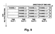
- Fig. 9 shows a state of assigning channels by the PDMA method which is applied to portable telephones and the like.
- a spatial division of a single time slot in the same frequency is made and data is transmitted for a plurality of users.
- an axis of abscissa represents a time axis and an axis of ordinate represents a spatial direction (a bus multiple direction).
- Division of four slots (time slots 1 to 4) in the same frequency is made in a direction of the time axis, and each of the four slots is further divided into four busses which are different in spatial directions.
- the time slot 3 is divided into four channels, namely, a channel 3.1 (a first bus in the time slot 3), a channel 3.2 (a second bus in the time slot 3), a channel 3.3 (a third bus in the time slot 3), and a channel 3.4 (a fourth bus in the time slot 3).
- a channel 3.1 a first bus in the time slot 3
- a channel 3.2 a second bus in the time slot 3
- a channel 3.3 a third bus in the time slot 3
- a channel 3.4 a fourth bus in the time slot 3.
- Different users are assigned to the channels, respectively.
- the four channels in the same time slot are separated using a signal extracting device, such as, an adaptive array and the like which has directivity.
- a fundamental principle of an adaptive array is that radio waves from different directions are received by a plurality of antennas and signals received from each of the antennas are weighted to differentiate signals from different users.
- Fig. 10 shows the constitution of a conventional receiving system for PDMA.
- four antennas 3 to 6 are provided so as to separate a user 1 and a user 2, and a frequency conversion is applied to an output of each antenna by a local oscillation signal Lo in a frequency conversion circuit 7.
- Each received signal which has been subjected to frequency conversion is further converted into a digital signal by an A/D converter 8 and sent to a DSP (digital signal processor) 10.
- DSP digital signal processor
- Adaptive arrays 11 and 12, a received signal vector calculator 13, a memory 14, a correlation value calculator 15, and a channel assigning device 16 are built in the DSP 10.
- the adaptive arrays 11 and 12 extract only specified user signals, which are designated by the channel assigning device 16, out of received digital signals, respectively. More specifically, the adaptive array 11 extracts a received signal of the user 1 and the adaptive array 12 extracts a received signal of the user 2.
- the received signal vector calculator 13 calculates received signal vectors applicable to all the users based on the received digital signals and output signals of the adaptive arrays 11 and 12, and the received signal vector calculator 13 stores the received signal vectors in the memory 14.
- the channel assigning device 16 designates the two users (the user 1 and the user 2) for the memory 14 and the correlation value calculator 15.
- the correlation value calculator 15 calculates a mutual correlation value of the received signal vectors of the two designated users among from the received signal vectors stored in the memory 14.
- the channel assigning device 16 receives the calculated mutual correlation value of the received signal vectors of the two users, and then, if the mutual correlation value is a fixed value or less, the channel assigning device 16 assigns the two users to the same time slot for multiplexing.
- the same time slot can be assigned to a plurality of users, the assignment is only performed when a difference in strength of receiving power of signals received from a plurality of users is less than a certain fixed value because, it will be difficult to demodulate both of the signals under the fixed gain condition when there is a big difference in the power of the two received signals.
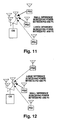
- Figs. 11 and 12 show typical conventional assignment of time slots.
- communication is taking place between a base station CS and user terminals PS1 and PS2 (assuming the communication is taking place in different time slots), and an additional user terminal PS3 initiates a new call.
- the difference between receiving power of PS1 and PS2 and receiving power of PS3 is calculated. If the difference in receiving power between PS1 and PS3 is greater than the difference in receiving power between PS2 and PS3, the base station CS assigns the new user terminal PS3 to the time slot of PS2 because the difference in receiving power is smaller, and carries out multiplexing of both PS2 and PS3 in that time slot.
- Fig. 11 and 12 show typical conventional assignment of time slots.
- communication is taking place between a base station CS and user terminals PS1 and PS2 (assuming the communication is taking place in different time slots), and an additional user terminal PS3 initiates a new call.
- the difference between receiving power of PS1 and PS2 and receiving power of PS3 is calculated. If the difference in receiving power between PS1
- the base station CS assigns the new user terminal PS3 to the time slot of PS1, and carries out multiplexing of both PS1 and PS3 in that time slot.
- a plurality of interference cancellers each of which comprises an adaptive array, a parameter estimating device for estimating how much signal components of a user are contained in a signal, and an arithmetic unit which removes interference signal components by extracting from input signals signal components of all the users other than a certain user, are connected in series and at a plurality of stages.
- the ratio of signal components of other users contained in user signals to the user signals is decreased step by step at each stage, and finally the user signals are completely separated and extracted from user to user.
- a signal of any one of the users can normally be demodulated at a certain stage, and the signal of the user normally demodulated is removed from received signals and outputted to a canceller of the next stage.
- a MIC a multiple stage interference canceller
- the present invention was made in consideration of the above problems and advantageously provides a device and method in which signals are received from a plurality of users using a plurality of antennas which is able to reliably separate signals from different users and communicate with the plurality of users.
- the present invention is a radio receiving system which receives signals from a plurality of users using a plurality of antennas.
- the present invention is characterized in that it has channel assignment information generating means for generating channel assignment information as to user signals to be extracted and extraction means for extracting each user signal from signals received by the plurality of antennas, based on the channel assignment information, and the channel assignment information generating means generate the channel assignment information to be extracted so as to create a difference in receiving power between respective users and supply the channel assignment information to the extraction means.
- the receiving power of signals from respective users is different, at least any one of the user signals can securely be separated and extracted, even when it is not possible to separate and extract all the user signals. Therefore, it is possible to remove the user signal securely separated and extracted from a plurality of user signals received by the plurality of antennas.
- the channel assignment information generating means generate the channel assignment information to be extracted and supply the channel assignment information to the extraction means to ensure that at least one of the differences in receiving power among the respective users exceeds the specified value.
- the specified value may be a fixed value, for example 10dB, or may be a variable or adjustable value. It is also possible to determine the specified value according to an allowable error rate.
- the extraction means are constituted in such a manner that a plurality of extraction units for extracting the user signals from user to user are connected in series, and the extraction unit extracts at least any one of the user signals, removes the extracted user signal from input signals received and supplies the extracted user signal to the extraction unit of the next stage. If a plurality of extraction units are connected in series to constitute the MIC, there will be a difference in receiving power between the respective users at each stage, at each extraction unit. Thus, any one of the signals (a signal having the greatest receiving power) can securely be separated and extracted, whereby it is possible to effectively demonstrate an interference removing function at each extraction unit.
- the channel assignment information generating means generate channel assignment information multiplexed by the PDMA method
- the extraction means can extract each user signal from the user signals multiplexed by the PDMA method.
- the channel assignment information generating means update the channel assignment information at intervals of a certain period of time.
- the most suitable channel assignment information can always be generated and stable communication with a plurality of users can be established and maintained.
- the present invention provides a method of receiving signals from a plurality of users using a plurality of antennas.
- This method is characterized by including an assignment step of assigning a plurality of user signals to the same time slot in order for differences in receiving power among the users to arise and a separation step of separating the user signals, which are assigned to the same time slot, from the received signals.
- the plurality of users are assigned to the same time slot in order for at least any one of the differences in receiving power to exceed a specified value.
- the user signals assigned to the same time slot are separated from the received signals and demodulated one at a time, and the user signals demodulated are removed from the received signals one at a time.
- the assignment step can be repeated at a specified interval.
- this method it is also possible to have further a step of controlling transmitting power of a user terminal in order for the differences in receiving power to arise.
- This method can be preferably applied to radio reception using PDMA.
- FIG. 1 shows the constitution of a receiving system using MIC.
- Four antennas 3 - 6, a frequency converter 7, and an A/D converter 8 are provided, and an input signal vector X1(t) output from the A/D converter 8 is sent to an arithmetic unit 101 at the first stage, adaptive arrays AA11 - AAm1 at the first stage, and parameter estimating devices PE11 - PEm1 at the first stage.
- User signals Y11 - Ym1 which are complex signals containing corresponding user signal components are output from the adaptive arrays AA11 - AAm1, respectively.
- the user signals Y11 - Ym1 are sent to the arithmetic unit at the first stage and are detected (demodulated) by corresponding detectors (demodulators) DE11 - DEm1.
- the parameter estimating devices PE11 - PEm1 Based on the input vector signal X1(t) and detected outputs (demodulated outputs), the parameter estimating devices PE11 - PEm1 estimate received signal coefficient vectors H11 - Hm1 and send the estimated values to the arithmetic device 101 at the first stage.
- the parameter estimating devices PE11 - PEm1 estimate how much the corresponding user signal components are contained in input signal vectors, how much the corresponding user signal components make phase rotations with respect to the input signal vectors.
- the arithmetic device 101 calculates input signals X12(t) - Xm2(t) from user to user and send the input signals to adaptive arrays AA12 - AAm2 of the second stage.
- Operations of the adaptive arrays, parameter estimating devices, detectors, arithmetic devices of the second stage are same as the operations of those of the first stage, and all the user signal components excluding the user i are removed at each of the stages.
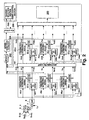
- Fig. 2 shows the constitution of a radio receiving system according to this embodiment.
- the method of assigning a channel is different in the present embodiment. More specifically, in the present embodiment is provided a memory 202 for storing a received signal coefficient H of a user signal from a parameter estimating device PE at each stage, a received signal power calculator 204 for calculating receiving the power of each user signal based on the stored received signal coefficient, a DPRAM 206 which stores the calculated received signal power, and a channel selecting section 208 for determining the channel assignment based on the received signal power.
- a memory 202 for storing a received signal coefficient H of a user signal from a parameter estimating device PE at each stage, a received signal power calculator 204 for calculating receiving the power of each user signal based on the stored received signal coefficient, a DPRAM 206 which stores the calculated received signal power, and a channel selecting section 208 for determining the channel assignment based on the received signal power.
- a memory 202 for storing a received signal coefficient H of
- the system is configured such that user signals with relatively large differences in received power are assigned to the same time slot, and instructions are given to an adaptive array of each stage.
- Channel assignment information determined by the channel selection section 208 is supplied to an adaptive array of each stage and a user signal designated is extracted by the adaptive array of each stage.
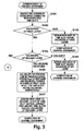
- Fig. 3 shows an assignment processing flowchart at the channel selection section 208 which functions as channel assignment information generating means.
- S101 the number of users connected to each time slot is confirmed.
- the number of users presently assigned to each of four time slots is confirmed.
- S102 While focusing on a first layer, namely, a first direction of the bus multiple direction, it is judged whether or not any vacant slots are available (S102). If there is a vacancy at the first layer, a time slot having a vacancy at the first layer will be assigned to a user newly initiating a call (S103). In other words, if possible, each of a plurality of users will be assigned a different time slot.
- the time slots at the first layer have already been occupied and therefore no vacant slots are available, it will next be judged whether or not there is a vacancy at the second layer (S104). If there is a single time slot having a vacancy, in accordance with an algorithm which assigns a plurality of users to different time slots as much as possible, a user initiating a new call will be assigned to a time slot having a vacancy (S105). If there are two or more time slots having a vacancy at the second layer, it will be determined in which of the two time slots having a vacancy assignment is preferable, based on the received power calculated by the received signal power calculator 204.
- differences Pdiff between receiving power P of users who have already been assigned to the first layer of time slots which have a vacancy at the second layer and receiving power Pnew of a user initiating a new call are calculated (S106). For example, if a second time slot and a third time slot have vacancies at the second layer are and a user 2 and a user 3 have already been assigned to the first layer of each of the second and third time slots, a difference P2-Pnew between receiving power P2 of user 2 and the receiving power Pnew of the new user and a difference P3-Pnew between receiving power P3 of user 3 and the receiving power Pnew of the new user will be calculated.
- the second layer of the time slot in which the Pdiff is largest namely the time slot in which the difference in receiving power between the respective two users is largest, is selected and the new user is assigned to the time slot selected (S107).
- the new user will be assigned to the second layer of the third time slot to which user 3 has been assigned.
- the new user is assigned to a time slot in which the difference in receiving power is large and user signals are distinguished in the time slot, it will be easy to demodulate the signal having large receiving power. Therefore, at least one large received signal can be reliably demodulated at each MIC stage, and it will be possible to remove interference components from input signals using these user signals.
- the channel selection section 208 will assign slots according to the process of Fig. 4. More specifically, a parameter N which represents a layer is set to 3 (S201) and it is judged whether or not there is any time slot whose Nth layer (namely, the third layer) is vacant (S202). If there is a single time slot which has a vacancy at the third layer, similarly to the processes S104 and S105 at the second layer, the new user is assigned to the time slot concerned having a vacancy at the third layer according to the algorithm which assigns users to different time slots to the extent possible (S203).
- the differences Pidiff between receiving power Pnew of the new user and receiving power Pi of users who are assigned to the first layer and the second layer of all the time slots having a vacancy at the third layer will be calculated (S204). For example, if there is a vacancy at the third layer of the second and third time slots, the users 1 and 2 are assigned to the first and second layers of the second time slot, respectively, the users 3 and 4 are assigned to the first and second layers of the third time slot, and P1-Pnew, P2-Pnew, P3-Pnew, and P4-Pnew are calculated.
- the specified value may be 10dB, for example. If a time slot in which the differences in receiving power among all the users assigned exceed the specified value is found, the new user is assigned to that time slot (S206). For example, if both of P1-Pnew and P2-Pnew exceed the specified value in the second time slot, the new user will be assigned to the second time slot.
- any one of the user signals (a signal having the largest receiving power) can be securely and reliably demodulated and extracted from the input signals, and signals to be sent to the next stage can be generated. Further, if there is no slot in which the differences in receiving power of all users exceeds the specified value, the time slot having the greatest number of users who exceed the specified value will be selected and the new user will be assigned to the time slot (S207).
- the new user will be assigned to the third time slot.
- the time slot to which the new user is assigned at least the receiving power of any one of the users exceeds the specified value and is larger than the receiving power of the other users. Therefore, the user signal is demodulated and extracted from input signals, whereby it is possible to generate a signal to be sent to the next stage of the MIC.
- the differences in receiving power among all the users are the specified value or less in all the time slots which have a vacancy at the third layer, the new user will be assigned to a random time slot which has a vacancy at the third layer.
- the third layer is the final layer (S208).
- the number of layers which can be multiplexed is determined according to the number of antennas . For example, if a certain time slot can be multiplexed, up to four layers as shown in Fig. 9, N will be increased by one because the present layer is not the final layer (S209), and the processes including and subsequent to S202 will be repeated. Thus, the new user is assigned to the fourth layer of any one of the time slots. However, if it is determined that the present layer is the final layer, it is determined that the new user cannot be assigned, channel assignment is rejected (S210), and the process is completed.
- the channel assignment information generated by the processes described above is supplied to an adaptive array of each stage, as already described.
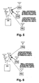
- Figs. 5 and 6 typically show an assignment process according to this embodiment.
- PS1-PS3 When the new user terminal PS3 initiates a call as shown in Fig. 5 and PS1-PS3 is larger than PS2-PS3 in the difference of receiving power, not PS2, but PS1 and PS3 will be assigned to the same time slot. Further, if PS1-PS3 is smaller than PS2-PS3 in the difference of receiving power as shown in Fig. 6, PS3 will be assigned to the time slot of the PS2 and multiplexing will be applied to the same time slot. It is noted that a comparison with a conventional assignment process shown in Figs. 11 and 12 should be made.
- the users 3 and 4 are assigned to the third time slot, there are no vacancies at the first and second layers of the third time slot, and only a user 5 is assigned to the fourth time slot and there is a vacancy at the second layer of the fourth time slot, when a new user 6 calls, if the differences in receiving power between the new user 6 and the respective users 1 and 2 exceed the specified value and if the difference in receiving power between user 5 and the new user 6 is the specified value or less in the fourth time slot which has a vacancy at the second layer, the new user 6 will be assigned not to the fourth time slot, but to the second time slot.
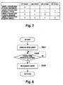
- Fig. 7 shows a state of demodulation at each stage of the MIC in such a case that new users are assigned according to the algorithm of this embodiment. It is assumed that users 1 - 4 are assigned to a certain time slot and receiving power is large in order of the users 1 - 4.
- a reference symbol ⁇ represents that demodulation is performed without any error
- a reference symbol ⁇ represents that a demodulation error arises.
- a signal of user 1 whose receiving power is largest is normally demodulated and demodulation errors occur to signals of the other users 2 - 4.
- the signal of user 1 which is normally demodulated By extracting from input signals the signal of user 1 which is normally demodulated, the signal of user 1 which is contained in the input signals is removed and becomes signal input at the next stage of MIC.
- the signal of user 1 has already been removed and a signal of user 2 has the largest receiving power and is normally demodulated.
- the signal of user 2 normally demodulated is extracted from the input signals, and the input signals which do not contain the signal of the user 2 as an interference component are sent to the next stage.
- the signal components of users 1 and 2 have already been removed, and the signal user 3, which is now the strongest, is demodulated without any error.
- the signal of the user 3 is the extracted from the input signals and the input signals which contain components of only the signal of user 4 are sent to the next stage.
- the present invention is not limited to the above configuration, and it is possible to make various modifications within the technical idea of the present invention. For example, because it is possible that after a new user is assigned to a time slot based on the algorithm (1) or (2) described above, the location and receiving power of a user terminal will change, it is also preferable to employ a dynamic change of assignment of a user to a time slot.
- Fig. 8 is a flowchart of assignment processing in such a case.
- a new user is assigned to a time slot (S301). It is then judged whether or not a certain period of time has elapsed subsequent to assignment (S302). It the set amount of time has passed, differences in receiving power among all the users being in communication are recalculated, and, if necessary, the new user is reassigned to a time slot which will result in sufficiently large differences in receiving power (S303).
- assignment of first layer users is left unchanged, the differences in receiving power among users at the second layer and the subsequent layers is calculated, and the users at the first stage are reassigned to the second layer and subsequent layers so as to ensure sufficiently large differences in receiving power.
- a difference in receiving power between a new user and an existing user is a specified value or less and the difference in receiving power is relatively small, the new user will not be assigned to a random time slot, but the difference in receiving power will be enhanced by controlling the receiving power of the users itself.
- a power control section is newly installed in the constitution of Fig. 2, and, if the difference between the new user and the existing user is less than or equal to the specified value, a power control signal will be transmitted from the power control section to a new user terminal, transmission power of the new user terminal will be increased or decreased, and the difference in receiving power between the new user and the existing user will be made larger.
- each stage of MIC can be made to function more effectively.
- a signal of each user is securely separated from received signals in which a plurality of user signals are contained, and thus communication with a plurality of users can be performed simultaneously.
Landscapes
- Engineering & Computer Science (AREA)
- Computer Networks & Wireless Communication (AREA)
- Signal Processing (AREA)
- Mobile Radio Communication Systems (AREA)
- Radio Transmission System (AREA)
Abstract
A radio receiving system has a plurality of interference
cancelers. Received signals are separated and demodulated by an
adaptive array (AA), a parameter estimating section (PE), and a
detector (DE) of each of the interference cancelers into the signals
of the respective users and outputted from a processing circuit
(200) lastly. A demodulated signal demodulated without any
demodulation error is removed from the received signals, the
interference due to the user signal is removed, and the resultant
received signals are sent to the next interference canceler. Users
are assigned to the same time slot in such a way that the difference
between the reception powers of the user signals are as large as
possible. Thus at least one of the user signals is demodulated
without any error by each interference canceler and removed from
the received signals. Therefore, the signal of each user can be
extracted reliably by this radio receiving system of the PDMA method.
Description
The present invention relates to a radio receiving system
and method, particularly to a technology of removing interference
signals of other users in receiving radios by a communication method,
such as a PDMA (Path Division Multiple Access) and the like.
Heretofore, a technology of assigning and multiplexing a
plurality of channels in the same frequency has been known.
Fig. 9 shows a state of assigning channels by the PDMA method
which is applied to portable telephones and the like. In the PDMA
method, a spatial division of a single time slot in the same frequency
is made and data is transmitted for a plurality of users. In the
drawing, an axis of abscissa represents a time axis and an axis
of ordinate represents a spatial direction (a bus multiple
direction). Division of four slots (time slots 1 to 4) in the same
frequency is made in a direction of the time axis, and each of the
four slots is further divided into four busses which are different
in spatial directions. Referring to a time slot 3 for example,
the time slot 3 is divided into four channels, namely, a channel
3.1 (a first bus in the time slot 3), a channel 3.2 (a second bus
in the time slot 3), a channel 3.3 (a third bus in the time slot
3), and a channel 3.4 (a fourth bus in the time slot 3). Different
users are assigned to the channels, respectively. The four channels
in the same time slot are separated using a signal extracting device,
such as, an adaptive array and the like which has directivity. A
fundamental principle of an adaptive array is that radio waves from
different directions are received by a plurality of antennas and
signals received from each of the antennas are weighted to
differentiate signals from different users.
Fig. 10 shows the constitution of a conventional receiving
system for PDMA. In the drawing, four antennas 3 to 6 are provided
so as to separate a user 1 and a user 2, and a frequency conversion
is applied to an output of each antenna by a local oscillation signal
Lo in a frequency conversion circuit 7. Each received signal which
has been subjected to frequency conversion is further converted
into a digital signal by an A/D converter 8 and sent to a DSP (digital
signal processor) 10.
As described above, although the same time slot can be assigned
to a plurality of users, the assignment is only performed when
a difference in strength of receiving power of signals received
from a plurality of users is less than a certain fixed value because,
it will be difficult to demodulate both of the signals under the
fixed gain condition when there is a big difference in the power
of the two received signals.
Figs. 11 and 12 show typical conventional assignment of time
slots. In the illustrated example, communication is taking place
between a base station CS and user terminals PS1 and PS2 (assuming
the communication is taking place in different time slots), and
an additional user terminal PS3 initiates a new call. As shown
in Fig. 11, the difference between receiving power of PS1 and PS2
and receiving power of PS3 is calculated. If the difference in
receiving power between PS1 and PS3 is greater than the difference
in receiving power between PS2 and PS3, the base station CS assigns
the new user terminal PS3 to the time slot of PS2 because the
difference in receiving power is smaller, and carries out
multiplexing of both PS2 and PS3 in that time slot. On the other
hand, as shown in Fig. 12, if the difference in receiving power
between PS1 and PS3 is smaller than the difference in receiving
power between PS2 and PS3, the base station CS assigns the new user
terminal PS3 to the time slot of PS1, and carries out multiplexing
of both PS1 and PS3 in that time slot.
As described above, heretofore a plurality of users whose
mutual correlation values or differences of receiving power strength
are a fixed value or less have been assigned to the same time slot
and a received signal of each user has been separated and extracted
by an adaptive array. However, as shown in Fig.11, for example,
when PS2 and PS3 are assigned to the same time slot and PS2 and
PS3 transmit signals from almost identical directions, the adaptive
array cannot separate the signals, and separation of just PS2 or
PS3 is impossible. This is a problem.
In response, the present applicant developed the radio
receiving system described in Japanese Patent Application No. Hei
11-290093. In that system, a plurality of interference cancellers
each of which comprises an adaptive array, a parameter estimating
device for estimating how much signal components of a user are
contained in a signal, and an arithmetic unit which removes
interference signal components by extracting from input signals
signal components of all the users other than a certain user, are
connected in series and at a plurality of stages. The ratio of
signal components of other users contained in user signals to the
user signals is decreased step by step at each stage, and finally
the user signals are completely separated and extracted from user
to user.
In such a configuration in which interference cancellers are
connected in series and at a plurality of stages (hereinafter called
as a MIC, a multiple stage interference canceller), a signal of
any one of the users can normally be demodulated at a certain stage,
and the signal of the user normally demodulated is removed from
received signals and outputted to a canceller of the next stage.
Thus, it is necessary to demodulate at least one of the user signals
without any error at each stage.
However, if users transmitting singles of similar strength
are assigned to the same time slot, as commonly occurs with MIC,
it will be possible to normally demodulate all the user signals
at a certain stage. On the other hand, it will be possible to fail
in demodulation of all the user signals. Thus, the full
functionality of MIC cannot always be realized. In other words,
if the constitution is such that a single stage is provided, it
is necessary to simultaneously separate all users, and such
assignment should be prioritized such that all user signals can
be normally be demodulated. However, if the constitution is such
that a plurality of stages are provided as in MIC, when a demodulation
error occurs to all the user signals as a result of such assignment,
interference cannot be sequentially canceled. Thus, there has been
such a problem that it is difficult to separate signals from user
to user.
The present invention was made in consideration of the above
problems and advantageously provides a device and method in which
signals are received from a plurality of users using a plurality
of antennas which is able to reliably separate signals from
different users and communicate with the plurality of users.
The present invention is a radio receiving system which
receives signals from a plurality of users using a plurality of
antennas. The present invention is characterized in that it has
channel assignment information generating means for generating
channel assignment information as to user signals to be extracted
and extraction means for extracting each user signal from signals
received by the plurality of antennas, based on the channel
assignment information, and the channel assignment information
generating means generate the channel assignment information to
be extracted so as to create a difference in receiving power between
respective users and supply the channel assignment information to
the extraction means. When a the receiving power of signals from
respective users is different, at least any one of the user signals
can securely be separated and extracted, even when it is not possible
to separate and extract all the user signals. Therefore, it is
possible to remove the user signal securely separated and extracted
from a plurality of user signals received by the plurality of
antennas.
Here, it may be preferable that the channel assignment
information generating means generate the channel assignment
information to be extracted and supply the channel assignment
information to the extraction means to ensure that at least one
of the differences in receiving power among the respective users
exceeds the specified value. By creating a sufficiently wide
difference in receiving power which exceeds the specified value,
at least one of the user signals (the signal having the greatest
receiving power) can securely be separated and extracted. The
specified value may be a fixed value, for example 10dB, or may be
a variable or adjustable value. It is also possible to determine
the specified value according to an allowable error rate.
It may further be preferable that the extraction means are
constituted in such a manner that a plurality of extraction units
for extracting the user signals from user to user are connected
in series, and the extraction unit extracts at least any one of
the user signals, removes the extracted user signal from input
signals received and supplies the extracted user signal to the
extraction unit of the next stage. If a plurality of extraction
units are connected in series to constitute the MIC, there will
be a difference in receiving power between the respective users
at each stage, at each extraction unit. Thus, any one of the signals
(a signal having the greatest receiving power) can securely be
separated and extracted, whereby it is possible to effectively
demonstrate an interference removing function at each extraction
unit.
In one aspect of the present invention, the channel assignment
information generating means generate channel assignment
information multiplexed by the PDMA method, and the extraction means
can extract each user signal from the user signals multiplexed by
the PDMA method.
Further, it may also be preferable that in this system, the
channel assignment information generating means update the channel
assignment information at intervals of a certain period of time.
Thus, the most suitable channel assignment information can always
be generated and stable communication with a plurality of users
can be established and maintained.
Further, in this system, it is possible to provide means for
controlling transmitting power at a user terminal in order to ensure
a difference in receiving power between the respective channels.
Thus, when there is at first no difference in receiving power, it
is possible to generate a difference in receiving power, such that
suitable channel assignment information can in turn be generated.
Further, the present invention provides a method of receiving
signals from a plurality of users using a plurality of antennas.
This method is characterized by including an assignment step of
assigning a plurality of user signals to the same time slot in order
for differences in receiving power among the users to arise and
a separation step of separating the user signals, which are assigned
to the same time slot, from the received signals.
It may be preferable that, at the assignment step, the plurality
of users are assigned to the same time slot in order for at least
any one of the differences in receiving power to exceed a specified
value.
Further, it is preferable that at the assignment step, if
there are a plurality of time slots which can be assigned, a plurality
of user signals are assigned to the same time slot in order to enhance
the differences in receiving power.
In this method, it is preferable that at the separation step,
the user signals assigned to the same time slot are separated from
the received signals and demodulated one at a time, and the user
signals demodulated are removed from the received signals one at
a time.
In this method, the assignment step can be repeated at a
specified interval.
Further, in this method, it is also possible to have further
a step of controlling transmitting power of a user terminal in order
for the differences in receiving power to arise.
This method can be preferably applied to radio reception using
PDMA.
In the following, a preferred embodiment of the present
invention will be described with reference to the accompanying
drawings.
A receiving system using MIC will be described as an example
of application of the present invention. Fig. 1 shows the
constitution of a receiving system using MIC. Four antennas 3 - 6,
a frequency converter 7, and an A/D converter 8 are provided,
and an input signal vector X1(t) output from the A/D converter 8
is sent to an arithmetic unit 101 at the first stage, adaptive arrays
AA11 - AAm1 at the first stage, and parameter estimating devices
PE11 - PEm1 at the first stage.
User signals Y11 - Ym1 which are complex signals containing
corresponding user signal components are output from the adaptive
arrays AA11 - AAm1, respectively. The user signals Y11 - Ym1 are
sent to the arithmetic unit at the first stage and are detected
(demodulated) by corresponding detectors (demodulators) DE11 - DEm1.
Based on the input vector signal X1(t) and detected outputs
(demodulated outputs), the parameter estimating devices PE11 - PEm1
estimate received signal coefficient vectors H11 - Hm1 and send
the estimated values to the arithmetic device 101 at the first stage.
The parameter estimating devices PE11 - PEm1 estimate how much the
corresponding user signal components are contained in input signal
vectors, how much the corresponding user signal components make
phase rotations with respect to the input signal vectors.
The arithmetic device 101 at the first stage removes
interference signal components for every user i (i=1 - m) by
extracting all the user signal components excluding the user i from
the input signal vector X1(t), and calculates and outputs an input
signal vector Xi2(t) of the user i. However, if a demodulation
error arises at the demodulators DE11 - DEm1, the signals will not
be removed as the interference signal components from the input
signal vectors. If interference components are removed using
signals to which a demodulation error occurred, the demodulation
error will directly influence on input signals of the next stage.
The arithmetic device 101 calculates input signals X12(t) - Xm2(t)
from user to user and send the input signals to adaptive arrays
AA12 - AAm2 of the second stage.
Operations of the adaptive arrays, parameter estimating
devices, detectors, arithmetic devices of the second stage are same
as the operations of those of the first stage, and all the user
signal components excluding the user i are removed at each of the
stages.
Therefore, other user signal components are fully removed
from input signals X1(L+1)(t) - Xm(L+1)(t) which have passed an
arithmetic device 10L of the Lth stage, and it is possible to separate
and output the input signals X1(L+1)(t) - Xm(L+1)(t) from user to
user by a separation section 200 which is composed of the last adaptive
array and detector.
With regard to user signals normally demodulated without any
demodulation error, because cancellation of interference
components is no longer necessary, the signals need not be sent
to a canceller at the next stage. For example in Fig. 1, when signals
of a user 1 are separated, it will be sufficient if the arithmetic
device 101 does not output the input signal X12(t), but outputs
input signals X22(t) - Xm2(t) to adaptive arrays of the next stage
and removes the interference components from the input signals one
after another.
As described above, when user signals differing only slightly
in receiving power are assigned to the same time slot, when a
demodulation error occurs to all the user signals in the canceller
of the first stage, signals to be sent to the next stage cannot
be generated and signals from different users cannot be separated.
Thus, in this embodiment, on the assumption that such an MIC
constitution is employed, it is possible to securely separate a
signal of each user by further adjusting the user assignment.
Fig. 2 shows the constitution of a radio receiving system
according to this embodiment. Although the constitution is
fundamentally similar to that of Fig. 1, the method of assigning
a channel is different in the present embodiment. More specifically,
in the present embodiment is provided a memory 202 for storing a
received signal coefficient H of a user signal from a parameter
estimating device PE at each stage, a received signal power
calculator 204 for calculating receiving the power of each user
signal based on the stored received signal coefficient, a DPRAM
206 which stores the calculated received signal power, and a channel
selecting section 208 for determining the channel assignment based
on the received signal power. Unlike conventional systems, user
signals whose receiving powers are similar are not assigned to the
same time slot. Rather, the system is configured such that user
signals with relatively large differences in received power are
assigned to the same time slot, and instructions are given to an
adaptive array of each stage. The received signal power calculator
204 can calculate the receiving power of each user according to
the formula P=H2, based on each received signal coefficient H.
Channel assignment information determined by the channel selection
section 208 is supplied to an adaptive array of each stage and a
user signal designated is extracted by the adaptive array of each
stage.
Fig. 3 shows an assignment processing flowchart at the channel
selection section 208 which functions as channel assignment
information generating means. First, the number of users connected
to each time slot is confirmed (S101). In the case of the
constitution shown in Fig. 9, the number of users presently assigned
to each of four time slots is confirmed. While focusing on a first
layer, namely, a first direction of the bus multiple direction,
it is judged whether or not any vacant slots are available (S102).
If there is a vacancy at the first layer, a time slot having a vacancy
at the first layer will be assigned to a user newly initiating a
call (S103). In other words, if possible, each of a plurality of
users will be assigned a different time slot. If, however, the
time slots at the first layer have already been occupied and therefore
no vacant slots are available, it will next be judged whether or
not there is a vacancy at the second layer (S104). If there is
a single time slot having a vacancy, in accordance with an algorithm
which assigns a plurality of users to different time slots as much
as possible, a user initiating a new call will be assigned to a
time slot having a vacancy (S105). If there are two or more time
slots having a vacancy at the second layer, it will be determined
in which of the two time slots having a vacancy assignment is
preferable, based on the received power calculated by the received
signal power calculator 204. More specifically, differences Pdiff
between receiving power P of users who have already been assigned
to the first layer of time slots which have a vacancy at the second
layer and receiving power Pnew of a user initiating a new call are
calculated (S106). For example, if a second time slot and a third
time slot have vacancies at the second layer are and a user 2 and
a user 3 have already been assigned to the first layer of each of
the second and third time slots, a difference P2-Pnew between
receiving power P2 of user 2 and the receiving power Pnew of the
new user and a difference P3-Pnew between receiving power P3 of
user 3 and the receiving power Pnew of the new user will be calculated.
Among the time slots which have a vacancy at the second layer, the
second layer of the time slot in which the Pdiff is largest, namely
the time slot in which the difference in receiving power between
the respective two users is largest, is selected and the new user
is assigned to the time slot selected (S107). In the above example,
becauseP2-Pnew is smaller than P3-Pnew, the new user will be assigned
to the second layer of the third time slot to which user 3 has been
assigned.
If the new user is assigned to a time slot in which the difference
in receiving power is large and user signals are distinguished in
the time slot, it will be easy to demodulate the signal having large
receiving power. Therefore, at least one large received signal
can be reliably demodulated at each MIC stage, and it will be possible
to remove interference components from input signals using these
user signals.
When, on the other hand, there is no vacancy at the second
layer in all the time slots, the channel selection section 208 will
assign slots according to the process of Fig. 4. More specifically,
a parameter N which represents a layer is set to 3 (S201) and it
is judged whether or not there is any time slot whose Nth layer
(namely, the third layer) is vacant (S202). If there is a single
time slot which has a vacancy at the third layer, similarly to the
processes S104 and S105 at the second layer, the new user is assigned
to the time slot concerned having a vacancy at the third layer
according to the algorithm which assigns users to different time
slots to the extent possible (S203).
On the other hand, if there are two or more time slots which
have a vacancy at the third layer, the differences Pidiff between
receiving power Pnew of the new user and receiving power Pi of users
who are assigned to the first layer and the second layer of all
the time slots having a vacancy at the third layer will be calculated
(S204). For example, if there is a vacancy at the third layer of
the second and third time slots, the users 1 and 2 are assigned
to the first and second layers of the second time slot, respectively,
the users 3 and 4 are assigned to the first and second layers of
the third time slot, and P1-Pnew, P2-Pnew, P3-Pnew, and P4-Pnew
are calculated. It is then judged whether or not all the Pidiffs
exceed a specified value, in other words whether or not differences
in receiving power are sufficiently large (S205). The specified
value may be 10dB, for example. If a time slot in which the
differences in receiving power among all the users assigned exceed
the specified value is found, the new user is assigned to that time
slot (S206). For example, if both of P1-Pnew and P2-Pnew exceed
the specified value in the second time slot, the new user will be
assigned to the second time slot. In this manner, it is assured
that the receiving powers of user 1, user 2, and the new user will
sufficiently differ from each other, whereby at each stage of the
MIC, any one of the user signals (a signal having the largest receiving
power) can be securely and reliably demodulated and extracted from
the input signals, and signals to be sent to the next stage can
be generated. Further, if there is no slot in which the differences
in receiving power of all users exceeds the specified value, the
time slot having the greatest number of users who exceed the specified
value will be selected and the new user will be assigned to the
time slot (S207). For example, if both of the P1-Pnew and P2-Pnew
are less than the specified value in the second time slot, P3-Pnew
is the specified value or less, and the P4-Pnew exceeds the specified
value in the third time slot, the new user will be assigned to the
third time slot. Thus, in the time slot to which the new user is
assigned, at least the receiving power of any one of the users exceeds
the specified value and is larger than the receiving power of the
other users. Therefore, the user signal is demodulated and
extracted from input signals, whereby it is possible to generate
a signal to be sent to the next stage of the MIC. When the differences
in receiving power among all the users are the specified value or
less in all the time slots which have a vacancy at the third layer,
the new user will be assigned to a random time slot which has a
vacancy at the third layer.
On the other hand, if there are no time slots having a vacancy
at the third layer, it will be judged whether or not the third layer
is the final layer (S208). The number of layers which can be
multiplexed is determined according to the number of antennas . For
example, if a certain time slot can be multiplexed, up to four layers
as shown in Fig. 9, N will be increased by one because the present
layer is not the final layer (S209), and the processes including
and subsequent to S202 will be repeated. Thus, the new user is
assigned to the fourth layer of any one of the time slots. However,
if it is determined that the present layer is the final layer, it
is determined that the new user cannot be assigned, channel
assignment is rejected (S210), and the process is completed. The
channel assignment information generated by the processes described
above is supplied to an adaptive array of each stage, as already
described.
Figs. 5 and 6 typically show an assignment process according
to this embodiment. When the new user terminal PS3 initiates a
call as shown in Fig. 5 and PS1-PS3 is larger than PS2-PS3 in the
difference of receiving power, not PS2, but PS1 and PS3 will be
assigned to the same time slot. Further, if PS1-PS3 is smaller
than PS2-PS3 in the difference of receiving power as shown in Fig.
6, PS3 will be assigned to the time slot of the PS2 and multiplexing
will be applied to the same time slot. It is noted that a comparison
with a conventional assignment process shown in Figs. 11 and 12
should be made.
It should be noted that, in the assignment process according
to this embodiment, users are assigned to different time slots to
the extent possible, and therefore multiplicity of each time slot
is decreased. However, it is also possible to assign slots by
prioritizing the size of differences in receiving power. More
specifically, if there is a single time slot which has a vacancy
at the second layer, the new user will not be assigned to the time
slot and regardless of vacancy at the second layer, the new user
can also be assigned to the third layer of the time slot in which
the difference in receiving power is large. For example, even though
users 1 and 2 are assigned to the second time slot, the users 3
and 4 are assigned to the third time slot, there are no vacancies
at the first and second layers of the third time slot, and only
a user 5 is assigned to the fourth time slot and there is a vacancy
at the second layer of the fourth time slot, when a new user 6 calls,
if the differences in receiving power between the new user 6 and
the respective users 1 and 2 exceed the specified value and if the
difference in receiving power between user 5 and the new user 6
is the specified value or less in the fourth time slot which has
a vacancy at the second layer, the new user 6 will be assigned not
to the fourth time slot, but to the second time slot.
The following is a summary of an algorithm of the assignment
of new users.
Fig. 7 shows a state of demodulation at each stage of the
MIC in such a case that new users are assigned according to the
algorithm of this embodiment. It is assumed that users 1 - 4 are
assigned to a certain time slot and receiving power is large in
order of the users 1 - 4. In the drawing, a reference symbol ○
represents that demodulation is performed without any error, and
a reference symbol × represents that a demodulation error arises.
At the first stage of the MIC, a signal of user 1 whose receiving
power is largest is normally demodulated and demodulation errors
occur to signals of the other users 2 - 4. By extracting from input
signals the signal of user 1 which is normally demodulated, the
signal of user 1 which is contained in the input signals is removed
and becomes signal input at the next stage of MIC.
At the second MIC stage, the signal of user 1 has already
been removed and a signal of user 2 has the largest receiving power
and is normally demodulated. The signal of user 2 normally
demodulated is extracted from the input signals, and the input
signals which do not contain the signal of the user 2 as an
interference component are sent to the next stage.
At the third stage of MIC, signal components of users 1 and
2 have already been removed, and the signal user 3, which is now
the strongest, is demodulated without any error. The signal of
the user 3 is the extracted from the input signals and the input
signals which contain components of only the signal of user 4 are
sent to the next stage.
At the fourth stage of MIC, because, for practical purposes,
only the signal of user 4 is present (other signal components may
be present, but only to a negligible extent), it is possible to
easily extract and demodulate the signal of user 4.
As described above, because in this embodiment assignment
is made in a manner to ensure that the differences in receiving
power between a new user and existing users will be large when
multiplexing is applied to the same time slot, differences in
receiving power among assigned users assigned appear as shown in
Fig. 7. Thus, it is possible to securely demodulate at least one
of the user signals at each stage of MIC.
Although a preferred embodiment of the present invention is
described above, the present invention is not limited to the above
configuration, and it is possible to make various modifications
within the technical idea of the present invention. For example,
because it is possible that after a new user is assigned to a time
slot based on the algorithm (1) or (2) described above, the location
and receiving power of a user terminal will change, it is also
preferable to employ a dynamic change of assignment of a user to
a time slot.
Fig. 8 is a flowchart of assignment processing in such a case.
First, according to the algorithm (1) or (2), a new user is assigned
to a time slot (S301). It is then judged whether or not a certain
period of time has elapsed subsequent to assignment (S302). It
the set amount of time has passed, differences in receiving power
among all the users being in communication are recalculated, and,
if necessary, the new user is reassigned to a time slot which will
result in sufficiently large differences in receiving power (S303).
As an example, assignment of first layer users is left unchanged,
the differences in receiving power among users at the second layer
and the subsequent layers is calculated, and the users at the first
stage are reassigned to the second layer and subsequent layers so
as to ensure sufficiently large differences in receiving power.
Further, in the preferred embodiment, it may also be preferable
that, when a difference in receiving power between a new user and
an existing user is a specified value or less and the difference
in receiving power is relatively small, the new user will not be
assigned to a random time slot, but the difference in receiving
power will be enhanced by controlling the receiving power of the
users itself. For this purpose, for example, a power control section
is newly installed in the constitution of Fig. 2, and, if the
difference between the new user and the existing user is less than
or equal to the specified value, a power control signal will be
transmitted from the power control section to a new user terminal,
transmission power of the new user terminal will be increased or
decreased, and the difference in receiving power between the new
user and the existing user will be made larger. Thus, each stage
of MIC can be made to function more effectively.
As described above, according to the present invention, a
signal of each user is securely separated from received signals
in which a plurality of user signals are contained, and thus
communication with a plurality of users can be performed
simultaneously.
Claims (13)
- A radio receiving system which receives signals from a plurality of users using a plurality of antennas, the system comprising:wherein the channel assignment information generating means generate the channel assignment information to be extracted and supply the channel assignment information to the extraction means in such a manner as to ensure a difference in receiving power between user signals.channel assignment information generating means for generating channel assignment information concerning a user signal to be extracted; andextraction means for extracting a user signal of each user from received signals received by the plurality of antennas based on the channel assignment information,
- The radio receiving system according to claim 1, wherein the channel assignment information generating means generate channel assignment information to be extracted and supply the channel assignment information to the extraction means so that at least any one of the differences in receiving power among respective users exceeds a specified value.
- The radio receiving system according to any one of claims 1 and 2, wherein the extraction means are constituted in such a manner that a plurality of extraction units for extracting a user signal of each user are connected in series, and the extraction unit extracts at least one of the user signals, removes the extracted user signal from input signals, and supplies the signals from which the extracted user signal has been removed to the extraction unit for a next stage.
- The radio receiving system according to claim 3, wherein the channel assignment information generating means generate channel assignment information which is multiplexed by a PDMA method, and the extraction means extract a user signal of each user from user signals which are multiplexed by the PDMA method.
- The radio receiving system according to any one of claims 1 through 4, the channel assignment information generating means periodically update the channel assignment information at a set interval.
- The radio receiving system according to any one of claims 1 through 4 further comprising:means for controlling transmitting power of a user terminal to create a difference in receiving power between a plurality of channels.
- A method of receiving radio signals from a plurality of users using a plurality of antennas, the method comprising:an assignment step of assigning a plurality of user signals to an identical time slot to create differences in receiving power; anda separation step of separating the user signals assigned to the identical time slot from received signals.
- The radio receiving method according to claim 7, wherein, at the assignment step, the plurality of users are assigned to an identical time slot so that at least one of the differences in receiving power exceeds a specified value.
- The radio receiving method according to claim 7, wherein at the assignment step, when there exist a plurality of time slots which can be assigned, a plurality of user signals will be assigned to an identical time slot in such a manner that the differences in receiving power become larger.
- The radio receiving method according to any one of claims 7 through 9, wherein at the separation step, user signals assigned to the identical time slot are individually and sequentially separated from the received signals and demodulated at a plurality of stages, and the user signals demodulated are removed from the received signals one at a time.
- The radio receiving method according to any one of claims 7 through 10, wherein the assignment step is repeatedly performed at a specified interval.
- The radio receiving method according to any one of claims 7 through 10 further comprising:a step of controlling transmitting power of a user terminal in order to generate or enhance the differences in receiving power.
- The radio receiving method according to any one of claims 7 through 12, wherein the assignment step and the extraction step are carried out by a PDMA method.
Applications Claiming Priority (3)
| Application Number | Priority Date | Filing Date | Title |
|---|---|---|---|
| JP2000267199A JP3574057B2 (en) | 2000-09-04 | 2000-09-04 | Wireless receiving system and method |
| JP2000267199 | 2000-09-04 | ||
| PCT/JP2001/007263 WO2002021869A1 (en) | 2000-09-04 | 2001-08-24 | Radio receiving system and method |
Publications (2)
| Publication Number | Publication Date |
|---|---|
| EP1322128A1 true EP1322128A1 (en) | 2003-06-25 |
| EP1322128A4 EP1322128A4 (en) | 2009-11-18 |
Family
ID=18754158
Family Applications (1)
| Application Number | Title | Priority Date | Filing Date |
|---|---|---|---|
| EP01958471A Withdrawn EP1322128A4 (en) | 2000-09-04 | 2001-08-24 | Radio receiving system and method |
Country Status (7)
| Country | Link |
|---|---|
| US (1) | US20040053587A1 (en) |
| EP (1) | EP1322128A4 (en) |
| JP (1) | JP3574057B2 (en) |
| KR (1) | KR100561992B1 (en) |
| CN (2) | CN100409712C (en) |
| AU (1) | AU2001280151A1 (en) |
| WO (1) | WO2002021869A1 (en) |
Families Citing this family (5)
| Publication number | Priority date | Publication date | Assignee | Title |
|---|---|---|---|---|
| US7116982B2 (en) * | 2003-02-28 | 2006-10-03 | Lucent Technologies Inc. | Methods and systems for assigning channels in a power controlled time slotted wireless communications system |
| JP4610361B2 (en) * | 2005-02-04 | 2011-01-12 | 富士通株式会社 | Wireless relay device |
| CN101174876B (en) * | 2006-11-02 | 2012-05-23 | 华为技术有限公司 | Space division multiple access codebook construction method and scheduling method |
| CN106413052B (en) * | 2015-08-03 | 2019-05-31 | 电信科学技术研究院 | A kind of method, apparatus and system for distributing uplink power |
| JP7378683B2 (en) * | 2021-09-28 | 2023-11-13 | 三菱電機株式会社 | Wireless communication device and signal processing method |
Family Cites Families (16)
| Publication number | Priority date | Publication date | Assignee | Title |
|---|---|---|---|---|
| US622498A (en) * | 1899-04-04 | Christian kramer | ||
| US5210771A (en) * | 1991-08-01 | 1993-05-11 | Motorola, Inc. | Multiple user spread-spectrum communication system |
| JP3337274B2 (en) * | 1993-08-24 | 2002-10-21 | 株式会社エヌ・ティ・ティ・ドコモ | Mobile communication system |
| JP2655092B2 (en) * | 1994-08-11 | 1997-09-17 | 日本電気株式会社 | Code division multiplex receiver |
| US5621770A (en) * | 1994-08-31 | 1997-04-15 | Motorola, Inc. | Method and system for processing first and second digital signal versions of a signal in a diversity receiver |
| US5754320A (en) * | 1995-08-18 | 1998-05-19 | Nippon Telegraph And Telephone Corporation | Optical cross-connect system |
| JP3165447B2 (en) * | 1995-11-29 | 2001-05-14 | 株式会社エヌ・ティ・ティ・ドコモ | Diversity receiving device and control method |
| KR100204599B1 (en) * | 1996-12-21 | 1999-06-15 | 정선종 | Adaptive and mixed noise eliminating method |
| JPH10336145A (en) * | 1997-05-30 | 1998-12-18 | Toshiba Corp | Satellite broadcasting system and broadcasting satellite |
| JPH1132030A (en) * | 1997-07-14 | 1999-02-02 | Sanyo Electric Co Ltd | PDMA communication method |
| JPH11331125A (en) * | 1997-12-04 | 1999-11-30 | Sanyo Electric Co Ltd | Wireless reception system |
| JPH11168408A (en) * | 1997-12-05 | 1999-06-22 | Fujitsu Ltd | Interference canceller device |
| KR100255565B1 (en) * | 1997-12-26 | 2000-05-01 | 정선종 | Method and apparatus of multi-mode subtractive interference cancellation for asynchronous multi-path channels in cdma system |
| JP3167682B2 (en) * | 1998-09-28 | 2001-05-21 | 三洋電機株式会社 | Radio apparatus having transmission directivity and control method therefor |
| JP3229864B2 (en) * | 1999-03-24 | 2001-11-19 | 三洋電機株式会社 | Transmission channel allocation method and wireless device using the same |
| US6975666B2 (en) * | 1999-12-23 | 2005-12-13 | Institut National De La Recherche Scientifique | Interference suppression in CDMA systems |
-
2000
- 2000-09-04 JP JP2000267199A patent/JP3574057B2/en not_active Expired - Fee Related
-
2001
- 2001-08-24 EP EP01958471A patent/EP1322128A4/en not_active Withdrawn
- 2001-08-24 WO PCT/JP2001/007263 patent/WO2002021869A1/en not_active Ceased
- 2001-08-24 KR KR1020037003162A patent/KR100561992B1/en not_active Expired - Fee Related
- 2001-08-24 CN CNB018151361A patent/CN100409712C/en not_active Expired - Fee Related
- 2001-08-24 CN CNB2005100791210A patent/CN100518010C/en not_active Expired - Fee Related
- 2001-08-24 US US10/363,088 patent/US20040053587A1/en not_active Abandoned
- 2001-08-24 AU AU2001280151A patent/AU2001280151A1/en not_active Abandoned
Also Published As
| Publication number | Publication date |
|---|---|
| KR100561992B1 (en) | 2006-03-17 |
| CN1722638A (en) | 2006-01-18 |
| JP3574057B2 (en) | 2004-10-06 |
| US20040053587A1 (en) | 2004-03-18 |
| CN1452847A (en) | 2003-10-29 |
| CN100409712C (en) | 2008-08-06 |
| KR20030046423A (en) | 2003-06-12 |
| CN100518010C (en) | 2009-07-22 |
| EP1322128A4 (en) | 2009-11-18 |
| AU2001280151A1 (en) | 2002-03-22 |
| WO2002021869A1 (en) | 2002-03-14 |
| JP2002077988A (en) | 2002-03-15 |
Similar Documents
| Publication | Publication Date | Title |
|---|---|---|
| US6226508B1 (en) | Transmission diversity apparatus | |
| RU2248666C2 (en) | System and method for reducing rate of call failure in multibeam communication system | |
| US6173190B1 (en) | Signal receiving apparatus and method | |
| US20030128679A1 (en) | Mobile communication terminal, interference cancellation system, interference cancellation method, and base station | |
| US7116650B2 (en) | Multi-beam cellular base station, mobile station and method for sending spread spectrum signal | |
| US7242937B2 (en) | Mobile communication terminal apparatus | |
| JPH11511615A (en) | Method and system for performing multiple access interference cancellation by subtraction | |
| EP0779001A1 (en) | Reception method and base station receiver | |
| JPWO2003021994A1 (en) | Wireless base device, communication channel assignment method and assignment program | |
| RU2174286C1 (en) | Transmitter with switched time diversity for transmission to limit transmission power of antenna and process of control over it at base station of communication system with mobile objects | |
| JP2021035258A (en) | Electronic device and method | |
| EP1006675A2 (en) | Pilot signal detection in a radio communication terminal apparatus | |
| US20040053587A1 (en) | Radio receiving system and method | |
| JP2002325281A (en) | Communication control method | |
| JP3339328B2 (en) | Digital beamforming antenna for base stations | |
| JP3419750B2 (en) | Automatic repeater for mobile radio communication | |
| JP2002204193A (en) | Mobile communication system | |
| JP3545932B2 (en) | Array antenna device for mobile communication base station and control method therefor | |
| JPWO1995005037A1 (en) | Spread spectrum communication receiver and repeater | |
| RU2113765C1 (en) | Receiver of base station of radio communication system using code channel separation | |
| EP1107498A2 (en) | Integrated reception apparatus | |
| JP3183487B2 (en) | Wireless channel allocation method | |
| JP4358977B2 (en) | Wireless receiving system and method | |
| KR20030028111A (en) | Space-Time Array Receiver System in the CDMA system and Receiving method | |
| EP0945999A2 (en) | Mobile communication apparatus and method for selection between received signals |
Legal Events
| Date | Code | Title | Description |
|---|---|---|---|
| PUAI | Public reference made under article 153(3) epc to a published international application that has entered the european phase |
Free format text: ORIGINAL CODE: 0009012 |
|
| 17P | Request for examination filed |
Effective date: 20030402 |
|
| AK | Designated contracting states |
Designated state(s): AT BE CH CY DE DK ES FI FR GB GR IE IT LI LU MC NL PT SE TR |
|
| AX | Request for extension of the european patent |
Extension state: AL LT LV MK RO SI |
|
| RBV | Designated contracting states (corrected) |
Designated state(s): DE FI SE |
|
| A4 | Supplementary search report drawn up and despatched |
Effective date: 20091019 |
|
| STAA | Information on the status of an ep patent application or granted ep patent |
Free format text: STATUS: THE APPLICATION HAS BEEN WITHDRAWN |
|
| 18W | Application withdrawn |
Effective date: 20100104 |