EP1321982A2 - Waferlevel method for direct bumping on copper pads in integrated circuits - Google Patents
Waferlevel method for direct bumping on copper pads in integrated circuits Download PDFInfo
- Publication number
- EP1321982A2 EP1321982A2 EP02102839A EP02102839A EP1321982A2 EP 1321982 A2 EP1321982 A2 EP 1321982A2 EP 02102839 A EP02102839 A EP 02102839A EP 02102839 A EP02102839 A EP 02102839A EP 1321982 A2 EP1321982 A2 EP 1321982A2
- Authority
- EP
- European Patent Office
- Prior art keywords
- copper
- layer
- wafer
- overcoat
- metallization
- Prior art date
- Legal status (The legal status is an assumption and is not a legal conclusion. Google has not performed a legal analysis and makes no representation as to the accuracy of the status listed.)
- Granted
Links
Images
Classifications
-
- H—ELECTRICITY
- H10—SEMICONDUCTOR DEVICES; ELECTRIC SOLID-STATE DEVICES NOT OTHERWISE PROVIDED FOR
- H10W—GENERIC PACKAGES, INTERCONNECTIONS, CONNECTORS OR OTHER CONSTRUCTIONAL DETAILS OF DEVICES COVERED BY CLASS H10
- H10W72/00—Interconnections or connectors in packages
- H10W72/20—Bump connectors, e.g. solder bumps or copper pillars; Dummy bumps; Thermal bumps
-
- H—ELECTRICITY
- H10—SEMICONDUCTOR DEVICES; ELECTRIC SOLID-STATE DEVICES NOT OTHERWISE PROVIDED FOR
- H10W—GENERIC PACKAGES, INTERCONNECTIONS, CONNECTORS OR OTHER CONSTRUCTIONAL DETAILS OF DEVICES COVERED BY CLASS H10
- H10W72/00—Interconnections or connectors in packages
- H10W72/01—Manufacture or treatment
- H10W72/012—Manufacture or treatment of bump connectors, dummy bumps or thermal bumps
- H10W72/01221—Manufacture or treatment of bump connectors, dummy bumps or thermal bumps using local deposition
- H10W72/01223—Manufacture or treatment of bump connectors, dummy bumps or thermal bumps using local deposition in liquid form, e.g. by dispensing droplets or by screen printing
-
- H—ELECTRICITY
- H10—SEMICONDUCTOR DEVICES; ELECTRIC SOLID-STATE DEVICES NOT OTHERWISE PROVIDED FOR
- H10W—GENERIC PACKAGES, INTERCONNECTIONS, CONNECTORS OR OTHER CONSTRUCTIONAL DETAILS OF DEVICES COVERED BY CLASS H10
- H10W72/00—Interconnections or connectors in packages
- H10W72/01—Manufacture or treatment
- H10W72/012—Manufacture or treatment of bump connectors, dummy bumps or thermal bumps
- H10W72/01251—Changing the shapes of bumps
- H10W72/01255—Changing the shapes of bumps by using masks
-
- H—ELECTRICITY
- H10—SEMICONDUCTOR DEVICES; ELECTRIC SOLID-STATE DEVICES NOT OTHERWISE PROVIDED FOR
- H10W—GENERIC PACKAGES, INTERCONNECTIONS, CONNECTORS OR OTHER CONSTRUCTIONAL DETAILS OF DEVICES COVERED BY CLASS H10
- H10W72/00—Interconnections or connectors in packages
- H10W72/01—Manufacture or treatment
- H10W72/019—Manufacture or treatment of bond pads
- H10W72/01971—Cleaning, e.g. oxide removal
-
- H—ELECTRICITY
- H10—SEMICONDUCTOR DEVICES; ELECTRIC SOLID-STATE DEVICES NOT OTHERWISE PROVIDED FOR
- H10W—GENERIC PACKAGES, INTERCONNECTIONS, CONNECTORS OR OTHER CONSTRUCTIONAL DETAILS OF DEVICES COVERED BY CLASS H10
- H10W72/00—Interconnections or connectors in packages
- H10W72/20—Bump connectors, e.g. solder bumps or copper pillars; Dummy bumps; Thermal bumps
- H10W72/221—Structures or relative sizes
-
- H—ELECTRICITY
- H10—SEMICONDUCTOR DEVICES; ELECTRIC SOLID-STATE DEVICES NOT OTHERWISE PROVIDED FOR
- H10W—GENERIC PACKAGES, INTERCONNECTIONS, CONNECTORS OR OTHER CONSTRUCTIONAL DETAILS OF DEVICES COVERED BY CLASS H10
- H10W72/00—Interconnections or connectors in packages
- H10W72/20—Bump connectors, e.g. solder bumps or copper pillars; Dummy bumps; Thermal bumps
- H10W72/251—Materials
- H10W72/252—Materials comprising solid metals or solid metalloids, e.g. PbSn, Ag or Cu
-
- H—ELECTRICITY
- H10—SEMICONDUCTOR DEVICES; ELECTRIC SOLID-STATE DEVICES NOT OTHERWISE PROVIDED FOR
- H10W—GENERIC PACKAGES, INTERCONNECTIONS, CONNECTORS OR OTHER CONSTRUCTIONAL DETAILS OF DEVICES COVERED BY CLASS H10
- H10W72/00—Interconnections or connectors in packages
- H10W72/20—Bump connectors, e.g. solder bumps or copper pillars; Dummy bumps; Thermal bumps
- H10W72/29—Bond pads specially adapted therefor
-
- H—ELECTRICITY
- H10—SEMICONDUCTOR DEVICES; ELECTRIC SOLID-STATE DEVICES NOT OTHERWISE PROVIDED FOR
- H10W—GENERIC PACKAGES, INTERCONNECTIONS, CONNECTORS OR OTHER CONSTRUCTIONAL DETAILS OF DEVICES COVERED BY CLASS H10
- H10W72/00—Interconnections or connectors in packages
- H10W72/50—Bond wires
- H10W72/551—Materials of bond wires
- H10W72/552—Materials of bond wires comprising metals or metalloids, e.g. silver
- H10W72/5522—Materials of bond wires comprising metals or metalloids, e.g. silver comprising gold [Au]
-
- H—ELECTRICITY
- H10—SEMICONDUCTOR DEVICES; ELECTRIC SOLID-STATE DEVICES NOT OTHERWISE PROVIDED FOR
- H10W—GENERIC PACKAGES, INTERCONNECTIONS, CONNECTORS OR OTHER CONSTRUCTIONAL DETAILS OF DEVICES COVERED BY CLASS H10
- H10W72/00—Interconnections or connectors in packages
- H10W72/50—Bond wires
- H10W72/59—Bond pads specially adapted therefor
-
- H—ELECTRICITY
- H10—SEMICONDUCTOR DEVICES; ELECTRIC SOLID-STATE DEVICES NOT OTHERWISE PROVIDED FOR
- H10W—GENERIC PACKAGES, INTERCONNECTIONS, CONNECTORS OR OTHER CONSTRUCTIONAL DETAILS OF DEVICES COVERED BY CLASS H10
- H10W72/00—Interconnections or connectors in packages
- H10W72/90—Bond pads, in general
- H10W72/951—Materials of bond pads
- H10W72/952—Materials of bond pads comprising metals or metalloids, e.g. PbSn, Ag or Cu
Definitions
- the present invention is related in general to the field of semiconductor devices and processes and more specifically to the structure and fabrication method of metal bumps for flip-chip assembly of semiconductor chips.
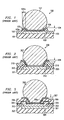
- FIG. 1 illustrates schematically an example of the metallurgical requirements in known technology for a contact pad of a small portion of an IC chip generally designated 100.
- a semiconductor material 101 typically silicon, has patterned aluminum metallization 102 and is protected by a dielectric, moisture-impermeable protective overcoat 103, usually silicon nitride or oxynitride.
- a window has been opened in the overcoat 103 to expose metallization 102 and leave a protective perimeter 103a around metallization 102.
- An additional "under bump" metallization 104 has been deposited unto metallization 102 and patterned so that it overlaps by a distance 104a over the overcoat 103. This additional metallization 104 usually consists of a sequence of thin layers.
- the bottom layer is typically a refractory metal 105, such as chromium, titanium, or tungsten, which provides an ohmic contact to aluminum 102 and a moisture-impenetrable interface to overcoat 103.
- the top metal 106 has to be solderable; examples are gold, copper, nickel, or palladium.
- solder material is deposited, commonly by evaporation, plating or screen-printing, and reflown to form bump 107. These solder bumps assume various shapes (examples are semi-spheres, domes and truncated balls) after the reflow process, influenced by the forces of surface tension during the reflow process.
- One method aims at absorbing part of the thermomechanical stress on the solder joints by plastic material surrounding the joints and filling the gap between chip and substrate. See for instance, U. S. Patents # 6,228,680, issued on May 8, 2001; # 6,213,347, issued on Apr. 10, 2001, and # 6,245,583, issued on Jun. 12, 2001 (Thomas et al., Low Stress Method and Apparatus for Underfilling Flip-Chip Electronic Devices).
- the underfilling method represents an unwelcome process step after device attachment to the motherboard.
- Another method applies a polymer layer on top of the protective overcoat with the aim of reducing the stress to the overcoat perimeter and the dielectric material underlying the contact pad. See for instance the publication "A Silicon and Aluminum Dynamic Memory Technology” by Richard A. Larsen (IBM J. Res. Develop., vol.24, May 1980, pp. 268-282).
- the article includes description of a flip-chip packaging technology using a solder bump on an under-bump metallization, which is resting its perimeter on a thick polyimide layer. The bump structure is often supported by another polyimide layer.
- FIG. 2 illustrates schematically an example of a contact pad, generally designated 200, including a polymer overcoat.
- a silicon chip 201 has patterned aluminum metallization 202 and is protected by a moisture-impermeable inorganic overcoat 203 (silicon nitride) and a polymeric layer 210 (benzocyclobutene or polyimide).
- a window has been opened through both overcoats.
- Layers of under-bump metallization 204 establishes contact to the aluminum, adhesion to both overcoats, and solderablilty to the solder bump 207.
- a structure and a fabrication method are described for metallurgical connections between solder bumps and contact pads positioned on integrated circuits (IC) having copper interconnecting metallization protected by an overcoat.
- the structure comprises a portion of the copper metallization exposed by a window in the overcoat, where the exposed copper has a chemically and plasma cleaned surface.
- a copper layer is directly positioned on the clean copper metallization, and patterned; the resulting metal structure has an electrical (and thermal) conductivity about equal to the conductivity of pure copper.
- the copper layer overlaps the perimeter of the overcoat window and a copper stud is positioned on said copper layer. Finally, one of the solder bumps is bonded to the copper stud.
- the present invention is related to high density and high speed ICs with copper interconnecting metallization, especially those having high numbers of metallized inputs/outputs for flip-chip assembly.
- These circuits can be found in many device families such as processors, digital and analog devices, logic devices, high frequency and high power devices, and in both large and small area chip categories.
- the present invention helps to alleviate the space constraint of continually shrinking applications such as cellular communication, pagers, hard disk drives, laptop computers and other portable electronic devices.
- Another aspect of the invention is to fabricate the contact pad copper cap-layer directly on the IC copper metallization without any intermediate barrier layer, so that the resulting minimum electrical resistance enhances the high speed performance of the IC.
- Another aspect of the invention is the flexibility to select the copper stud deposition method from the following options:
- Another aspect of the invention is to advance the process and reliability of wafer-level functional probing by eliminating probe marks and subsequent plating difficulties.
- Another object of the invention is to provide design and process concepts which are flexible so that they can be applied to many families of semiconductor products, and are general so that they can be applied to several generations of products.
- Another object of the invention is to use only designs and processes most commonly employed and accepted in the fabrication of IC devices, thus avoiding the cost of new capital investment and using the installed fabrication equipment base.
- an oxygen plasma removes organic residues; a subsequent first hydrogen-based plasma removes the controlled copper oxide and passivates the copper surface.
- Sputter etching then creates a fresh copper surface, onto which a copper layer is sputter deposited.
- a second hydrogen plasma passivates the surface. The plating of the copper stud completes the fabrication process.
- the copper layer is sputter-deposited without breaking the vacuum after the first hydrogen plasma.
- the wet clean and second hydrogen plasma can thus be omitted.
- a step of etching in an aqueous inorganic or organic acid is added between the steps of oxygen plasma and hydrogen plasma, in order to remove deep copper pad defects.
- Copper has to be shielded from diffusing into the silicon base material of the ICs in order to protect the circuits from the carrier lifetime killing characteristic of copper atoms positioned in the silicon lattice.
- the formation of thin copper(I)oxide films during the manufacturing process flow has to be prevented or corrected, since these films severely inhibit reliable attachment of solder bumps.
- bare copper bond pads are susceptible to corrosion.
- FIG. 3 illustrates an example emulating the example in FIG. 2.
- the top copper layer 301 of the IC is located over insulating material 302 and protected by inorganic overcoat 303 (usually silicon nitride).
- inorganic overcoat 303 usually silicon nitride.
- a first window is opened in overcoat 303 to expose a portion of copper metal 301.
- An aluminum cap 304 is deposited over the exposed copper 301, slightly overlapping the first window perimeter of overcoat 303.
- An additional pad nitride layer 305 and a polymeric overcoat 306 protect the aluminum 304.
- a second window is opened in pad nitride 305 and polymeric overcoat 306, forming a slope 306a and exposing portion of the aluminum layer 304.
- One, two or more barrier layers 307 are deposited over the exposed aluminum, similar to FIG. 2. The top barrier metal is solderable and contacted by solder bump 308.
- the described approach has several shortcomings.
- Third, the aluminum used for the cap is soft and thus gets severely damaged by the markings of the multiprobe contacts in electrical testing. This damage, in turn, becomes so dominant in the ever decreasing size of the contact pads that the subsequent barrier deposition becomes problematic.
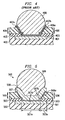
- FIG. 4 Another approach in known technology to overcome the solder attachment problems for copper metallization is depicted in FIG. 4.
- the top copper layer 401 of the IC is located over insulating material 402 and protected by inorganic overcoat 403 (usually silicon nitride) and polymeric overcoat 406.
- a window is opened in both overcoats 403 and 406, forming a slope 406a and exposing a portion of copper metal 401.
- a first barrier layer 407a selected from titanium, tantalum, tungsten, and alloys thereof, is deposited over the exposed copper 401 with the intent to establish good ohmic contact to the copper by "gettering" the oxide away from the copper.
- a second barrier layer 407b commonly nickel vanadium, is deposited to prevent outdiffusion of copper.
- solder bump 408 proceeds directly to screen printing the solder bump 408.
- Another process first sputters a copper seed layer and then electroplates a copper stud; finally, the solder bump is electroplated.
- the result is a contact pad with a high electrical resistance as determined by the resistance of the barrier metal layers. This high electrical pad resistance is counterproductive to the effort aiming at high speed ICs.
- the schematic cross section of FIG. 5 illustrates a metal structure for a contact pad, generally designated 500, of an IC having copper interconnecting metallization.
- the top copper layer 501 of the IC is located over insulating material 502 and protected by inorganic overcoat 503 and polymeric overcoat 506.
- the inorganic overcoat 503 consists preferably of moisture-impermeable silicon nitride, silicon oxynitride, silicon carbide, or multi-layers thereof, preferably in the thickness range from 0.5 to 2.5 ⁇ m.
- the organic overcoat 506 consists preferably of polyimide, benzocyclobutene or related materials, preferably in the thickness range from 3.0 to 10.0 ⁇ m.
- Overcoat 503 overlaps the copper 501 by a length 503a.
- the prime function of this organic material is to help absorb thermomechanical stress transferred by the solder bumps after completion of the device assembly on outside parts such as wiring boards.
- Overcoat 503 and especially the thicker overcoat 506 exhibit a slope 506a towards copper layer 501, brought about by the etching of the overcoats during the window opening process for exposing copper 501.
- the surface 501b of the exposed copper is carefully cleaned; see the process detail below. It is of pivotal importance to the present invention that the cleaned copper surface 501b is free of copper oxide, organic residues, or any contamination so that the interface of copper 501 to the copper layer 507 contributes no measurable electrical resistance to the resistance of contact pad 500.
- the copper layer 507 (deposition techniques see below) is patterned to overlay copper surface 501b and overcoat slope 506a; the preferred thickness range of copper layer 507 is from about 0.3 to 0.8 ⁇ m. Without any contamination of copper layer 507, copper stud 508 is deposited (various deposition methods see below).
- the stud has a thickness from about 10 to 20 ⁇ m; its width is equal to the extent of copper layer 507, following the contour of the overcoat slope 506a. There is no longer a need for any barrier layer as in the prior art depicted in FIGs. 1 to 4.
- the structure consisting of copper stud 508, copper layer 507, and copper metallization 501 exhibits the electrical (and thermal) conductivity of pure copper and thus the lowest possible electrical resistance for contact pad 500.
- solder bump 509 The metallurgical contact pad structure for a flip - chip IC is completed by depositing a solder bump 509; deposition methods see below.
- Preferred solder materials include tin, indium, tin/indium, tin/silver, tin/bismuth, conductive adhesives, and z-axis conductive materials. For some applications, the conventional tin/lead alloy may still be acceptable.
- electroplating is chosen as the method of depositing the copper stud 508
- electroplating is the preferred method of depositing solder bumps 509. This method allows small-pitch solder bumps.
- electroless plating is chosen as the method of depositing the copper stud, screen printing is preferred for the solder bumps; alternatively, pre-fabricated solder balls may be selected. These options require somewhat larger bump pitch.
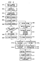
- FIG. 6 shows a block diagram of the preferred wafer-level process flow for direct bumping on copper pads according to the invention.
- the copper layer is sputter-deposited without breaking the vacuum after the first hydrogen plasma.
- the second wet clean and second hydrogen plasma can thus be omitted.
- a step of etching in an aqueous inorganic or organic acid is added between the steps of oxygen plasma and hydrogen plasma, in order to remove deep copper pad defects.
- the invention can be applied to IC bond pad metallizations other than copper, which are difficult or impossible to contact by conventional tin or solder techniques, such as alloys of refractory metals and noble metals.
- the invention can be extended to batch processing, further reducing fabrication costs.
- the invention can be used in hybrid technologies of wire/ribbon bonding and solder interconnections. It is therefore intended that the appended claims encompass any such modifications or embodiments.
Landscapes
- Wire Bonding (AREA)
- Internal Circuitry In Semiconductor Integrated Circuit Devices (AREA)
Abstract
Description
- The present invention is related in general to the field of semiconductor devices and processes and more specifically to the structure and fabrication method of metal bumps for flip-chip assembly of semiconductor chips.
- The structure of contact pad metallizations and solder bumps for connecting integrated circuit (IC) chips to semiconductor packages or outside parts, as well as the thermomechanical stresses and reliability risks involved, have been described in a series of detailed publications by the International Business Machines Corporation in 1969 (IBM J. Res. Develop., Vol. 13, pp. 226 - 296): P. A. Totta et al., SLT Device Metallurgy and its Monolithic Extension, L. F. Miller, Controlled Collapse Reflow Chip Joining, L.S. Goldmann, Geometric Optimization of Controlled Collapse Interconnections, K. C. Norris et al., Reliability of Controlled Collapse Interconnections, S. Oktay, Parametric Study of Temperature Profiles in Chips Joined by Controlled Collapse Techniques, B. S. Berry et al., Studies of the SLT Chip Terminal Metallurgy.
- Based on these publications, FIG. 1 illustrates schematically an example of the metallurgical requirements in known technology for a contact pad of a small portion of an IC chip generally designated 100. A
semiconductor material 101, typically silicon, has patternedaluminum metallization 102 and is protected by a dielectric, moisture-impermeableprotective overcoat 103, usually silicon nitride or oxynitride. A window has been opened in theovercoat 103 to exposemetallization 102 and leave aprotective perimeter 103a aroundmetallization 102. An additional "under bump"metallization 104 has been deposited untometallization 102 and patterned so that it overlaps by adistance 104a over theovercoat 103. Thisadditional metallization 104 usually consists of a sequence of thin layers. The bottom layer is typically arefractory metal 105, such as chromium, titanium, or tungsten, which provides an ohmic contact toaluminum 102 and a moisture-impenetrable interface to overcoat 103. Thetop metal 106 has to be solderable; examples are gold, copper, nickel, or palladium. Finally, solder material is deposited, commonly by evaporation, plating or screen-printing, and reflown to formbump 107. These solder bumps assume various shapes (examples are semi-spheres, domes and truncated balls) after the reflow process, influenced by the forces of surface tension during the reflow process. - During and after assembly of the IC chip to an outside part such as a substrate or circuit board by solder reflow, and then during device operation, significant temperature differences and temperature cycles appear between
semiconductor chip 100 and the substrate. The reliability of the solder joint is strongly influenced by the coefficients of thermal expansion of the semiconductor material and the substrate material. For example, there is more than one order of magnitude difference between the coefficients of thermal expansion of silicon and FR-4. This difference causes thermomechanical stresses, which the solder joints have to absorb. Detailed calculations, in the literature cited above and in other publications of the early 1980's, involving the optimum height and volume of the solder connection and the expected onset of fatigue and cracking proposed a number of solder design solutions. - One method aims at absorbing part of the thermomechanical stress on the solder joints by plastic material surrounding the joints and filling the gap between chip and substrate. See for instance, U. S. Patents # 6,228,680, issued on May 8, 2001; # 6,213,347, issued on Apr. 10, 2001, and # 6,245,583, issued on Jun. 12, 2001 (Thomas et al., Low Stress Method and Apparatus for Underfilling Flip-Chip Electronic Devices). However, the underfilling method represents an unwelcome process step after device attachment to the motherboard.
- Another method applies a polymer layer on top of the protective overcoat with the aim of reducing the stress to the overcoat perimeter and the dielectric material underlying the contact pad. See for instance the publication "A Silicon and Aluminum Dynamic Memory Technology" by Richard A. Larsen (IBM J. Res. Develop., vol.24, May 1980, pp. 268-282). The article includes description of a flip-chip packaging technology using a solder bump on an under-bump metallization, which is resting its perimeter on a thick polyimide layer. The bump structure is often supported by another polyimide layer.
- FIG. 2 illustrates schematically an example of a contact pad, generally designated 200, including a polymer overcoat. A
silicon chip 201 has patternedaluminum metallization 202 and is protected by a moisture-impermeable inorganic overcoat 203 (silicon nitride) and a polymeric layer 210 (benzocyclobutene or polyimide). A window has been opened through both overcoats. Layers of under-bump metallization 204 establishes contact to the aluminum, adhesion to both overcoats, and solderablilty to thesolder bump 207. - An example of a patent based on this approach of a solder ball flip-chip structure designed for stress absorption after mounting is described in the Japanese Patent # 1-209746, issued on 23 Aug. 1989 (Moriyama Yoshifumi, "Semiconductor Device"). The perimeter of the under-bump metallization of the solder ball is supported by a polyimide layer as a heat tolerant resin.
- In high-speed, low electromigration IC's, aluminum has been replaced by copper as chip metallization. Due to bondability and contact resistance issues of copper oxide, it is problematic to establish reliable contact to solder material. Approaches based on adding an interface layer of aluminum, or of metals with higher affinity to oxygen than copper, are costly and not very effective. An urgent need has therefore arisen for a coherent, low-cost method of fabricating flip-chip assembly of semiconductor devices offering a fundamental solution of solder contact to copper and of thermomechanical stress reliability. The method should be flexible enough to be applied for different semiconductor product families and a wide spectrum of design and process variations. Preferably, these innovations should be accomplished using the installed equipment base so that no investment in new manufacturing machines is needed.
- A structure and a fabrication method are described for metallurgical connections between solder bumps and contact pads positioned on integrated circuits (IC) having copper interconnecting metallization protected by an overcoat. The structure comprises a portion of the copper metallization exposed by a window in the overcoat, where the exposed copper has a chemically and plasma cleaned surface. A copper layer is directly positioned on the clean copper metallization, and patterned; the resulting metal structure has an electrical (and thermal) conductivity about equal to the conductivity of pure copper. The copper layer overlaps the perimeter of the overcoat window and a copper stud is positioned on said copper layer. Finally, one of the solder bumps is bonded to the copper stud.
- The present invention is related to high density and high speed ICs with copper interconnecting metallization, especially those having high numbers of metallized inputs/outputs for flip-chip assembly. These circuits can be found in many device families such as processors, digital and analog devices, logic devices, high frequency and high power devices, and in both large and small area chip categories.
- It is an aspect of the present invention to be applicable to contact pad area reduction and thus supports the shrinking of IC chips. Consequently, the invention helps to alleviate the space constraint of continually shrinking applications such as cellular communication, pagers, hard disk drives, laptop computers and other portable electronic devices.
- Another aspect of the invention is to fabricate the contact pad copper cap-layer directly on the IC copper metallization without any intermediate barrier layer, so that the resulting minimum electrical resistance enhances the high speed performance of the IC.
- Another aspect of the invention is the flexibility to select the copper stud deposition method from the following options:
- electroplating the copper stud onto the copper layer, thereby enabling an electroplating process for depositing the solder bump, providing small pitch center-to-center bumps; or
- electroless plating the copper stud onto the copper layer, thereby enabling a screen-printing process for depositing the solder bump, or an attachment process of pre-fabricated solder balls, providing larger pitch center-to-center balls.
- Another aspect of the invention is to advance the process and reliability of wafer-level functional probing by eliminating probe marks and subsequent plating difficulties.
- Another object of the invention is to provide design and process concepts which are flexible so that they can be applied to many families of semiconductor products, and are general so that they can be applied to several generations of products.
- Another object of the invention is to use only designs and processes most commonly employed and accepted in the fabrication of IC devices, thus avoiding the cost of new capital investment and using the installed fabrication equipment base.
- These objects are addressed by the teachings of the invention concerning selection criteria and process flows suitable for mass production. Various modifications have been successfully employed to satisfy different selections of deposition and plating technologies.
- In the first embodiment of the invention, after a wafer cleaning in organic solvents, an oxygen plasma removes organic residues; a subsequent first hydrogen-based plasma removes the controlled copper oxide and passivates the copper surface. Sputter etching then creates a fresh copper surface, onto which a copper layer is sputter deposited. A second hydrogen plasma passivates the surface. The plating of the copper stud completes the fabrication process.
- In the second embodiment of the invention, the copper layer is sputter-deposited without breaking the vacuum after the first hydrogen plasma. The wet clean and second hydrogen plasma can thus be omitted.
- In the third embodiment of the invention, a step of etching in an aqueous inorganic or organic acid is added between the steps of oxygen plasma and hydrogen plasma, in order to remove deep copper pad defects.
- The technical advances represented by the invention, as well as the aspects thereof, will become apparent from the following description of the preferred embodiments of the invention, when considered in conjunction with the accompanying drawings and the novel features set forth in the appended claims.
-
- FIG. 1 is a schematic and simplified cross section of a flip-chip assembly with solder bumps, as fabricated by known technology.
- FIG. 2 is a schematic cross section of a solder bump a nd undermetal arrangement over the chip contact pad metallization according to known technology.
- FIG. 3 is a schematic and simplified cross section of a solder bump and undermetal arrangement over the chip contact pad metallization with an auxiliary aluminum layer according to known technology.
- FIG. 4 is a schematic and simplified cross section of a solder bump and undermetal arrangement over the chip contact pad metallization according to known technology.
- FIG. 5 is a schematic and simplified cross section of a solder bump with copper seed layer and copper stud over the chip contact pad metallization according to the invention.
- FIG. 6 is a block diagram of the process flow for direct bumping on copper pads according to the invention.
-
- The impact of the present invention can be most easily appreciated by highlighting the shortcomings of the known approaches to form contacts to copper-metallized integrated circuits (IC). In the continuing trend to miniaturize the ICs, the RC time constant of the interconnection between active circuit elements increasingly dominates the achievable IC speed-power product. Consequently, the relatively high resistivity of the interconnecting aluminum now appears inferior to the lower resistivity of metals such as copper. Further, the pronounced sensitivity of aluminum to electromigration is becoming a serious obstacle. Consequently, there is now a strong drive in the semiconductor industry to employ copper as the preferred interconnecting metal, based on its higher electrical conductivity and lower electromigration sensitivity.
- Copper has to be shielded from diffusing into the silicon base material of the ICs in order to protect the circuits from the carrier lifetime killing characteristic of copper atoms positioned in the silicon lattice. For bond pads made of copper, the formation of thin copper(I)oxide films during the manufacturing process flow has to be prevented or corrected, since these films severely inhibit reliable attachment of solder bumps. As a further difficulty, bare copper bond pads are susceptible to corrosion.
- In order to overcome these problems, structures and processes have been disclosed to cap the clean copper bond pad with a layer of aluminum and thus re-construct the traditional situation of an aluminum pad. For conventional gold wire bonding, a suitable bonding process is described in U.S. Patent # 5,785,236, issued on Jul. 28, 1998 (Cheung et al., "Advanced Copper Interconnect System that is Compatible with Existing IC Wire Bonding Technology"). For solder bumps structures, FIG. 3 illustrates an example emulating the example in FIG. 2. The
top copper layer 301 of the IC is located over insulatingmaterial 302 and protected by inorganic overcoat 303 (usually silicon nitride). A first window is opened inovercoat 303 to expose a portion ofcopper metal 301. Analuminum cap 304 is deposited over the exposedcopper 301, slightly overlapping the first window perimeter ofovercoat 303. An additionalpad nitride layer 305 and apolymeric overcoat 306 protect thealuminum 304. A second window is opened inpad nitride 305 andpolymeric overcoat 306, forming aslope 306a and exposing portion of thealuminum layer 304. One, two or more barrier layers 307 are deposited over the exposed aluminum, similar to FIG. 2. The top barrier metal is solderable and contacted bysolder bump 308. - The described approach, however, has several shortcomings. First, the additional fabrication cost of the aluminum cap is not desired, since the process requires additional steps for depositing metal, patterning, etching, and cleaning. Second, the aluminum must have a barrier cap with good contact to the aluminum and solderability to the solder bump. Third, the aluminum used for the cap is soft and thus gets severely damaged by the markings of the multiprobe contacts in electrical testing. This damage, in turn, becomes so dominant in the ever decreasing size of the contact pads that the subsequent barrier deposition becomes problematic.
- Another approach in known technology to overcome the solder attachment problems for copper metallization is depicted in FIG. 4. The
top copper layer 401 of the IC is located over insulatingmaterial 402 and protected by inorganic overcoat 403 (usually silicon nitride) andpolymeric overcoat 406. A window is opened in bothovercoats slope 406a and exposing a portion ofcopper metal 401. Afirst barrier layer 407a, selected from titanium, tantalum, tungsten, and alloys thereof, is deposited over the exposedcopper 401 with the intent to establish good ohmic contact to the copper by "gettering" the oxide away from the copper. Asecond barrier layer 407b, commonly nickel vanadium, is deposited to prevent outdiffusion of copper. From here, one process proceeds directly to screen printing thesolder bump 408. Another process first sputters a copper seed layer and then electroplates a copper stud; finally, the solder bump is electroplated. In either case, the result is a contact pad with a high electrical resistance as determined by the resistance of the barrier metal layers. This high electrical pad resistance is counterproductive to the effort aiming at high speed ICs. - These shortcomings and difficulties are resolved by the process and the structure of the invention. The schematic cross section of FIG. 5 illustrates a metal structure for a contact pad, generally designated 500, of an IC having copper interconnecting metallization. The
top copper layer 501 of the IC is located over insulatingmaterial 502 and protected byinorganic overcoat 503 andpolymeric overcoat 506. Theinorganic overcoat 503 consists preferably of moisture-impermeable silicon nitride, silicon oxynitride, silicon carbide, or multi-layers thereof, preferably in the thickness range from 0.5 to 2.5 µm. Theorganic overcoat 506 consists preferably of polyimide, benzocyclobutene or related materials, preferably in the thickness range from 3.0 to 10.0 µm.Overcoat 503 overlaps thecopper 501 by a length 503a. The prime function of this organic material is to help absorb thermomechanical stress transferred by the solder bumps after completion of the device assembly on outside parts such as wiring boards.Overcoat 503 and especially thethicker overcoat 506 exhibit aslope 506a towardscopper layer 501, brought about by the etching of the overcoats during the window opening process for exposingcopper 501. - After opening the
window 501a, thesurface 501b of the exposed copper is carefully cleaned; see the process detail below. It is of pivotal importance to the present invention that the cleanedcopper surface 501b is free of copper oxide, organic residues, or any contamination so that the interface ofcopper 501 to thecopper layer 507 contributes no measurable electrical resistance to the resistance ofcontact pad 500. - The copper layer 507 (deposition techniques see below) is patterned to
overlay copper surface 501b andovercoat slope 506a; the preferred thickness range ofcopper layer 507 is from about 0.3 to 0.8 µm. Without any contamination ofcopper layer 507,copper stud 508 is deposited (various deposition methods see below). The stud has a thickness from about 10 to 20 µm; its width is equal to the extent ofcopper layer 507, following the contour of theovercoat slope 506a. There is no longer a need for any barrier layer as in the prior art depicted in FIGs. 1 to 4. - With no contribution to the electrical resistance at
interfaces copper stud 508,copper layer 507, andcopper metallization 501 exhibits the electrical (and thermal) conductivity of pure copper and thus the lowest possible electrical resistance forcontact pad 500. - The metallurgical contact pad structure for a flip - chip IC is completed by depositing a
solder bump 509; deposition methods see below. Preferred solder materials include tin, indium, tin/indium, tin/silver, tin/bismuth, conductive adhesives, and z-axis conductive materials. For some applications, the conventional tin/lead alloy may still be acceptable. When electroplating is chosen as the method of depositing thecopper stud 508, electroplating is the preferred method of depositing solder bumps 509. This method allows small-pitch solder bumps. When electroless plating is chosen as the method of depositing the copper stud, screen printing is preferred for the solder bumps; alternatively, pre-fabricated solder balls may be selected. These options require somewhat larger bump pitch. - FIG. 6 shows a block diagram of the preferred wafer-level process flow for direct bumping on copper pads according to the invention; first embodiment.
- Step 601: Input: IC wafer from the wafer Fab. The wafer has copper interconnecting metallization.
- Step 602: Etching the contact window: Etching the
polymeric overcoat (for instance, benzocylobutene
or polyimide) using a hot wet etch in basic
developer (tetramethyl ammonium hydroxide) in order
to open the window for the contact pad. The wet
etch results in a relatively gentle slope of the
overcoat around the window perimeter towards the
copper of the pad.
Etching the inorganic overcoat (for instance, silicon nitride or silicon oxynitride) using a fluoride-containing plasma in order to expose the copper pad of the IC metallization. At this stage, the pad still has an (uncontrolled) copper oxide surface; it may further be contaminated with organic residues (such as photoresist) and/or particulates. - Step 603: Exposing the wafer to organic solvents, thereby
removing organic contamination and mechanical
particles from the copper contact pads. Examples
of suitable cleaning processes include:
- submerging the wafer in agitated isopropyl alcohol, methanol, glycol, N-methyl pyrrolidone and other solvents;
- adding ultrasonic/megasonic energy to these solvents;
- spraying the wafer with an organic solvent;
- treating the wafer in dry chemical vapor.
- Step 604: Drying the wafer in dry nitrogen.
- Step 605: Exposing the wafer to an oxygen and nitrogen/ helium/argon plasma, thereby ashing any further organic residues on the copper contact pads and oxidizing the copper surface to a controlled thickness of less than 10 nm. Preferred plasma pressure between 0.1 and 10 Torr at 0.2 to 1.0 mol fraction oxygen and 0 to 0.8 mol fraction helium/argon; flow rate between 2.0 and 4.0 slpm. Temperature range is between 25 and 250 °C, time from 0.5 to 5 min.
- Step 606: Without breaking the vacuum, exposing the wafer to a first hydrogen and nitrogen/helium/argon plasma, thereby removing the controlled copper oxide from the pad surface and passivating the cleaned surface. Preferred plasma pressure between 0.1 to 10 Torr at 0.2 to 1.0 mol fraction hydrogen, 0 to 0.8 mol fraction nitrogen, and 0 to 0.8 mol fraction helium/argon; flow rate between 2.0 and 4.0 slpm. Temperature range is between 25 and 25 °C, time from 0.5 to 5.0 min.
- Step 607: Deciding whether to transfer the wafer directly to further processing under vacuum, or, alternately submit it to wet cleaning.
- Step 608: Wet cleaning the wafer in order to remove the oxidized ("ashed") materials. Wet cleaning agents include, for example, dilute citric, acetic, or oxalic acids. Temperature range is between 25 and 80 °C, time from 0.5 to 15 min.
- Step 609: Exposing the wafer to a hydrogen and nitrogen/argon plasma, thereby cleaning and passivating the copper layer in the photoresist window.
- Step 610: Sputter-etching the passivated pad surface with energetic ions, thereby creating a fresh surface and concurrently activating it. Preferred plasma pressure between 5 and 100 mTorr at 750 to 1000 V bias. Temperature range is between 25 and 400 °C, time from 1.0 to 4.0 min.
- Step 611: Sputter-depositing a layer of copper covering the fresh pad surface and pad perimeter, this layer providing minimal electrical resistance and thermo-mechanical stress to the pad. This copper layer may also be referred to as "seed layer".
- Step 612: Creating a window in photoresist cover:
- coating the wafer with photoresist;
- exposing the window and masking the remainder;
- developing the photoresist; and
- ultra-violet (UV) curing the photoresist.
- Step 613: Exposing the wafer to a hydrogen and nitrogen/argon plasma, thereby cleaning and passivating the copper layer in the photoresist window.
-
Step 614a and 614b: Without exposing the passivated copper layer to fresh contamination, depositing a copper stud onto the exposed copper layer. There are two options for this deposition step: - Step 614a: Electroplating the copper stud; or
-
Step 614b: Electroless plating the copper stud. -
Step 615a and 615b: Depositing a tin/solder bump onto the copper stud. There are two options for this deposition step:- Step 615a: Electroplating the tin/solder bump. This is the preferred option, when the copper stud was electroplated.
-
Step 615b: Screen-printing the tin/solder bump; or attaching a prefabricated tin/solder ball.
Any one of these two methods is the preferred option, when the copper stud was electroless plated.
- Step 616: Stripping the photoresist.
- Step 617: Etching the copper (seed) layer.
- Step 618: Output: IC wafer with copper and tin/solder directly bumped on copper pads for optimum electrical conductivity.
- In the second embodiment of the process flow, the copper layer is sputter-deposited without breaking the vacuum after the first hydrogen plasma. The second wet clean and second hydrogen plasma can thus be omitted.
- In the third embodiment of the process flow, a step of etching in an aqueous inorganic or organic acid is added between the steps of oxygen plasma and hydrogen plasma, in order to remove deep copper pad defects.
- While this invention has been described in reference to illustrative embodiments, this description is not intended to be construed in a limiting sense. Various modifications and combinations of the illustrative embodiments, as well as other embodiments of the invention,
will be apparent to persons skilled in the art upon reference to the description. As an example, the invention can be applied to IC bond pad metallizations other than copper, which are difficult or impossible to contact by conventional tin or solder techniques, such as alloys of refractory metals and noble metals. As another example, the invention can be extended to batch processing, further reducing fabrication costs. As another example, the invention can be used in hybrid technologies of wire/ribbon bonding and solder interconnections. It is therefore intended that the appended claims encompass any such modifications or embodiments.
Claims (10)
- A metal structure for a contact pad of an integrated circuit having copper interconnecting metallization protected by an overcoat, comprising:a portion of said copper metallization exposed by a window in said overcoat;said exposed copper having a clean surface;a patterned copper layer directly positioned on said clean copper metallization, whereby said metal structure has an electrical conductivity about equal to the conductivity of pure copper, said layer overlapping the perimeter of said overcoat window; anda copper stud positioned on said copper layer, following the contours of said copper layer.
- The metal structure according to Claim 1 wherein said overcoat is a moisture-impermeable inorganic layer including silicon nitride and silicon oxynitride.
- The metal structure according to Claim 1 wherein said overcoat is a sequence of an inorganic layer adjacent to the integrated circuit, overlaid by a polymeric layer including polyimide, benzocylobutene, and
polybenzoxazole capable of absorbing thermomechanical stress. - The metal structure according to any one of Claims 1, 2 or 3 wherein said copper stud has a width equal to the extent of said copper layer, following the contour of said perimeter of said overcoat window.
- A wafer-level method for cleaning the surface of copper metallization used as integrated circuit interconnection and exposed in contact pads, comprising the steps of:exposing said wafer to organic solvents, thereby removing organic contamination and mechanical particles from said copper contact pads, and drying said wafer;exposing said wafer to an oxygen and nitrogen/argon/helium plasma, thereby ashing any organic residue on said copper contact pads and oxidizing said copper surface to a controlled thickness;without breaking the vacuum, exposing said wafer to a first hydrogen and nitrogen/helium/argon plasma, thereby removing said controlled copper oxide from said pad surface and passivating said cleaned surface;sputter-etching said passivated pad surface with energetic ions, thereby creating a fresh surface and concurrently activating it;sputter-depositing a layer of copper covering said fresh pad surface and pad perimeter;exposing said wafer to a second hydrogen and nitrogen/argon plasma, thereby passivating said copper layer; andwithout exposing said passivated copper layer to fresh contamination, depositing a copper stud onto said copper layer.
- The method according to Claim 5 further comprising the process step of depositing a solder bump onto said copper stud.
- The method according to Claim 5 or 6 wherein said process step of depositing a copper stud is selected from a group of processes consisting of:electroplating said copper stud onto said copper layer, thereby enabling an electroplating process for depositing said solder bump, providing small pitch center-to-center bumps; andelectroless plating said copper stud onto said copper layer, thereby enabling a screen-printing process for depositing said solder bump, or an attachment process of pre-fabricated solder balls, providing large pitch center-to-center balls.
- The method according to Claim 5, 6 or 7 wherein said process step of exposing the wafer to solvents is selected from a group of processes consisting of:submerging said wafer in agitated isopropyl alcohol, methanol, glycol, N-methyl pyrrolidone and other solvents;adding ultrasonic energy to said solvent;spraying said wafer with an organic solvent; andtreating said wafer in dry chemical vapor.
- The method according to any one of Claims 5 to 8 further comprising, between said steps of oxygen plasma and hydrogen plasma, the step of etching in an aqueous inorganic or organic acid, thereby removing deep copper pad defects.
- The method according to any one of Claims 5 to 9 wherein said step of sputter-depositing a layer of copper is performed without breaking the vacuum after said step of first hydrogen plasma cleaning, thereby omitting the second wet and hydrogen-based cleanings.
Applications Claiming Priority (4)
| Application Number | Priority Date | Filing Date | Title |
|---|---|---|---|
| US86117 | 1987-08-17 | ||
| US34294901P | 2001-12-21 | 2001-12-21 | |
| US342949 | 2001-12-21 | ||
| US10/086,117 US20030116845A1 (en) | 2001-12-21 | 2002-02-26 | Waferlevel method for direct bumping on copper pads in integrated circuits |
Publications (3)
| Publication Number | Publication Date |
|---|---|
| EP1321982A2 true EP1321982A2 (en) | 2003-06-25 |
| EP1321982A3 EP1321982A3 (en) | 2009-07-29 |
| EP1321982B1 EP1321982B1 (en) | 2011-07-27 |
Family
ID=26774381
Family Applications (1)
| Application Number | Title | Priority Date | Filing Date |
|---|---|---|---|
| EP02102839A Expired - Lifetime EP1321982B1 (en) | 2001-12-21 | 2002-12-19 | Wafer-level method of fabricating a contact pad copper cap layer |
Country Status (2)
| Country | Link |
|---|---|
| US (2) | US20030116845A1 (en) |
| EP (1) | EP1321982B1 (en) |
Cited By (4)
| Publication number | Priority date | Publication date | Assignee | Title |
|---|---|---|---|---|
| DE102005035771A1 (en) * | 2005-07-29 | 2007-02-01 | Advanced Micro Devices, Inc., Sunnyvale | Semiconductor component for integrated circuits, has bump bottom-face metallization layer formed on copper-containing contact surface |
| DE102008020924A1 (en) * | 2008-04-25 | 2009-11-05 | Siemens Aktiengesellschaft | Electrical and/or mechanical connections manufacturing method for gamma or X-ray detectors, involves producing elevation as seed layer, metallic column and solder layer based on substrate or electronic element |
| CN103794513A (en) * | 2012-10-26 | 2014-05-14 | 中国科学院上海微系统与信息技术研究所 | Method for enhancing adhesion between dielectric layer PI and metal Cu layer |
| CN105633043A (en) * | 2014-11-03 | 2016-06-01 | 中芯国际集成电路制造(上海)有限公司 | Semiconductor device, manufacturing method thereof and electronic device |
Families Citing this family (30)
| Publication number | Priority date | Publication date | Assignee | Title |
|---|---|---|---|---|
| JP2003198117A (en) * | 2001-12-28 | 2003-07-11 | Matsushita Electric Ind Co Ltd | Soldering method and joint structure |
| TW513770B (en) * | 2002-02-26 | 2002-12-11 | Advanced Semiconductor Eng | Wafer bumping process |
| US20040036171A1 (en) * | 2002-08-22 | 2004-02-26 | Farnworth Warren M. | Method and apparatus for enabling a stitch wire bond in the absence of discrete bump formation, semiconductor device assemblies and electronic systems including same |
| US6964881B2 (en) * | 2002-08-27 | 2005-11-15 | Micron Technology, Inc. | Multi-chip wafer level system packages and methods of forming same |
| TWI291210B (en) * | 2002-09-10 | 2007-12-11 | Advanced Semiconductor Eng | Under-bump-metallurgy layer |
| US7138293B2 (en) * | 2002-10-04 | 2006-11-21 | Dalsa Semiconductor Inc. | Wafer level packaging technique for microdevices |
| AU2003266560A1 (en) * | 2002-12-09 | 2004-06-30 | Yoshihiro Hayashi | Copper alloy for wiring, semiconductor device, method for forming wiring and method for manufacturing semiconductor device |
| US7095116B1 (en) * | 2003-12-01 | 2006-08-22 | National Semiconductor Corporation | Aluminum-free under bump metallization structure |
| JP4352880B2 (en) * | 2003-12-02 | 2009-10-28 | セイコーエプソン株式会社 | Cleaning method and cleaning device |
| KR100605315B1 (en) | 2004-07-30 | 2006-07-28 | 삼성전자주식회사 | Input / Output Pad Structure of Integrated Circuit Chip |
| TWI251890B (en) * | 2004-11-05 | 2006-03-21 | Advanced Semiconductor Eng | Wafer structure, chip structure and bumping process |
| US7282433B2 (en) * | 2005-01-10 | 2007-10-16 | Micron Technology, Inc. | Interconnect structures with bond-pads and methods of forming bump sites on bond-pads |
| US7323406B2 (en) | 2005-01-27 | 2008-01-29 | Chartered Semiconductor Manufacturing Ltd. | Elevated bond-pad structure for high-density flip-clip packaging and a method of fabricating the structures |
| KR100630737B1 (en) * | 2005-02-04 | 2006-10-02 | 삼성전자주식회사 | Metal CMP Cleaning Solution and Metal Wiring Forming Method Using the Same |
| TWI245345B (en) * | 2005-02-17 | 2005-12-11 | Touch Micro System Tech | Method of forming a wear-resistant dielectric layer |
| CN100437936C (en) * | 2005-02-25 | 2008-11-26 | 探微科技股份有限公司 | Method for manufacturing abrasion-resistant dielectric layer |
| US20070045812A1 (en) * | 2005-08-31 | 2007-03-01 | Micron Technology, Inc. | Microfeature assemblies including interconnect structures and methods for forming such interconnect structures |
| WO2007074351A1 (en) * | 2005-12-29 | 2007-07-05 | Infineon Technologies Ag | Substrate with contact studs of improved quality |
| US8334209B2 (en) | 2006-09-21 | 2012-12-18 | Micron Technology, Inc. | Method of reducing electron beam damage on post W-CMP wafers |
| TWI397978B (en) * | 2007-12-12 | 2013-06-01 | 財團法人工業技術研究院 | Wafer structure and its process and flip chip package structure and process |
| JP5249080B2 (en) * | 2009-02-19 | 2013-07-31 | セイコーインスツル株式会社 | Semiconductor device |
| US11134598B2 (en) * | 2009-07-20 | 2021-09-28 | Set North America, Llc | 3D packaging with low-force thermocompression bonding of oxidizable materials |
| US8659155B2 (en) * | 2009-11-05 | 2014-02-25 | Taiwan Semiconductor Manufacturing Company, Ltd. | Mechanisms for forming copper pillar bumps |
| US8344506B2 (en) * | 2009-12-08 | 2013-01-01 | Taiwan Semiconductor Manufacturing Company, Ltd. | Interface structure for copper-copper peeling integrity |
| TW201208007A (en) * | 2010-08-02 | 2012-02-16 | Advanced Semiconductor Eng | Semiconductor package |
| US8835301B2 (en) | 2011-02-28 | 2014-09-16 | Stats Chippac, Ltd. | Semiconductor device and method of forming bump structure with insulating buffer layer to reduce stress on semiconductor wafer |
| US9269658B2 (en) * | 2013-03-11 | 2016-02-23 | Taiwan Semiconductor Manufacturing Company, Ltd. | Ball amount process in the manufacturing of integrated circuit |
| US9731677B1 (en) * | 2016-04-18 | 2017-08-15 | Ford Global Technologies, Llc | Passive restraint system |
| KR102073295B1 (en) * | 2018-06-22 | 2020-02-04 | 삼성전자주식회사 | Semiconductor package |
| US10957664B2 (en) * | 2019-05-29 | 2021-03-23 | Taiwan Semiconductor Manufacturing Company Ltd. | Semiconductor structure and manufacturing method thereof |
Family Cites Families (21)
| Publication number | Priority date | Publication date | Assignee | Title |
|---|---|---|---|---|
| US4514751A (en) * | 1982-12-23 | 1985-04-30 | International Business Machines Corporation | Compressively stresses titanium metallurgy for contacting passivated semiconductor devices |
| DE68927931T2 (en) * | 1989-07-26 | 1997-09-18 | Ibm | Method of manufacturing a package structure for an integrated circuit chip |
| US5656858A (en) * | 1994-10-19 | 1997-08-12 | Nippondenso Co., Ltd. | Semiconductor device with bump structure |
| US5785236A (en) * | 1995-11-29 | 1998-07-28 | Advanced Micro Devices, Inc. | Advanced copper interconnect system that is compatible with existing IC wire bonding technology |
| TW448524B (en) * | 1997-01-17 | 2001-08-01 | Seiko Epson Corp | Electronic component, semiconductor device, manufacturing method therefor, circuit board and electronic equipment |
| KR100219806B1 (en) * | 1997-05-27 | 1999-09-01 | 윤종용 | Method for manufacturing flip chip mounted solder bumps of semiconductor device, solder bumps manufactured accordingly, and analysis method thereof |
| US6107192A (en) * | 1997-12-30 | 2000-08-22 | Applied Materials, Inc. | Reactive preclean prior to metallization for sub-quarter micron application |
| KR100643105B1 (en) * | 1998-05-06 | 2006-11-13 | 텍사스 인스트루먼츠 인코포레이티드 | Low stress method and apparatus for underfilling flip-chip electronic devices |
| JPH11345837A (en) * | 1998-05-06 | 1999-12-14 | Texas Instr Inc <Ti> | Method and apparatus for reducing distortion of underfilling flip-chip electronic device |
| US6245583B1 (en) * | 1998-05-06 | 2001-06-12 | Texas Instruments Incorporated | Low stress method and apparatus of underfilling flip-chip electronic devices |
| US5943597A (en) * | 1998-06-15 | 1999-08-24 | Motorola, Inc. | Bumped semiconductor device having a trench for stress relief |
| US7053002B2 (en) * | 1998-12-04 | 2006-05-30 | Applied Materials, Inc | Plasma preclean with argon, helium, and hydrogen gases |
| DE19915245A1 (en) * | 1999-04-03 | 2000-10-05 | Philips Corp Intellectual Pty | Electronic component with strip conductor, e.g. coil or coupler for high frequency application and high speed digital circuits, is produced by conductive layer deposition on metal base layer regions exposed by structured photolacquer layer |
| EP1050905B1 (en) * | 1999-05-07 | 2017-06-21 | Shinko Electric Industries Co. Ltd. | Method of producing a semiconductor device with insulating layer |
| US6133136A (en) * | 1999-05-19 | 2000-10-17 | International Business Machines Corporation | Robust interconnect structure |
| US6080656A (en) * | 1999-09-01 | 2000-06-27 | Taiwan Semiconductor Manufacturing Company | Method for forming a self-aligned copper structure with improved planarity |
| KR100345035B1 (en) * | 1999-11-06 | 2002-07-24 | 한국과학기술원 | The Method for Preparation of Flip chip Bump and UBM for High speed Copper Interconnect Chip Using Electroless Plating Method |
| TW449813B (en) * | 2000-10-13 | 2001-08-11 | Advanced Semiconductor Eng | Semiconductor device with bump electrode |
| US6445069B1 (en) * | 2001-01-22 | 2002-09-03 | Flip Chip Technologies, L.L.C. | Electroless Ni/Pd/Au metallization structure for copper interconnect substrate and method therefor |
| US6818545B2 (en) * | 2001-03-05 | 2004-11-16 | Megic Corporation | Low fabrication cost, fine pitch and high reliability solder bump |
| US6667230B2 (en) * | 2001-07-12 | 2003-12-23 | Taiwan Semiconductor Manufacturing Co., Ltd. | Passivation and planarization process for flip chip packages |
-
2002
- 2002-02-26 US US10/086,117 patent/US20030116845A1/en not_active Abandoned
- 2002-12-19 EP EP02102839A patent/EP1321982B1/en not_active Expired - Lifetime
-
2004
- 2004-02-09 US US10/773,864 patent/US20040157450A1/en not_active Abandoned
Non-Patent Citations (1)
| Title |
|---|
| None |
Cited By (7)
| Publication number | Priority date | Publication date | Assignee | Title |
|---|---|---|---|---|
| DE102005035771A1 (en) * | 2005-07-29 | 2007-02-01 | Advanced Micro Devices, Inc., Sunnyvale | Semiconductor component for integrated circuits, has bump bottom-face metallization layer formed on copper-containing contact surface |
| US7569937B2 (en) | 2005-07-29 | 2009-08-04 | Advanced Micro Devices, Inc. | Technique for forming a copper-based contact layer without a terminal metal |
| DE102005035771B4 (en) | 2005-07-29 | 2020-06-18 | Advanced Micro Devices, Inc. | Technique for producing a copper-based contact layer without an end metal |
| DE102008020924A1 (en) * | 2008-04-25 | 2009-11-05 | Siemens Aktiengesellschaft | Electrical and/or mechanical connections manufacturing method for gamma or X-ray detectors, involves producing elevation as seed layer, metallic column and solder layer based on substrate or electronic element |
| CN103794513A (en) * | 2012-10-26 | 2014-05-14 | 中国科学院上海微系统与信息技术研究所 | Method for enhancing adhesion between dielectric layer PI and metal Cu layer |
| CN103794513B (en) * | 2012-10-26 | 2016-12-21 | 中国科学院上海微系统与信息技术研究所 | The method of adhesiveness between amplified medium layer PI and Ni metal layer |
| CN105633043A (en) * | 2014-11-03 | 2016-06-01 | 中芯国际集成电路制造(上海)有限公司 | Semiconductor device, manufacturing method thereof and electronic device |
Also Published As
| Publication number | Publication date |
|---|---|
| US20040157450A1 (en) | 2004-08-12 |
| US20030116845A1 (en) | 2003-06-26 |
| EP1321982A3 (en) | 2009-07-29 |
| EP1321982B1 (en) | 2011-07-27 |
Similar Documents
| Publication | Publication Date | Title |
|---|---|---|
| EP1321982B1 (en) | Wafer-level method of fabricating a contact pad copper cap layer | |
| US20040007779A1 (en) | Wafer-level method for fine-pitch, high aspect ratio chip interconnect | |
| US7005752B2 (en) | Direct bumping on integrated circuit contacts enabled by metal-to-insulator adhesion | |
| CN100550327C (en) | Shared spherical confinement metallurgy for input and output locations and method of forming same | |
| US8481418B2 (en) | Low fabrication cost, high performance, high reliability chip scale package | |
| US6642136B1 (en) | Method of making a low fabrication cost, high performance, high reliability chip scale package | |
| US7262126B2 (en) | Sealing and protecting integrated circuit bonding pads | |
| CN1096110C (en) | Solder bump structure containing titanium barrier layer and method of forming same | |
| JP3172501B2 (en) | Titanium-tungsten alloy etching method and etchant solution | |
| US20080251927A1 (en) | Electromigration-Resistant Flip-Chip Solder Joints | |
| US20040206801A1 (en) | Electronic devices including metallurgy structures for wire and solder bonding | |
| US7550849B2 (en) | Conductive structures including titanium-tungsten base layers | |
| JP2003224158A (en) | Flip chip for substrate assembly without bump and polymer layer | |
| US20030164552A1 (en) | Under-ball metallic layer | |
| JPH11186309A (en) | Semiconductor device and method of manufacturing semiconductor device | |
| WO2005062367A1 (en) | I/o sites for probe test and wire bond |
Legal Events
| Date | Code | Title | Description |
|---|---|---|---|
| PUAI | Public reference made under article 153(3) epc to a published international application that has entered the european phase |
Free format text: ORIGINAL CODE: 0009012 |
|
| AK | Designated contracting states |
Designated state(s): AT BE BG CH CY CZ DE DK EE ES FI FR GB GR IE IT LI LU MC NL PT SE SI SK TR |
|
| AX | Request for extension of the european patent |
Extension state: AL LT LV MK RO |
|
| PUAL | Search report despatched |
Free format text: ORIGINAL CODE: 0009013 |
|
| AK | Designated contracting states |
Kind code of ref document: A3 Designated state(s): AT BE BG CH CY CZ DE DK EE ES FI FR GB GR IE IT LI LU MC NL PT SE SI SK TR |
|
| AX | Request for extension of the european patent |
Extension state: AL LT LV MK RO |
|
| 17P | Request for examination filed |
Effective date: 20100129 |
|
| 17Q | First examination report despatched |
Effective date: 20100304 |
|
| AKX | Designation fees paid |
Designated state(s): DE FR GB |
|
| RBV | Designated contracting states (corrected) |
Designated state(s): DE FR GB NL |
|
| RIC1 | Information provided on ipc code assigned before grant |
Ipc: H01L 21/60 20060101AFI20101125BHEP |
|
| RTI1 | Title (correction) |
Free format text: WAFER-LEVEL METHOD OF FABRICATING A CONTACT PAD COPPER CAP LAYER |
|
| GRAP | Despatch of communication of intention to grant a patent |
Free format text: ORIGINAL CODE: EPIDOSNIGR1 |
|
| GRAJ | Information related to disapproval of communication of intention to grant by the applicant or resumption of examination proceedings by the epo deleted |
Free format text: ORIGINAL CODE: EPIDOSDIGR1 |
|
| GRAP | Despatch of communication of intention to grant a patent |
Free format text: ORIGINAL CODE: EPIDOSNIGR1 |
|
| GRAS | Grant fee paid |
Free format text: ORIGINAL CODE: EPIDOSNIGR3 |
|
| GRAA | (expected) grant |
Free format text: ORIGINAL CODE: 0009210 |
|
| AK | Designated contracting states |
Kind code of ref document: B1 Designated state(s): DE FR GB NL |
|
| REG | Reference to a national code |
Ref country code: GB Ref legal event code: FG4D |
|
| REG | Reference to a national code |
Ref country code: DE Ref legal event code: R096 Ref document number: 60240597 Country of ref document: DE Effective date: 20110915 |
|
| REG | Reference to a national code |
Ref country code: NL Ref legal event code: VDEP Effective date: 20110727 |
|
| PG25 | Lapsed in a contracting state [announced via postgrant information from national office to epo] |
Ref country code: NL Free format text: LAPSE BECAUSE OF FAILURE TO SUBMIT A TRANSLATION OF THE DESCRIPTION OR TO PAY THE FEE WITHIN THE PRESCRIBED TIME-LIMIT Effective date: 20110727 |
|
| PLBE | No opposition filed within time limit |
Free format text: ORIGINAL CODE: 0009261 |
|
| STAA | Information on the status of an ep patent application or granted ep patent |
Free format text: STATUS: NO OPPOSITION FILED WITHIN TIME LIMIT |
|
| 26N | No opposition filed |
Effective date: 20120502 |
|
| REG | Reference to a national code |
Ref country code: DE Ref legal event code: R097 Ref document number: 60240597 Country of ref document: DE Effective date: 20120502 |
|
| REG | Reference to a national code |
Ref country code: FR Ref legal event code: PLFP Year of fee payment: 14 |
|
| REG | Reference to a national code |
Ref country code: FR Ref legal event code: PLFP Year of fee payment: 15 |
|
| REG | Reference to a national code |
Ref country code: FR Ref legal event code: PLFP Year of fee payment: 16 |
|
| PGFP | Annual fee paid to national office [announced via postgrant information from national office to epo] |
Ref country code: DE Payment date: 20181114 Year of fee payment: 17 |
|
| PGFP | Annual fee paid to national office [announced via postgrant information from national office to epo] |
Ref country code: GB Payment date: 20181129 Year of fee payment: 17 Ref country code: FR Payment date: 20181120 Year of fee payment: 17 |
|
| REG | Reference to a national code |
Ref country code: DE Ref legal event code: R119 Ref document number: 60240597 Country of ref document: DE |
|
| GBPC | Gb: european patent ceased through non-payment of renewal fee |
Effective date: 20191219 |
|
| PG25 | Lapsed in a contracting state [announced via postgrant information from national office to epo] |
Ref country code: FR Free format text: LAPSE BECAUSE OF NON-PAYMENT OF DUE FEES Effective date: 20191231 Ref country code: DE Free format text: LAPSE BECAUSE OF NON-PAYMENT OF DUE FEES Effective date: 20200701 Ref country code: GB Free format text: LAPSE BECAUSE OF NON-PAYMENT OF DUE FEES Effective date: 20191219 |