EP1321899A2 - Method and apparatus for enhancing the contrast of a medical diagnostic image acquired using collimation - Google Patents
Method and apparatus for enhancing the contrast of a medical diagnostic image acquired using collimation Download PDFInfo
- Publication number
- EP1321899A2 EP1321899A2 EP02258040A EP02258040A EP1321899A2 EP 1321899 A2 EP1321899 A2 EP 1321899A2 EP 02258040 A EP02258040 A EP 02258040A EP 02258040 A EP02258040 A EP 02258040A EP 1321899 A2 EP1321899 A2 EP 1321899A2
- Authority
- EP
- European Patent Office
- Prior art keywords
- collimator
- data
- subject
- ray
- contrast
- Prior art date
- Legal status (The legal status is an assumption and is not a legal conclusion. Google has not performed a legal analysis and makes no representation as to the accuracy of the status listed.)
- Granted
Links
Images


Classifications
-
- G—PHYSICS
- G06—COMPUTING OR CALCULATING; COUNTING
- G06T—IMAGE DATA PROCESSING OR GENERATION, IN GENERAL
- G06T5/00—Image enhancement or restoration
- G06T5/90—Dynamic range modification of images or parts thereof
- G06T5/94—Dynamic range modification of images or parts thereof based on local image properties, e.g. for local contrast enhancement
-
- A—HUMAN NECESSITIES
- A61—MEDICAL OR VETERINARY SCIENCE; HYGIENE
- A61B—DIAGNOSIS; SURGERY; IDENTIFICATION
- A61B6/00—Apparatus or devices for radiation diagnosis; Apparatus or devices for radiation diagnosis combined with radiation therapy equipment
-
- G—PHYSICS
- G06—COMPUTING OR CALCULATING; COUNTING
- G06T—IMAGE DATA PROCESSING OR GENERATION, IN GENERAL
- G06T5/00—Image enhancement or restoration
- G06T5/40—Image enhancement or restoration using histogram techniques
-
- G—PHYSICS
- G06—COMPUTING OR CALCULATING; COUNTING
- G06T—IMAGE DATA PROCESSING OR GENERATION, IN GENERAL
- G06T2207/00—Indexing scheme for image analysis or image enhancement
- G06T2207/10—Image acquisition modality
- G06T2207/10116—X-ray image
-
- G—PHYSICS
- G06—COMPUTING OR CALCULATING; COUNTING
- G06T—IMAGE DATA PROCESSING OR GENERATION, IN GENERAL
- G06T2207/00—Indexing scheme for image analysis or image enhancement
- G06T2207/30—Subject of image; Context of image processing
- G06T2207/30004—Biomedical image processing
Definitions
- Certain embodiments of the present invention relate to medical diagnostic systems, and in particular, to techniques and apparatus for adjusting the contrast of displayed diagnostic images acquired while using a collimator.
- X-ray systems are well known for creating a series of internal images of a patient, such as cardiology, radiology and fluoroscopy systems.
- the patient is exposed to x-rays which are then detected after passing through the patient.
- the radiation is pulsed to produce a continuous sequence of images which are displayed real-time on a monitor.
- the x-rays are attenuated as they pass through the patient.
- the amount of attenuation experienced by the x-rays is represented in the image by the grayscale level of the pixels that are displayed.
- the contrast between grayscale levels is representative of the amount of attenuation.
- automatic contrast compensation algorithms are also sensitive to data from regions where radiation has been blocked, such as when a collimator is used.
- a collimator may be used to block a portion or portions of an x-ray beam to minimize exposure to areas of the body which are not of diagnostic interest.
- automatic contrast compensation when enabled, identifies a minimum brightness level and adjusts the contrast such that the data detected from the collimator is assigned the lower end of the available grayscale, or the minimum brightness levels. Therefore, the grayscale range available to display the anatomic region of interest is decreased, and the displayed anatomic data reflects a sudden decrease in contrast.
- a method for enhancing the contrast of an x-ray image is provide.
- a subject is exposed to an x-ray source which is partially blocked by a collimator.
- Subject data indicative of a subject and collimator data indicative of a collimator is detected.
- Position data indicative of a position of the collimator is identified.
- the subject and collimator data is gated to block the collimator data based on the position data.
- An x-ray image is displayed based on at least a portion of the subject data.
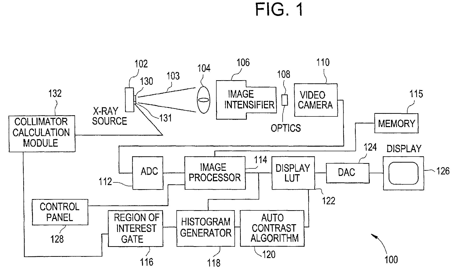
- Fig. 1 illustrates a fluoroscopic x-ray system that utilizes automatic contrast compensation in accordance with an embodiment of the present invention.
- the fluoroscopic system 100 includes an x-ray source 102 which directs an x-ray beam 103 toward a subject or patient 104.
- the patient 104 may be a human, animal, test phantom, or other object which includes anatomic structure.
- the image intensifier 106 detects the radiation that passes through the patient 104 and produces an image.
- the image is transferred via optics 108 to a CCD video camera 110.
- the CCD video camera 110 produces an analog video signal which is converted to a digital signal by an analog to digital converter (ADC) 112.
- ADC 112 may be included in the CCD video camera 110.
- the fluoroscopic system 100 includes a region of interest (ROI) gate 116, a histogram generator 118, and an auto contrast algorithm 120 that cooperate to perform automatic contrast compensation.
- ROI gate 116, histogram generator 118 and auto contrast algorithm 120 are displayed separately on Fig. 1 but may constitute software, all of which is performed by the image processor 114 or other component of the fluoroscopic system 100.
- separate hardware such as individual digital signal processing boards may carry out the functions of the ROI gate 116, histogram generator 118 and auto contrast algorithm 120.
- a control panel 128 may be utilized by an operator to input data, such as to enable automatic contrast compensation or enter patient data.
- a collimator 130 may be utilized to block a portion or portions of the x-ray beam 103.
- the collimator 130 may be comprised of one or more leaves.
- a detector 131 detects the position of the collimator 130.
- the collimator calculation module 132 reads the collimator position data and utilizes the collimator position data to calculate a region of interest.
- the region of interest may define an area of acquired data upon which a displayed image is based.
- the region of interest may be used by the ROI gate 116 to identify portions of the acquired data to block. Therefore, the blocked data may not affect the histogram generated by the histogram generator 118.
- the auto contrast algorithm 120 identifies maximum and minimum values in the histogram.
- Fig. 3 illustrates a histogram and a transfer function generated from a region of interest in accordance with an embodiment of the present invention.
- the histogram generator 118 utilizes the digital image data output from the image processor 114 inside the region of interest 144 over a raw data range 156 to generate a histogram 150.
- the digital image data used to construct histogram 150 does not include digital image data located in regions covered by collimator 130.
- the auto contrast algorithm 120 determines the detected minimum value (detected MIN) 152 and the maximum value (MAX) 154 within the histogram 150 of the digital image data.
- the display LUT 122 utilizes the detected MIN 152 and MAX 154 values to generate a transfer function 160 over the displayed contrast range 158.
- the display LUT 122 draws the transfer function 160 from the detected MIN 152 to the MAX 154 and translates the radiation levels of the histogram 150 to occupy the full contrast range of the display 126. Therefore, detected MIN 152 is typically assigned a value of zero or near zero on the vertical axis and MAX 154 is assigned a value of 255 on the vertical axis.
- the transfer function 160 may be stored in memory 115 and is illustrated as non-linear, but it should be understood that any transfer function may be used.
- the transfer function may be linear (such as the transfer function 184 illustrated in Fig. 5), logarithmic, exponential, S-shaped, hyperbolic tangent, or another shape that may not fit any mathematical model.
- the auto contrast algorithm 120 identifies the detected MIN 186 as the lowest detectable radiation.
- the display LUT 122 then generates the transfer function 184 based upon the detected MIN 186 and the MAX 190 with a displayed contrast range 192.
- the collimator data 176 and 178 is represented by the lower level of the transfer function 184, and subject data 168 is pushed into the upper level of the transfer function 184.
- the subject data 168 is displayed with contrast range 196, which is less than the displayed contrast range 192.
- the transfer function 226 maximizes the use of the displayed contrast range 228 by assigning collimator data 204 and 206 (data below MIN 222) a black or nearly black value.
- moderation values may be utilized by the auto contrast algorithm 120 to moderate the maximum and minimum values used by the display LUT 122.
- values below MIN 222 may be assigned a black, or nearly black, value, differentiating the data below MIN 222 from the anatomic data.
- the collimator leaves 254 and 256 may be rectangular in shape, resulting an a substantially rectangular exposure area 264. Alternatively, the collimator leaves 254 and 256 may be another shape to provide a circular, keyhole, or square exposure area 264, for example. By way of example only, the collimator leaves 254 and 256 may move toward and away from one another along a linear path 251, or may be rotated along a circular path 253.
- the collimator frame 258 may contain one or more position sensors 275-279 which sense the location of the collimator leaves 254 and 256.
- the position sensors 275-279 may be electromagnetic, mechanical, optical, or any other type of sensor.
- the collimator leaves 254 and 256 may be fixed to a specified position within frame 258, or may be adjusted by the operator to increase, decrease, or change the shape of the exposure area 264. It may be possible to move one collimator leaf 254 or 256, or the collimator leaves 254 and 256 may be fixed such that each collimator leaf 254 and 256 obstructs a substantially similar sized portion of the exposure area 264.
- one or more position sensors 275-279 within the collimator 250 sense the position of one or more collimator leaves 254 and 256.
- the collimator calculation module 132 reads position data from the position sensors 275-279 and utilizes the position data to calculate the position of the collimator leaves 254 and 256 relative to the x-axis 260 and y-axis 262.
- the position of the collimator leaves 254 and 256 may be identified by reading the location of one edge of a collimator leaf 254 or 256, such as marker 266 or 268.
- the collimator calculation module 132 may convert the position data to a numeric number set.
- the number set may comprise coordinate data, such as in a bit map, configured to store displayed digital image data.
- the collimator calculation module 132 may use the coordinate data to "draw" the location of each collimator leaf 254 and 256 into the bit map.
- the orientation of the collimator leaves 254 and 256 may be identified relative to a reference coordinate within the bit map.
- the shape of the collimator leaves 254 and 256 may also be identified. As discussed above, the shape of the collimator leaves 254 and 256 is not limited to a rectangle.
- the collimator calculation module 132 may calculate a region of interest 208, as illustrated in Fig. 6.
- the region of interest 208 is defined as a circle within the exposure area 264.
- the region of interest 208 may be any shape and/or size, and may be located anywhere within the exposure area 264.
- the region of interest 208 may include all digital image data within the exposure area 264. Therefore, all of the digital image data within the region of interest 208 may be utilized to adjust the contrast of the displayed diagnostic image 202.
- Fig. 9 illustrates a method for enhancing the contrast of diagnostic images acquired using automatic contrast compensation and a collimator in accordance with an embodiment of the present invention.
- the auto contrast option is enabled.
- the auto contrast option may be enabled through a keyboard or other control panel 128 as previously discussed.
- a look-up table used by the display LUT 122 to calculate the transfer function is predefined and may be stored in memory 115.
- the collimator calculation module 132 reads the collimator position information from the position sensors 275-279.
- the position of the collimator leaves 254 and 256 may be identified by one or more position sensors 275-279.
- the collimator position information may be in the form of a collimator marker 266-270, where one or more collimator markers 266-270 are used to identify the position, orientation, and shape of the collimator leaves 254 and 256.
Landscapes
- Engineering & Computer Science (AREA)
- Physics & Mathematics (AREA)
- General Physics & Mathematics (AREA)
- Theoretical Computer Science (AREA)
- Health & Medical Sciences (AREA)
- Life Sciences & Earth Sciences (AREA)
- Medical Informatics (AREA)
- Optics & Photonics (AREA)
- Heart & Thoracic Surgery (AREA)
- Nuclear Medicine, Radiotherapy & Molecular Imaging (AREA)
- Biophysics (AREA)
- Pathology (AREA)
- Radiology & Medical Imaging (AREA)
- Biomedical Technology (AREA)
- High Energy & Nuclear Physics (AREA)
- Molecular Biology (AREA)
- Surgery (AREA)
- Animal Behavior & Ethology (AREA)
- General Health & Medical Sciences (AREA)
- Public Health (AREA)
- Veterinary Medicine (AREA)
- Apparatus For Radiation Diagnosis (AREA)
Abstract
Description
Claims (10)
- An x-ray system (100), comprising:an x-ray source (102) irradiating a subject with x-rays;a collimator (130) located proximate said x-ray source (102) blocking a portion of said x-rays;a detector receiving x-rays from said x-ray source (102) and creating subject data (216) indicative of a subject and collimator data (204, 206) indicative of said collimator (130);a position detector (131) identifying a position of said collimator (130) with respect to a field of view of said x-ray source (102);a gating module receiving said subject (216) and collimator data (204, 206), said gating module at least passing a portion of said subject data (216), said gating module blocking at least a portion of said collimator data (204, 206) based on said position of said collimator (130); anda display (126) displaying an x-ray image (202) based at least on said portion of said subject data (216) passed by said gating module.
- The x-ray system (100) of claim 1, further comprising a histogram generator (118) creating a histogram (182) of said portion of said subject data (216), said histogram (182) affecting display of said x-ray image (202).
- The x-ray system (100) of claim 1, further comprising a histogram generator (118) creating a histogram (182) including said subject data (216) and excluding said collimator data (204, 206).
- The x-ray system (100) of claim 1, 2 or 3, further comprising a contrast module automatically adjusting contrast of said display independent of said collimator data (204, 206).
- An x-ray system (100), comprising:an x-ray source (102) irradiating a subject with x-rays;a collimator (130) located proximate said x-ray source (102) blocking a portion of said x-rays;a detector receiving x-rays from said x-ray source (102) and creating subject data (216) indicative of a subject and collimator data (204, 206) indicative of said collimator (130);a collimator calculation module (132) identifying at least one of a position, an orientation, a shape and a boundary (272, 274) of said collimator (130) based on said position of said collimator (130);a gating module receiving said subject (216) and collimator data (204, 206), said gating module at least passing a portion of said subject data (216), said gating module blocking at least a portion of said collimator data (204, 206) based on said position of said collimator (130); anda display (126) displaying an x-ray image (202) based at least on said portion of said subject data (216) passed by said gating module.
- The x-ray system (100) of claim 5, further comprising a histogram generator (118) creating a histogram (182) including said subject data (216) and excluding said collimator data (204, 206).
- The x-ray system (100) of claim 6, wherein said gating module blocks a section of said subject data (216) outside a region of interest (208).
- A method for enhancing the contrast of an x-ray image (202), the method comprising:exposing a subject to an x-ray source (102), said x-ray source (102) being partially blocked by a collimator (130);detecting subject data (216) indicative of a subject and collimator data (204, 206) indicative of the collimator (130);identifying position data indicative of a position of the collimator (130);gating said subject (216) and collimator data (204, 206) to block said collimator data (204, 206) based on said position data; anddisplaying an x-ray image (202) based on at least a portion of said subject data (216).
- The method of claim 8, said gating step further comprising blocking a portion of said subject data (216).
- The method of claim 8 or 9, further comprising automatically calculating minimum and maximum grayscale values based on at least a portion of said subject data (216), said minimum and maximum grayscale values utilized to display said x-ray image (202).
Applications Claiming Priority (2)
| Application Number | Priority Date | Filing Date | Title |
|---|---|---|---|
| US991050 | 1992-12-15 | ||
| US09/991,050 US6614877B2 (en) | 2001-11-21 | 2001-11-21 | Method and apparatus for enhancing the contrast of a medical diagnostic image acquired using collimation |
Publications (3)
| Publication Number | Publication Date |
|---|---|
| EP1321899A2 true EP1321899A2 (en) | 2003-06-25 |
| EP1321899A3 EP1321899A3 (en) | 2006-07-26 |
| EP1321899B1 EP1321899B1 (en) | 2009-02-04 |
Family
ID=25536806
Family Applications (1)
| Application Number | Title | Priority Date | Filing Date |
|---|---|---|---|
| EP02258040A Expired - Lifetime EP1321899B1 (en) | 2001-11-21 | 2002-11-21 | Method and apparatus for enhancing the contrast of a medical diagnostic image acquired using collimation |
Country Status (6)
| Country | Link |
|---|---|
| US (1) | US6614877B2 (en) |
| EP (1) | EP1321899B1 (en) |
| JP (1) | JP2003180667A (en) |
| KR (1) | KR20030041851A (en) |
| CN (1) | CN1419891A (en) |
| DE (1) | DE60231078D1 (en) |
Families Citing this family (26)
| Publication number | Priority date | Publication date | Assignee | Title |
|---|---|---|---|---|
| US7003145B2 (en) | 2001-01-05 | 2006-02-21 | Ge Medical Systems Global Technology Company, Llc. | Image cropping for asymmetrical imaging |
| JP4323770B2 (en) * | 2002-10-18 | 2009-09-02 | キヤノン株式会社 | Image processing apparatus, image processing method, program, and recording medium |
| JP2007506961A (en) * | 2003-09-24 | 2007-03-22 | コーニンクレッカ フィリップス エレクトロニクス エヌ ヴィ | Alignment method and apparatus for pixelated detector |
| US20060241370A1 (en) * | 2005-03-30 | 2006-10-26 | George Kramp | Medical x-ray imaging workflow improvement |
| US7133492B2 (en) * | 2004-03-30 | 2006-11-07 | Siemens Medical Solutions Usa, Inc. | Method for reducing radiation exposure during patient positioning |
| US7136455B2 (en) * | 2004-11-02 | 2006-11-14 | General Electric Company | Electron emitter assembly and method for adjusting a size of electron beams |
| US20070036266A1 (en) * | 2005-03-29 | 2007-02-15 | George Kramp | Medical x-ray imaging workflow improvement |
| US8983024B2 (en) | 2006-04-14 | 2015-03-17 | William Beaumont Hospital | Tetrahedron beam computed tomography with multiple detectors and/or source arrays |
| CN101466313B (en) * | 2006-04-14 | 2012-11-14 | 威廉博蒙特医院 | Scanning slot cone beam computed tomography and scanning focused spot cone beam computed tomography |
| US9339243B2 (en) | 2006-04-14 | 2016-05-17 | William Beaumont Hospital | Image guided radiotherapy with dual source and dual detector arrays tetrahedron beam computed tomography |
| CN101489477B (en) * | 2006-05-25 | 2011-08-03 | 威廉博蒙特医院 | Real-time, online and offline treatment dose tracking and feedback process for volumetric image-guided adaptive radiation therapy |
| US7869637B2 (en) * | 2006-07-31 | 2011-01-11 | Siemens Medical Solutions Usa, Inc. | Histogram calculation for auto-windowing of collimated X-ray image |
| US7344305B2 (en) * | 2006-08-01 | 2008-03-18 | Siemens Medical Solutions Usa, Inc. | Remote visual feedback of collimated area and snapshot of exposed patient area |
| KR100923624B1 (en) * | 2008-01-21 | 2009-10-23 | 고려공업검사 주식회사 | Radiographic Imaging Device Using CMOS Sensor |
| US8406518B2 (en) * | 2009-01-20 | 2013-03-26 | Pixar | Smoothed local histogram filters for computer graphics |
| JP5489577B2 (en) * | 2009-07-31 | 2014-05-14 | キヤノン株式会社 | Radiation imaging system and control method thereof, main control unit and control method thereof, and program |
| WO2011084878A1 (en) | 2010-01-05 | 2011-07-14 | William Beaumont Hospital | Intensity modulated arc therapy with continuous couch rotation/shift and simultaneous cone beam imaging |
| CN102753099B (en) * | 2011-01-07 | 2016-11-16 | 东芝医疗系统株式会社 | X ray CT device |
| KR101239765B1 (en) * | 2011-02-09 | 2013-03-06 | 삼성전자주식회사 | X-ray generating apparatus and x-ray imaging system having the same |
| JP5828649B2 (en) * | 2011-03-09 | 2015-12-09 | キヤノン株式会社 | Image processing apparatus, image processing method, and computer program |
| CN105101877A (en) * | 2012-11-29 | 2015-11-25 | 控制辐射系统有限公司 | X-ray reduction system |
| CN103192617B (en) * | 2013-04-03 | 2017-05-10 | 青岛大学附属医院 | Method for darkening X-ray image background and X-ray image printing system and printing method |
| KR102201407B1 (en) * | 2013-11-18 | 2021-01-12 | 삼성전자주식회사 | X-ray imaging apparatus and control method thereof |
| KR102393294B1 (en) * | 2014-09-26 | 2022-05-03 | 삼성전자주식회사 | Medical imaging devices and controlling method thereof |
| US10463323B2 (en) | 2014-10-13 | 2019-11-05 | Koninklijke Philips N.V. | Detector rotation controlled by X-ray collimation |
| JP6640470B2 (en) * | 2015-05-14 | 2020-02-05 | 株式会社日立製作所 | Radiation therapy system |
Family Cites Families (9)
| Publication number | Priority date | Publication date | Assignee | Title |
|---|---|---|---|---|
| US4489426A (en) | 1981-12-23 | 1984-12-18 | General Electric Company | Collimator with adjustable aperture |
| US5164993A (en) * | 1991-11-25 | 1992-11-17 | Eastman Kodak Company | Method and apparatus for automatic tonescale generation in digital radiographic images |
| US5436829A (en) | 1992-11-05 | 1995-07-25 | General Electric Company | Method of achieving reduced dose X-ray fluoroscopy by employing transform-based estimation of Poisson noise |
| JPH07250827A (en) * | 1994-03-11 | 1995-10-03 | Hitachi Medical Corp | X ray-image diagnosing apparatus |
| US5574764A (en) | 1995-06-06 | 1996-11-12 | General Electric Company | Digital brightness detector |
| US5901240A (en) * | 1996-12-12 | 1999-05-04 | Eastman Kodak Company | Method for detecting the collimation field in a digital radiography |
| JP3670439B2 (en) * | 1997-05-09 | 2005-07-13 | 株式会社日立メディコ | X-ray equipment |
| JP4383558B2 (en) * | 1998-07-21 | 2009-12-16 | 東芝医用システムエンジニアリング株式会社 | X-ray diagnostic apparatus and radiation diagnostic apparatus |
| US6175614B1 (en) * | 1999-05-07 | 2001-01-16 | Oec Medical Systems, Inc. | Method and apparatus for automatic sizing and positioning of ABS sampling window in an x-ray imaging system |
-
2001
- 2001-11-21 US US09/991,050 patent/US6614877B2/en not_active Expired - Lifetime
-
2002
- 2002-11-21 DE DE60231078T patent/DE60231078D1/en not_active Expired - Lifetime
- 2002-11-21 EP EP02258040A patent/EP1321899B1/en not_active Expired - Lifetime
- 2002-11-21 CN CN02150585A patent/CN1419891A/en active Pending
- 2002-11-21 KR KR1020020072803A patent/KR20030041851A/en not_active Withdrawn
- 2002-11-21 JP JP2002337729A patent/JP2003180667A/en active Pending
Also Published As
| Publication number | Publication date |
|---|---|
| DE60231078D1 (en) | 2009-03-19 |
| JP2003180667A (en) | 2003-07-02 |
| KR20030041851A (en) | 2003-05-27 |
| US6614877B2 (en) | 2003-09-02 |
| US20030095627A1 (en) | 2003-05-22 |
| EP1321899B1 (en) | 2009-02-04 |
| CN1419891A (en) | 2003-05-28 |
| EP1321899A3 (en) | 2006-07-26 |
Similar Documents
| Publication | Publication Date | Title |
|---|---|---|
| EP1321899B1 (en) | Method and apparatus for enhancing the contrast of a medical diagnostic image acquired using collimation | |
| US6370224B1 (en) | System and methods for the reduction and elimination of image artifacts in the calibration of x-ray imagers | |
| JP2001299733A (en) | Pci radiation beam image processing apparatus, pci radiation beam image detecting and processing apparatus, pci radiation beam image outputting apparatus and pci radiation beam image diagnosis supporting apparatus | |
| US6574307B1 (en) | Method and apparatus for enhancing the contrast of a medical diagnostic image that includes foreign objects | |
| US5978443A (en) | Automated removal of background regions from radiographic images | |
| US20100128063A1 (en) | Rendering for improved diagnostic image consistency | |
| US7869637B2 (en) | Histogram calculation for auto-windowing of collimated X-ray image | |
| US6744849B2 (en) | Image processing apparatus, image processing method, program, and storage medium | |
| JP2002162705A (en) | Phase contrast radiation image processor | |
| US7822255B2 (en) | Method and apparatus for generation of an x-ray image | |
| JP4307877B2 (en) | Image processing apparatus and image processing method | |
| JP4314001B2 (en) | Image display device | |
| WO2000032016A2 (en) | Method for automatic detection of region of interest for digital x-ray detectors using a filtered histogram | |
| JP3597272B2 (en) | Abnormal shadow candidate detection method | |
| US11707246B2 (en) | Method and apparatus for automatic determination of object and background region of interest for real-time automatic dose rate control in dynamic imaging systems | |
| EP1053659B1 (en) | An x-ray examination apparatus having an object absorption dependent brightness control | |
| EP1557791A1 (en) | Image processing method, and apparatus | |
| US6229875B1 (en) | Apparatus and method for providing an optimum brightness control signal for lung tissue X-ray images | |
| JP4336398B2 (en) | Radiation digital image processing system, radiation digital image processing apparatus, and radiation digital image processing method | |
| JP2002159477A (en) | Method of detecting suspicious region | |
| CN104680503A (en) | Medical image processing method, medical image processing device, and medical X-ray imaging equipment | |
| JP2001056854A (en) | Method and apparatus for determining the dynamic range of a medical digital image | |
| JPH078474A (en) | Shading correction device for medical diagnosis | |
| Schulerud et al. | Adaptive image content-based exposure control for scanning applications in radiography |
Legal Events
| Date | Code | Title | Description |
|---|---|---|---|
| PUAI | Public reference made under article 153(3) epc to a published international application that has entered the european phase |
Free format text: ORIGINAL CODE: 0009012 |
|
| AK | Designated contracting states |
Designated state(s): AT BE BG CH CY CZ DE DK EE ES FI FR GB GR IE IT LI LU MC NL PT SE SK TR |
|
| AX | Request for extension of the european patent |
Extension state: AL LT LV MK RO SI |
|
| PUAL | Search report despatched |
Free format text: ORIGINAL CODE: 0009013 |
|
| AK | Designated contracting states |
Kind code of ref document: A3 Designated state(s): AT BE BG CH CY CZ DE DK EE ES FI FR GB GR IE IT LI LU MC NL PT SE SK TR |
|
| AX | Request for extension of the european patent |
Extension state: AL LT LV MK RO SI |
|
| 17P | Request for examination filed |
Effective date: 20070126 |
|
| 17Q | First examination report despatched |
Effective date: 20070226 |
|
| AKX | Designation fees paid |
Designated state(s): DE FR IT NL |
|
| GRAP | Despatch of communication of intention to grant a patent |
Free format text: ORIGINAL CODE: EPIDOSNIGR1 |
|
| GRAS | Grant fee paid |
Free format text: ORIGINAL CODE: EPIDOSNIGR3 |
|
| GRAA | (expected) grant |
Free format text: ORIGINAL CODE: 0009210 |
|
| AK | Designated contracting states |
Kind code of ref document: B1 Designated state(s): DE FR IT NL |
|
| REF | Corresponds to: |
Ref document number: 60231078 Country of ref document: DE Date of ref document: 20090319 Kind code of ref document: P |
|
| PLBE | No opposition filed within time limit |
Free format text: ORIGINAL CODE: 0009261 |
|
| STAA | Information on the status of an ep patent application or granted ep patent |
Free format text: STATUS: NO OPPOSITION FILED WITHIN TIME LIMIT |
|
| 26N | No opposition filed |
Effective date: 20091105 |
|
| PGFP | Annual fee paid to national office [announced via postgrant information from national office to epo] |
Ref country code: DE Payment date: 20121128 Year of fee payment: 11 Ref country code: FR Payment date: 20121206 Year of fee payment: 11 |
|
| PGFP | Annual fee paid to national office [announced via postgrant information from national office to epo] |
Ref country code: IT Payment date: 20121126 Year of fee payment: 11 |
|
| PGFP | Annual fee paid to national office [announced via postgrant information from national office to epo] |
Ref country code: NL Payment date: 20121124 Year of fee payment: 11 |
|
| REG | Reference to a national code |
Ref country code: NL Ref legal event code: V1 Effective date: 20140601 |
|
| REG | Reference to a national code |
Ref country code: FR Ref legal event code: ST Effective date: 20140731 |
|
| REG | Reference to a national code |
Ref country code: DE Ref legal event code: R119 Ref document number: 60231078 Country of ref document: DE Effective date: 20140603 |
|
| PG25 | Lapsed in a contracting state [announced via postgrant information from national office to epo] |
Ref country code: NL Free format text: LAPSE BECAUSE OF NON-PAYMENT OF DUE FEES Effective date: 20140601 Ref country code: IT Free format text: LAPSE BECAUSE OF NON-PAYMENT OF DUE FEES Effective date: 20131121 Ref country code: DE Free format text: LAPSE BECAUSE OF NON-PAYMENT OF DUE FEES Effective date: 20140603 |
|
| PG25 | Lapsed in a contracting state [announced via postgrant information from national office to epo] |
Ref country code: FR Free format text: LAPSE BECAUSE OF NON-PAYMENT OF DUE FEES Effective date: 20131202 |