EP1321819A1 - Photographic processing apparatus and method - Google Patents
Photographic processing apparatus and method Download PDFInfo
- Publication number
- EP1321819A1 EP1321819A1 EP02080087A EP02080087A EP1321819A1 EP 1321819 A1 EP1321819 A1 EP 1321819A1 EP 02080087 A EP02080087 A EP 02080087A EP 02080087 A EP02080087 A EP 02080087A EP 1321819 A1 EP1321819 A1 EP 1321819A1
- Authority
- EP
- European Patent Office
- Prior art keywords
- film
- drum
- disk
- processing
- circular
- Prior art date
- Legal status (The legal status is an assumption and is not a legal conclusion. Google has not performed a legal analysis and makes no representation as to the accuracy of the status listed.)
- Withdrawn
Links
- 238000000034 method Methods 0.000 title claims abstract description 37
- 238000012545 processing Methods 0.000 title claims description 165
- 238000001035 drying Methods 0.000 claims abstract description 12
- 238000011068 loading method Methods 0.000 claims description 55
- 230000007246 mechanism Effects 0.000 claims description 29
- 230000008569 process Effects 0.000 claims description 25
- 238000012546 transfer Methods 0.000 claims description 16
- 239000012530 fluid Substances 0.000 claims description 13
- 230000008859 change Effects 0.000 claims description 4
- 238000007599 discharging Methods 0.000 claims 1
- 239000000243 solution Substances 0.000 description 33
- 239000000126 substance Substances 0.000 description 32
- 241000842962 Apoda limacodes Species 0.000 description 22
- 239000007844 bleaching agent Substances 0.000 description 6
- 238000013461 design Methods 0.000 description 6
- 239000002699 waste material Substances 0.000 description 6
- 238000012993 chemical processing Methods 0.000 description 4
- 239000002894 chemical waste Substances 0.000 description 4
- 238000005520 cutting process Methods 0.000 description 4
- 230000000087 stabilizing effect Effects 0.000 description 4
- 230000008901 benefit Effects 0.000 description 3
- 238000012423 maintenance Methods 0.000 description 3
- 238000003860 storage Methods 0.000 description 2
- XLYOFNOQVPJJNP-UHFFFAOYSA-N water Substances O XLYOFNOQVPJJNP-UHFFFAOYSA-N 0.000 description 2
- 230000004308 accommodation Effects 0.000 description 1
- 230000004075 alteration Effects 0.000 description 1
- 238000007664 blowing Methods 0.000 description 1
- 238000011161 development Methods 0.000 description 1
- 238000010790 dilution Methods 0.000 description 1
- 239000012895 dilution Substances 0.000 description 1
- 238000010981 drying operation Methods 0.000 description 1
- 230000005611 electricity Effects 0.000 description 1
- 239000000284 extract Substances 0.000 description 1
- 238000000605 extraction Methods 0.000 description 1
- 238000004519 manufacturing process Methods 0.000 description 1
- 238000005259 measurement Methods 0.000 description 1
- 238000012552 review Methods 0.000 description 1
- 238000005406 washing Methods 0.000 description 1
Images









Classifications
-
- G—PHYSICS
- G03—PHOTOGRAPHY; CINEMATOGRAPHY; ANALOGOUS TECHNIQUES USING WAVES OTHER THAN OPTICAL WAVES; ELECTROGRAPHY; HOLOGRAPHY
- G03D—APPARATUS FOR PROCESSING EXPOSED PHOTOGRAPHIC MATERIALS; ACCESSORIES THEREFOR
- G03D3/00—Liquid processing apparatus involving immersion; Washing apparatus involving immersion
- G03D3/02—Details of liquid circulation
- G03D3/04—Liquid agitators
Definitions
- the present invention is directed to a photographic processor and method of operation.
- Photographic processors come in a variety of shapes and sizes from large wholesale photographic processors to small micro-labs. As photographic processors become more and more technologically sophisticated, there is a continued need to make the photographic processor as user-friendly and as maintenance-free as possible.
- a portable photographic processor which provides exceptional print quality while requiring a minimal number of tasks necessary for an operator to process a roll of film.
- a portable photographic processor which is designed to efficiently process a roll of film while minimizing the amount of waste generated during the photographic process.
- the present invention addresses some of the difficulties and problems discussed above by the discovery of a novel, compact, and portable photographic processor having an internal drum design, which minimizes the chemicals required to process a roll of film and consequently minimizes the amount of waste generated per roll of film processing.
- the photographic processor is extremely user-friendly and low maintenance.
- the present invention is directed to a photographic processor and a method of processing film using the photographic processor.
- the present invention is further directed to individual processor components within the photographic processor, such as the drum itself, the film loading system, and other components.
- the present invention is directed to photographic processors.
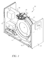
- An exemplary photographic processor of the present invention is shown in FIG. 1.
- the photographic processor 10 comprises at least an outer housing, which includes a first side wall 11, a base housing member 12, and second side wall 13.
- the photographic processor 10 includes a circular processing chamber 14 (also referred to herein as the "circular processing drum 14"), which may be used to expose a given strip or roll of film to one or more photoprocessing chemicals.
- Photographic processor 10 further includes a film-loading/unloading device 15 positioned above and cooperating with circular processing drum 14.
- a chemical delivery system 16 is positioned for easy access by a user (i.e., for maintenance or replacement purposes) at a location near side wall 13 and base housing member 12.
- Photographic processor 10 also includes a circular dryer 17 in the form of, for example, a cylinder, for drying the processed film. Dryer 17 is concentrically and co-axially positioned around processing drum 14. Once a given strip or roll of film is dried in dryer 17, the film proceeds to a scanner 18', which may be positioned above chemical delivery system 16 in a space bordered by side wall 13 and left interior wall 18 or any other convenient location.
- a scanner 18' which may be positioned above chemical delivery system 16 in a space bordered by side wall 13 and left interior wall 18 or any other convenient location.
- FIG. 2 depicts a rear view of photographic processor 10.
- photographic processor 10 includes opening 19 in side wall 13 for accessing chemical delivery system 16.
- Sliding track mechanism 20 allows an operator to pull at least a portion of chemical delivery system 16 through opening 19 to an exterior location outside of photographic processor 10.
- Photographic processor 10 can include a waste collection reservoir 21, which collects and stores used processing chemicals removed from circular processing drum 14 following development of a given strip or roll of film.
- dryer 17 includes dryer entrance 171 and dryer blower 172. The various components of photographic processor 10 will be described in more detail below with reference to FIGS. 3-21.
- Circular processing drum 14 is further described in FIG. 3. As shown in FIG. 3, circular processing drum 14 includes a first wall 141, a second wall 142, a side wall 143, and a central axis opening 144. A portion of a drum and disk drive mechanism 25 (shown in FIGS. 2, 8 and 9) passes through central access opening 144. Circular processing drum 14 comprises two circular sections joined together at multiple locations around the perimeter of circular processing drum 14 via male clasping members 145 and female clasping members 146. It should be noted that any means for attaching the two circular components of circular processing drum 14 may be used in place of male clasping members 145 and female clasping members 146.
- circular processing drum 14 may also consist of a single component as oppose to two circular components as shown in FIG. 3, although such a design may add manufacturing cost to circular processing drum 14.
- Circular processing drum 14 further comprises a film cartridge loading area 147 on an outer surface of side wall 143 for loading film directly from a film cartridge into circular processing drum 14, such as with APS film.
- Circular processing drum 14 also comprises a film input slot 148, which enables the entry and exit of film into circular processing drum 14.
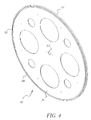
- FIG. 4 depicts an exemplary disk 30, which is positioned within circular processing drum 14, and functions to convey film within circular processing drum 14 once the film enters through film input slot 148.
- Disk 30 includes a first face 31, a second face 32, a central access opening 33, an outer perimeter 34, and one or more sets of disk teeth 35 located along outer perimeter 34 of disk 30.
- a portion of drum and disk drive mechanism 25 may extend into central access opening 33 to engage with and cause rotation of disk 30.
- FIG. 5 provides a close-up view of a portion of disk 30, and in particular, outer perimeter 34 and a set of disk teeth 35 on the outer perimeter 34 of disk 30.
- the outermost points of disk teeth 35 are in close proximity to an inner surface of side wall 143 of circular processing drum 14.
- disk teeth 35 could be spring loaded through the use of springs 35a.
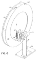
- roller arrangement 27 (Figs. 6 and 7) is positioned within circular processing drum 14.
- Roller arrangement 27 includes a roller 270 having interengaging members 277 and 278 (Fig. 7).
- Roller arrangement 27 may be supported by a support member 28, which is attached to a support member base 29.
- Support member base 29 may be permanently or temporarily attached to base housing member 12 (shown in FIGS. 1 and 2).
- Roller arrangement 27 includes a motor 271, which provides motion to pistons 272 through openings 273 in a fixed positioning member 274. Pistons 272 proceed through stationary positioning support member 276 and are attached to movable positioning support member 275.
- movable positioning support member 275 which is coupled to member 277 separates from stationary positioning support member 276 which is coupled to member 278. This permits roller 270 to be expandible between a first width when the members 277 and 278 overlap each other and a second width larger than the first width (Fig. 7) when the members 277 and 278 move away from each other.
- FIG. 7 provides a detailed view of roller arrangement 27 and its various components.
- movable positioning support member 275 and stationary positioning support member 276 connect to interengaging members 277 and 278 respectively as described above.
- the film passes between roller 270 and an interior surface of drum 14.
- Roller 270 is freely rotatable and maintains the film flat along the lower portion of drum 14.
- roller 270 further provides an agitating feature within processing drum 14 during processing.
- the width of roller 270 is adjustable as described above to accommodate a shorter width film (i.e. APS film) and a larger width film (i.e. 35mm film).
- roller arrangement 27 including roller 270 can be vertically adjustable to accommodate for film curl as the film passes between roller 270 and the interior surface of drum 14.
- roller 270 can be spring loaded so as to accommodate any variation in the interior surface of drum 14.
- circular processing drum 14 is connected to a drum and disk drive mechanism 25, which selectively rotates disk 30 relative to drum 14 to position and convey the film along and within processing drum 14, and rotates both disk 30 and drum 14 together during a processing cycle.
- Circular processing drum 14 rotates about an axis of symmetry.
- An exemplary drum and disk drive mechanism 25 is shown in FIG. 8.
- Drum and disk drive mechanism 25 cooperates with a motor 22, a belt 23, and a pulley 24 as shown in FIGS. 8 and 9A.
- Drum and disk drive mechanism 25 includes a drive shaft 261 which is operationally connected to pulley 24. Also shown in Figs. 8 and 9A are flanges 251 and 252.
- Flange 251 is connected to drum 14 while an end cap 300 holds disk 30 for rotation about drive shaft 261 (Fig. 9A).
- Actuation of motor 22 drives belt 23 which in turn drives pulley 24. This in turn causes a rotation of drive shaft 261 which rotates disk 30.
- Clutch mechanism 250 enables the engagement and disengagement of flange 251 to provide selective rotation to circular processing drum 14.
- FIG. 9A displays a cross-sectional view of drum and disk drive mechanism 25 and clutch mechanism 250 along line 9A-9A in FIG. 8.
- Fig. 9A and Fig. 9B which is a schematic representation of the driving and clutching feature of the present invention
- an operation will now be described.
- clutch 250 is deactivated as shown in Fig. 9B.
- rotation of motor 22 will cause a rotation of drive shaft 261 and accordingly, a rotation of disk 30 relative to drum 14.
- clutch 250 is deactivated and therefore, drum 14 is not rotated. This permits the conveyance of the film by rotation of disk 30 to a desired location within drum 14.
- clutch 250 is activated, (for example, clutch 250 is moved to the right in Fig. 9B) by actuating clutch 250 with flange 251 which is attached to drum 14. Therefore, a rotation of motor 22 will cause a rotation of both disk 30 and drum 14. This occurs during the processing stages to process the film in a manner which will be described later.
- drive shaft 261 can be moved perpendicularly and through flange 251 and flange 252 to move disk 30 attached thereto.
- drive shaft 261 is attached to a fitting 264 in a manner which permits drive shaft 261 to rotate relative to fitting 264.
- Fitting 264 is in turn rotatably attached to a pivotable arm 262 and a movable member 263.
- Movable member 263 can be operationally connected to a motor for rotation of member 263. This causes arm 262 to pivot about point 262' to move drive shaft 261 to the left or right when viewing Fig. 9A from above the page.
- Movement of drive shaft 261 moves disk 30 in a direction parallel to an axis of disk 30. This facilitates the accommodation of, for example, 35mm and APS film on disk 30, since the disk 30 can be moved based on the type of film being processed.
- a film may be loaded into circular processing drum 14 by a number of methods.
- One method of loading film, such as APS film, into circular processing drum 14 is shown in FIGS. 10-13.
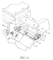
- film cartridge 40 comprising a film cartridge spool 41 and film cartridge door opening mechanism 52 is positioned in a film cartridge loading area 147 located on side wall 143 of circular processing drum 14.
- Film (not shown) exiting film cartridge 40 enters circular processing drum 14 at light tight film input slot 148 (Fig. 3) in side wall 143 of circular processing drum 14.
- a film cartridge stabilizing member 50 applies an amount of pressure onto an upper surface of film cartridge 40 to prevent film cartridge 40 from moving while positioned in film cartridge loading area 147.
- Spool engaging member 51 and cartridge door opening mechanism engaging member 52 move toward film cartridge 40 and engage with film cartridge spool 41 and film cartridge door 42, respectively.
- Door opening mechanism engaging member 52 opens film cartridge mechanism 42 and spool engaging member 51 begins to rotate film cartridge spool 41, forcing film (not shown) out of film cartridge 40.
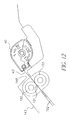
- FIG. 12 shows a strip of film 43 exiting film cartridge 40 and entering film input slot 148 of circular processing drum 14.
- nip rollers 150 grasp a leading edge of the strip of film 43 at drum roller nip point 151 and advance film 43 further into circular processing drum 14.
- the strip of film 43 exits drum cavity slot 152 and enters into the drum processing cavity 1521 of circular processing drum 14, wherein one or more sets of disk teeth 35 on disk 30 interengage with holes or perforations along an edge of the strip of film 43.
- disk teeth 35 could be spring loaded so as to spring up at the appropriate time and interengage with the holes or perforations along film 43.
- clutch 250 disengaged, disk 30 and rollers 150 are rotated while circular processing drum 14 remains stationary.
- a number of commercially available films may be loaded according to the film-loading method described above, namely, wherein the film remains intact with its corresponding film cartridge during processing.
- a suitable film which may be used in this particular film-loading method, includes, but is not limited to, APS film.
- APS film is loaded into the photographic processor of the present invention according to this method.
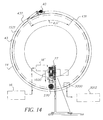
- FIG. 14 depicts circular processing drum 14 fully loaded with film 43 having a forward end 431 and a rearward end 432 within the drum processing cavity 1521 of circular processing drum 14. The back end of film 43 is maintained in cartridge 40. Film 43 is now positioned within circular processing drum 14 for chemical processing, wherein one or more processing fluids are deposited into circular processing drum 14 and placed in contact with film 43 for a desired period of time.
- a section of drum 14 will not have film therein. This is referred to as a film-free zone 431' (Fig. 14).
- clutch 250 Prior to delivering chemistry by way of chemical supply 16 and a chemical delivery mechanism 16' (Fig. 14), clutch 250 is activated or engaged and drum 14 is controllably rotated with disk 30 so that film-free zone 431' is at a lower end or below chemical delivery mechanism 16'.
- Chemical delivery mechanism 16' is preferably of the type which drops or delivers chemistry into drum 14 in the direction of arrow 1600 (Fig. 14).
- film transfer arm assembly 60 is positioned to move or pivot between circular processing drum 14 and dryer 17.
- Film transfer arm assembly 60 includes a lower arm member 61, which is rotatable around an axis of symmetry 153 of circular processing drum 14.
- Film transfer arm assembly 60 also includes an upper arm member 62, which is pivotally attached to lower arm member 61.
- film transfer arm assembly 60 includes a film cartridge gripper 64 and film strip gripper rolls 65.
- Fig. 15B which is a front view of the entrance of dryer 17, a side wall of dryer 17 includes a slot 1700 with a rubber seal that extends along the length of the dryer.
- Upper arm member 62 includes a shaft 620 which extends from upper arm member 62, through slot 1700 and is connected to gripper 64. This permits transfer arm assembly 60 to pull gripper 64 and thus the film to be dried though the dryer.
- film cartridge gripper 64 of film transfer arm assembly 60 engages with film cartridge 40, pulls film cartridge 40 from loading area 147 and the strip of film 43 from circular processing drum 14 in direction 600a, and proceeds through dryer 17 in direction 600b. Therefore, cartridge 40 with processed film 43 attached and trailing therefrom is conveyed through dryer 17 to dry film 43 by, for example, the blowing of air into dryer 17.
- film sheet gripper rolls 65 grip an edge of film 43 as film 43 exits film input slot 148 of circular processing drum 14. Film sheet gripper rolls 65 of film transfer arm assembly 60 pull film 43 from circular processing drum 14 and proceeds through dryer 17. Once dried, film 43 is re-wound back into its cartridge 40 prior to proceeding to scanner 18'.
- film loading/unloading device 15 includes a film cartridge loading area 154, which can be enclosed by closing a door 158.
- Film loading area 154 an operator extracts the tongue of film 43' from cartridge 40' and engages the perforations on film 43' with sprockets on a driven roller 1570. Thereafter door 158 is closed and film 43' proceeds into festoon box 155 through festoon box nip rollers 156.
- a cutter 157 slices film 43' to separate film 43' from film cartridge 40'.
- Any counter device (not shown) may be used to measure the length of the strip of film 43' passing through festoon box nip rollers 156. The length measurement is used in further processing steps as described below.
- FIG. 17 depicts a cross-sectional view of film loading/unloading device 15 as seen along line 17-17 in FIG. 16.
- film cartridge 40' is positioned in film cartridge loading area 154 while a strip of film 43' is removed from film cartridge 40' and transported to festoon box 155 where it is turned.
- a reverse roll of film 431 is formed from the film 43' in festoon box 155.
- a lead end of film 432 becomes the innermost portion of the reverse roll 431 while a tail end of film 433 becomes the outermost portion of reversed roll 431.
- tail end 433 which contains the last exposures on the strip of film 43', is fed into circular processing drum 14 first.
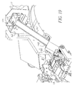
- a film-loading guide 159 is used to load reverse roll 431 into circular processing drum 14 as shown in FIG. 18.
- Festoon box 155 rotates from an initial position (as shown in FIGS. 16 and 17) to a film-loading position as shown in FIG. 18.
- Festoon box nip rollers 156 turn to advance tail end 433 of reverse roll 431 into film-loading guide 159 at guide entrance slot 1591.
- the film 43' exits the film-loading guide 159 at guide exit slot 1592 positioned adjacent to film input slot 148 of circular processing drum 14.
- driven nip rollers 150 grab the film 43' and advance the film 43' into circular processing drum 14 as described above.
- nip rollers 150 are programmed to advance the film 43' into circular processing drum 14 a specific length, which corresponds to the length of film inputted into festoon box 155 and measured via festoon box nip rollers 156 as described above.
- nip rollers 150 advance the strip of film 43' into circular processing drum 14 so that lead end 432 of film 43' remains nipped between nip rollers 150 during chemical processing (i.e., lead end 432 of the strip of film 43' does not enter into drum processing cavity 1521). This permits all of the exposed areas of the film 43' to be in the processing area in the drum.
- film 43' is transferred to dryer 17 by film transfer arm assembly 60 as described above.
- the strip of film 43' is pulled from circular processing drum 14 through film input slot 148 by film sheet gripper rolls 65 attached to upper transfer arm member 62.
- Nip rollers 150 provide a first end (corresponding to lead end 432) to film sheet gripper rolls 65.
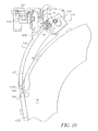
- film sheet gripper rolls 65 are shown positioned at dryer entrance 171. From this position, film sheet gripper rolls 65 proceed through dryer 17 pulling the film 43' through dryer 17.
- upper film transfer arm member 62 exits dryer 17 at dryer exit 173 and comes into contact with a conduit 70. Film sheet gripper rolls 65 turn to advance the film 43' through conduit 70 and into scanner festoon box 71.
- Scanner festoon box nip rollers 72 grasp a leading edge of film 43' and force film 43' into scanner festoon box 71 forming scanner film roll 435. Scanner festoon box nip rollers 72 advance film 43' into scanner festoon box 71 a specific distance equal to the predetermined length of film 43' so that the tail end of film 43' remains nipped between scanner festoon box nip rollers 72 to go to the scanner.
- film 43' may be further processed by transporting the film 43' to scanner 18'.
- scanner festoon box 71 rotates from an initial position (as shown in FIG. 20) to a secondary position so that the film 43' may be fed to scanner 18'.
- Scanner 18' may supply image data to computer 2000 or a remote computer (not shown) for further image processing.
- the film 43' may be packaged as a film roll or as strips of film and returned to the customer along with scanned photographs in electronic format on an electronic disc if desired.
- a number of commercially available films may be loaded according to the film-loading method described above, namely, wherein the film is separated from its corresponding film cartridge during processing.
- Suitable films which may be used in this particular film-loading method, include, but are not limited to, 135 mm film. Desirably, 135 mm film is loaded into the photographic processor of the present invention according to this method.
- the photographic processor of the present invention may be used to process one or more types of film. Suitable films include, but are not limited to, APS film, 135 mm film, etc. Desirably, the photographic processor of the present invention is designed to process APS film, 135 mm film, or both APS and 135 mm film.
- the photographic processor of the present invention may be categorized as a "single-roll" processing unit given that the circular processing drum only processes one roll of film at a time. However, it should be noted that the photographic processor of the present invention is capable of processing multiple rolls of film at a given time. For example, one roll of film may be in the circular processing drum, while a second roll of film is in the dryer and a third roll of film is in the scanner.
- the photographic processor of the present invention may include other components other than those described in FIGS. 1-21.
- the photographic processor of the present invention may include an operator interface control panel operationally associated with computer 2000 (Fig. 1); a display screen; a control unit, wherein the control unit accepts input from a processor user, provides machine settings to one or more components of the processor based on the input of the user, and controls and executes a processing operation of the processor; and multiple film loading doors on an outer surface of the photographic processor housing.
- the photographic processor is used to process APS film and 135 mm film.
- the photographic processor has two separate film loading doors on an outer surface of the photographic processor housing, one for an APS film cartridge and the other for a 135 mm film cartridge.
- the photographic processor of the present invention may come in a variety of sizes depending on a number of factors including, but not limited to, the desired size of the circular processing drum, the desired storage capacity of the chemical delivery system, and the desired storage capacity of the waste collection reservoir.
- One of the benefits of the photographic processor of the present invention is the ability to place the photographic processor in a given room without occupying a large amount of space.
- Another benefit of the photographic processor of the present invention is that the only requirement necessary to operate the photographic processor in a given room is a source of electricity. Since the photographic processor of the present invention can operate with working strength chemistry, the processor does not require a water source or drain for processing chemicals. A minimum amount of processing chemicals is needed to operate the photographic processor of the present invention due to the unique design of the circular processing drum. Further, a minimum amount of chemical waste is generated due to the design of the circular processing drum.
- the circular processing drum of the photographic processor may vary in size depending on a number of factors including, but not limited to, the type of film processed, the length of the film processed, the width of the film processed, and the desired overall dimensions of the photographic processor.
- the length of the drum i.e., the dimension perpendicular to the diameter of the drum
- the drum has a circumference, which is slightly greater than largest length of the roll film.
- the photographic processor comprises (1) a circular processing drum having a front wall, a back wall, a side wall connecting the front wall to the back wall and extending around a perimeter of the drum, and a horizontally extending axis of symmetry, wherein the diameter of the drum is greater than a length of the drum, which is measured along the axis of symmetry; (2) a disk positioned inside the drum in a plane parallel to both the front wall and the back wall, wherein the disk comprises one or more sets of disk teeth along an outer perimeter of the disk capable of interengaging with holes along a first edge of a sheet of processible film; and (3) a mechanism for rotating the disk while the drum is stationary.
- the mechanism for rotating the disk may be capable of rotating the disk and the drum simultaneously, or selectively rotating only the disk.
- the mechanism for rotating the disk may comprise a number of components including, but not limited to, a motor, a clutch, and a drive axis, wherein the drive axis is positioned along the axis of symmetry of the drum.
- the circular processing drum and/or the disk may be rotated at a speed depending on a number of factors including, but not limited to, the type of film, the size of the circular processing drum, the desired amount of contact time between each of the one or more processing solutions and the roll of film, and the desired speed at which film is introduced into the circular processing drum.
- the photographic processor comprises a circular processing drum, wherein the circular processing drum comprises a disk having one or more sets of teeth.
- the one or more sets of teeth interengage with holes along the film to pull the film into the circular processing drum.
- the photographic processor of the present invention may use any conventional chemical delivery system known in the art as long as the chemical delivery system is capable of inputting one or more processing fluids into the circular processing drum. Suitable chemical delivery systems deliver one or more processing fluids including, but not limited to, a developing solution, a bleach solution, a fix solution, a wash solution, or a combination thereof. Desirably, the chemical delivery system comprises one or more separate containers for each of the processing fluids.
- the chemical delivery system may comprise one or more separate containers containing a developing solution, one or more separate containers containing a bleach solution, one or more separate containers containing a fix solution, and one or more separate containers containing a wash solution.
- the chemical delivery system used in the photographic processor comprises one container of developing solution, one container of bleach solution, one container of fix solution, and at least one container of wash solution.
- the photographic processor of the present invention utilizes a chemical delivery system comprising "working strength" chemical solutions.
- working strength is used to describe chemical solutions, which are prepackaged in separate containers at concentrations that do not require dilution with other solutions (i.e., a source of water), and can be used as is.
- the photographic processor of the present invention may use any conventional chemical removal system to remove one or more processing fluids from the circular processing drum.
- Suitable chemical removal systems include, but are not limited to, a suction device or a drain 3000 (Fig. 14) in the side wall of the circular processing drum.
- the chemical removal system further comprises a chemical waste reservoir 3002 (Fig. 14) for storing one or more processing fluids removed from the drum.
- the chemical waste reservoir is designed to contain all of the waste resulting from the use of all of the processing fluids contained in the chemical delivery system.
- the photographic processor of the present invention uses a minimum amount of photoprocessing chemicals, and consequently generates a minimum amount of chemical waste.
- the dryer of the invention should be capable of drying the processed film.
- the dryer may use air and/or radiant heat to dry the processed film.
- the dryer has a capacity, which minimizes the amount of dwell time within the dryer.
- the photographic processor of the present invention may include a film-loading device, wherein the film loading device comprises one or more of the following components: (a) a film cartridge stabilizing bar for fixing a position of a film cartridge in a film cartridge loading area on an outer surface of the side wall; (b) a film cartridge door opening device; (c) a film cartridge spool turning device; (d) a festoon box for storing film removed from a film cartridge; (e) a cutting device for cutting film to separate the film from a film cartridge; and (f) a festoon box nip rollers for gripping film.
- the film-loading device comprises all of the above components.
- the photographic processor comprises (1) a circular processing drum having a front wall, a back wall, a side wall connecting the front wall to the back wall and extending around a perimeter of the drum, and a horizontally extending axis of symmetry, wherein the diameter of the drum is greater than a length of the drum, which is measured along the axis of symmetry of the drum; (2) a disk positioned inside the drum in a plane parallel to both the front wall and the back wall, wherein the disk comprises one or more sets of disk teeth along an outer perimeter of the disk capable of interengaging with holes along a an edge of a strip of processible film; and (3) a disk positioning device, wherein the disk positioning device moves the disk within the drum to change a distance between the disk and the front wall of the drum.
- the photographic processor may further comprise a mechanism (a) for rotating the disk and the drum simultaneously, and (b) for rotating the disk while the drum is stationary.
- the present invention is further directed to a photographic process, wherein the process comprises the steps of: (1) loading a sheet of processible film into a circular processing drum, wherein the circular processing drum comprises (a) a front wall, (b) a back wall, (c) a side wall connecting the front wall to the back wall and extending around a perimeter of the drum, and (d) a horizontally extending axis of symmetry, wherein the drum has a diameter greater than a length of the drum, the length of the drum being measured along the axis of symmetry of the drum, and wherein the drum contains a disk positioned inside the drum in a plane parallel to both the front wall and the back wall, wherein the disk comprises one or more sets of disk teeth along an outer perimeter of the disk capable of interengaging with holes along a first edge of the sheet of processible film; (2) contacting the sheet of processible film with one or more processing fluids in the circular processing drum; (3) rotating the circular processing drum along the axis of symmetry for a period of time; (4) removing
- the loading step may comprise one or more of the following steps: (i) feeding the sheet of processible film into the circular processing drum through a film-loading slot in the side wall of the drum; (ii) nipping the sheet of processible film to move the sheet of processible film into contact with the one or more sets of disk teeth along the disk; and (iii) rotating the disk while the drum remains stationary to advance the sheet of processible film into the circular processing drum.
- the photographic process of the present invention may comprise contacting a strip of film with one or more processing fluids selected from a developing solution, a bleach solution, a fix solution, a wash solution, or a combination thereof.
- the photographic process comprises a contacting step, which comprises (i) inputting a developing solution into the circular processing drum; (ii) inputting a bleach solution into the circular processing drum; (iii) inputting a fix solution into the circular processing drum; and (iv) inputting at least one wash solution into the circular processing drum.
- the contacting step of the process may further comprise separate removal steps following a washing solution input step.
- the process may comprise inputting a developing solution into the drum; inputting a fix solution into the drum; inputting a bleach solution into the drum; and inputting at least one wash solution into the drum.
- the photographic process of the present invention may further comprise a rotating step, wherein the rotating step comprises rotating the drum and the disk simultaneously.
- the drum and the disk may be simultaneously rotated after each processing solution input step for a period of time in order to insure a desired amount of contact between each processing solution and the film.
- the photographic process of the present invention may comprise a series of processing steps, wherein the film remains intact with its corresponding film cartridge (for example, APS film).
- the photographic process of the present invention comprises removing the processible film from a film cartridge (i.e. 35 mm film), and cutting the processible film to separate the processible film from the film cartridge When the film is to remain intact with its film cartridge (i.e.
- the photographic process of the present invention may comprise one or more of the following film loading steps: (a) positioning a film cartridge containing the strip of processible film in a film cartridge loading area on an outer surface of the side wall; (b) applying a film cartridge stabilizing bar to an upper surface of the film cartridge to secure the film cartridge; (c) opening a door of the film cartridge; and (d) turning a spool within the film cartridge.
- film loading steps (a) positioning a film cartridge containing the strip of processible film in a film cartridge loading area on an outer surface of the side wall; (b) applying a film cartridge stabilizing bar to an upper surface of the film cartridge to secure the film cartridge; (c) opening a door of the film cartridge; and (d) turning a spool within the film cartridge.
- the photographic process of the present invention may comprise one or more of the following film loading steps: (a) positioning a film cartridge containing the strip of processible film in a film cartridge loading area adjacent to a festoon box; (b) pulling a tongue on the film from the film cartridge using, for example, a film extraction tool; (c) engaging perforations on the film on a sprocket wheel; (d) transferring the film from the film cartridge to the festoon box to form a roll of film; wherein a last exposure on the film is on an outer portion of the roll of film; and (e) cutting the film to separate the film from the film cartridge.
- the present invention is directed to a photographic process which comprises moving a disk within a circular processing drum along an axis of symmetry of the drum to change a distance between the disk and a wall, such as the front wall, of the drum.
- the photographic process is capable of processing different types of film using the same circular processing drum by adjusting the position of the disk within the circular processing drum.
Landscapes
- Physics & Mathematics (AREA)
- General Physics & Mathematics (AREA)
- Photographic Processing Devices Using Wet Methods (AREA)
- Photographic Developing Apparatuses (AREA)
Abstract
A photographic processor and method of operation is disclosed.
The processor includes a circular drum (14) and a disk (30) positioned inside the
drum. The disk comprises at least one set of teeth along an outer periphery
thereof for engagement with perforations on film. The processor also includes a
circular dryer (17) for drying the processed film. The dryer extends around an
outer periphery of the drum.
Description
- The present invention is directed to a photographic processor and method of operation.
- Photographic processors come in a variety of shapes and sizes from large wholesale photographic processors to small micro-labs. As photographic processors become more and more technologically sophisticated, there is a continued need to make the photographic processor as user-friendly and as maintenance-free as possible.
- Currently available photographic processors have one or more of the following shoutcomings: (1) the film processing time is relatively high; (2) some photographic processors, because of their size, require a large amount of space; (3) some photographic processors may require an unacceptable amount of developing solution due to the design of the processing tank; and (4) some photographic processor generate an unacceptable amount of developing solution waste due to the design of the processing tank.
- What is needed in the art is a portable photographic processor, which provides exceptional print quality while requiring a minimal number of tasks necessary for an operator to process a roll of film. What is also needed in the art is a portable photographic processor, which is designed to efficiently process a roll of film while minimizing the amount of waste generated during the photographic process.
- The present invention addresses some of the difficulties and problems discussed above by the discovery of a novel, compact, and portable photographic processor having an internal drum design, which minimizes the chemicals required to process a roll of film and consequently minimizes the amount of waste generated per roll of film processing. The photographic processor is extremely user-friendly and low maintenance.
- Accordingly, the present invention is directed to a photographic processor and a method of processing film using the photographic processor. The present invention is further directed to individual processor components within the photographic processor, such as the drum itself, the film loading system, and other components.
- These and other features and advantages of the present invention will become apparent after a review of the following detailed description of the disclosed embodiments and the appended claims.
- The present invention is further described with reference to the appended figures, wherein:
- FIG. 1 is a frontal view of an exemplary photographic processor of the present invention;
- FIG. 2 is a rear view of an exemplary photographic processor of the present invention;
- FIG. 3 depicts an exemplary circular processing drum used in the photographic processor of the present invention;
- FIG. 4 depicts an exemplary disk located within the circular processing drum of the present invention;
- FIG. 5 displays a close-up view of an exemplary disk having an outer perimeter and one or more sets of disk teeth;
- FIG. 6 depicts an exemplary roller mechanism positioned within the circular processing drum;
- FIG. 7 depicts a rear view of the exemplary roller mechanism of FIG. 6;
- FIG. 8 depicts an exemplary drum and disk drive mechanism for rotating a circular processing drum, and a clutch mechanism for selectively engaging the drum and disk;
- FIG. 9A displays a cross-sectional view of the drum and disk drive
mechanism along
line 9A-9A in FIG. 8; - FIG. 9B schematically illustrates a driving and clutching arrangement of the invention;
- FIG. 10 depicts a film cartridge in a film-loading position using one film-loading method of the present invention;
- FIG. 11 depicts a film cartridge stabilizing step in one film-loading method of the present invention;
- FIG. 12 depicts a film nipping step during a film-loading method of the present invention;
- FIG. 13 depicts a cross-sectional view of film entering into a circular processing drum in one film-loading method of the present invention;
- FIG. 14 depicts a sheet of film having a lead end and a tail end within the drum processing cavity of a circular processing drum;
- FIGS. 15A and 15B depicts an exemplary film transfer arm, which transfers film from a circular processing drum to a dryer;
- FIG. 16 depicts an exemplary film loading/unloading device used in a film-loading method of the present invention wherein film is separated from its corresponding film cartridge;
- FIG. 17 depicts a cross-sectional view of the exemplary film loading/unloading device as seen along line 17-17 in FIG. 16;
- FIG. 18 depicts an exemplary film-loading guide used to load a film roll into a circular processing drum;
- FIG. 19 depicts a film transfer step, wherein a strip of film is transferred from a circular processing drum to a dryer by film sheet gripper rolls attached to a film transfer arm;
- FIG. 20 depicts a film processing step, wherein a strip of film exits a dryer into a scanner festoon box; and
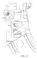
- FIG. 21 depicts a film processing step, wherein a strip of film exits a festoon box and proceeds to a scanner.
-
- The present invention is directed to photographic processors. An exemplary photographic processor of the present invention is shown in FIG. 1. The
photographic processor 10 comprises at least an outer housing, which includes afirst side wall 11, abase housing member 12, andsecond side wall 13. Thephotographic processor 10 includes a circular processing chamber 14 (also referred to herein as the "circular processing drum 14"), which may be used to expose a given strip or roll of film to one or more photoprocessing chemicals.Photographic processor 10 further includes a film-loading/unloading device 15 positioned above and cooperating withcircular processing drum 14. Achemical delivery system 16 is positioned for easy access by a user (i.e., for maintenance or replacement purposes) at a location nearside wall 13 andbase housing member 12.Photographic processor 10 also includes acircular dryer 17 in the form of, for example, a cylinder, for drying the processed film.Dryer 17 is concentrically and co-axially positioned around processingdrum 14. Once a given strip or roll of film is dried indryer 17, the film proceeds to a scanner 18', which may be positioned abovechemical delivery system 16 in a space bordered byside wall 13 and leftinterior wall 18 or any other convenient location. - FIG. 2 depicts a rear view of
photographic processor 10. As shown in FIG. 2,photographic processor 10 includes opening 19 inside wall 13 for accessingchemical delivery system 16.Sliding track mechanism 20 allows an operator to pull at least a portion ofchemical delivery system 16 through opening 19 to an exterior location outside ofphotographic processor 10. Such an assembly allows for quick and easy maintenance and replacement ofchemical delivery system 16.Photographic processor 10 can include a waste collection reservoir 21, which collects and stores used processing chemicals removed fromcircular processing drum 14 following development of a given strip or roll of film. As shown in FIG. 2,dryer 17 includesdryer entrance 171 anddryer blower 172. The various components ofphotographic processor 10 will be described in more detail below with reference to FIGS. 3-21. -
Circular processing drum 14 is further described in FIG. 3. As shown in FIG. 3,circular processing drum 14 includes afirst wall 141, asecond wall 142, aside wall 143, and a central axis opening 144. A portion of a drum and disk drive mechanism 25 (shown in FIGS. 2, 8 and 9) passes throughcentral access opening 144.Circular processing drum 14 comprises two circular sections joined together at multiple locations around the perimeter ofcircular processing drum 14 viamale clasping members 145 andfemale clasping members 146. It should be noted that any means for attaching the two circular components ofcircular processing drum 14 may be used in place ofmale clasping members 145 andfemale clasping members 146. Further, it should be noted thatcircular processing drum 14 may also consist of a single component as oppose to two circular components as shown in FIG. 3, although such a design may add manufacturing cost tocircular processing drum 14.Circular processing drum 14 further comprises a filmcartridge loading area 147 on an outer surface ofside wall 143 for loading film directly from a film cartridge intocircular processing drum 14, such as with APS film.Circular processing drum 14 also comprises afilm input slot 148, which enables the entry and exit of film intocircular processing drum 14. - FIG. 4 depicts an
exemplary disk 30, which is positioned withincircular processing drum 14, and functions to convey film withincircular processing drum 14 once the film enters throughfilm input slot 148.Disk 30 includes afirst face 31, asecond face 32, a central access opening 33, anouter perimeter 34, and one or more sets ofdisk teeth 35 located alongouter perimeter 34 ofdisk 30. As withcircular processing drum 14, a portion of drum anddisk drive mechanism 25 may extend into central access opening 33 to engage with and cause rotation ofdisk 30. FIG. 5 provides a close-up view of a portion ofdisk 30, and in particular,outer perimeter 34 and a set ofdisk teeth 35 on theouter perimeter 34 ofdisk 30. The outermost points ofdisk teeth 35 are in close proximity to an inner surface ofside wall 143 ofcircular processing drum 14. In a feature of the invention,disk teeth 35 could be spring loaded through the use ofsprings 35a. - In one feature of the present invention, a roller arrangement 27 (Figs. 6 and 7) is positioned within
circular processing drum 14.Roller arrangement 27 includes aroller 270 havinginterengaging members 277 and 278 (Fig. 7).Roller arrangement 27 may be supported by asupport member 28, which is attached to asupport member base 29.Support member base 29 may be permanently or temporarily attached to base housing member 12 (shown in FIGS. 1 and 2).Roller arrangement 27 includes amotor 271, which provides motion topistons 272 throughopenings 273 in a fixedpositioning member 274.Pistons 272 proceed through stationarypositioning support member 276 and are attached to movablepositioning support member 275. Aspistons 272 move, movablepositioning support member 275 which is coupled tomember 277 separates from stationarypositioning support member 276 which is coupled tomember 278. This permitsroller 270 to be expandible between a first width when themembers members - FIG. 7 provides a detailed view of
roller arrangement 27 and its various components. As shown in FIG. 7, movablepositioning support member 275 and stationarypositioning support member 276 connect tointerengaging members roller 270 and an interior surface ofdrum 14.Roller 270 is freely rotatable and maintains the film flat along the lower portion ofdrum 14. As will be described later,roller 270 further provides an agitating feature within processingdrum 14 during processing. Additionally, the width ofroller 270 is adjustable as described above to accommodate a shorter width film (i.e. APS film) and a larger width film (i.e. 35mm film). Further,roller arrangement 27 includingroller 270 can be vertically adjustable to accommodate for film curl as the film passes betweenroller 270 and the interior surface ofdrum 14. As a still further option,roller 270 can be spring loaded so as to accommodate any variation in the interior surface ofdrum 14. - In a further embodiment of the present invention,
circular processing drum 14 is connected to a drum anddisk drive mechanism 25, which selectively rotatesdisk 30 relative to drum 14 to position and convey the film along and withinprocessing drum 14, and rotates bothdisk 30 anddrum 14 together during a processing cycle.Circular processing drum 14 rotates about an axis of symmetry. An exemplary drum anddisk drive mechanism 25 is shown in FIG. 8. Drum anddisk drive mechanism 25 cooperates with amotor 22, abelt 23, and apulley 24 as shown in FIGS. 8 and 9A. Drum anddisk drive mechanism 25 includes adrive shaft 261 which is operationally connected topulley 24. Also shown in Figs. 8 and 9A areflanges Flange 251 is connected to drum 14 while anend cap 300 holdsdisk 30 for rotation about drive shaft 261 (Fig. 9A). Actuation ofmotor 22drives belt 23 which in turn drivespulley 24. This in turn causes a rotation ofdrive shaft 261 which rotatesdisk 30.Clutch mechanism 250 enables the engagement and disengagement offlange 251 to provide selective rotation tocircular processing drum 14. - FIG. 9A displays a cross-sectional view of drum and
disk drive mechanism 25 andclutch mechanism 250 alongline 9A-9A in FIG. 8. With reference to Fig. 9A and Fig. 9B which is a schematic representation of the driving and clutching feature of the present invention, an operation will now be described. When loading film which will be described with reference to Figs. 10 and 11,clutch 250 is deactivated as shown in Fig. 9B. In this state, rotation ofmotor 22 will cause a rotation ofdrive shaft 261 and accordingly, a rotation ofdisk 30 relative to drum 14. This is due to the fact thatclutch 250 is deactivated and therefore, drum 14 is not rotated. This permits the conveyance of the film by rotation ofdisk 30 to a desired location withindrum 14. After the film reaches the desired location withindrum 14,clutch 250 is activated, (for example, clutch 250 is moved to the right in Fig. 9B) by actuating clutch 250 withflange 251 which is attached to drum 14. Therefore, a rotation ofmotor 22 will cause a rotation of bothdisk 30 anddrum 14. This occurs during the processing stages to process the film in a manner which will be described later. - In a further feature of the invention,
drive shaft 261 can be moved perpendicularly and throughflange 251 andflange 252 to movedisk 30 attached thereto. As shown in Fig. 9A,drive shaft 261 is attached to a fitting 264 in a manner which permits driveshaft 261 to rotate relative to fitting 264. Fitting 264 is in turn rotatably attached to apivotable arm 262 and amovable member 263.Movable member 263 can be operationally connected to a motor for rotation ofmember 263. This causesarm 262 to pivot about point 262' to movedrive shaft 261 to the left or right when viewing Fig. 9A from above the page. Movement ofdrive shaft 261 as noted above, movesdisk 30 in a direction parallel to an axis ofdisk 30. This facilitates the accommodation of, for example, 35mm and APS film ondisk 30, since thedisk 30 can be moved based on the type of film being processed. - Within the context of the present invention, a film may be loaded into
circular processing drum 14 by a number of methods. One method of loading film, such as APS film, intocircular processing drum 14 is shown in FIGS. 10-13. As shown in FIG. 10,film cartridge 40 comprising afilm cartridge spool 41 and film cartridgedoor opening mechanism 52 is positioned in a filmcartridge loading area 147 located onside wall 143 ofcircular processing drum 14. Film (not shown) exitingfilm cartridge 40 enterscircular processing drum 14 at light tight film input slot 148 (Fig. 3) inside wall 143 ofcircular processing drum 14. - Once
film cartridge 40 is positioned in filmcartridge loading area 147, thephotographic processor 10 of the present invention initiates a number of film-loading and conveying steps, the results of which are shown in FIG. 11. It is noted that the film loading and conveying steps as well as other processing steps can be controlled by a computer or central processing unit 2000 (Fig. 1) operationally associated withprocessor 10. In a first step, a filmcartridge stabilizing member 50 applies an amount of pressure onto an upper surface offilm cartridge 40 to preventfilm cartridge 40 from moving while positioned in filmcartridge loading area 147.Spool engaging member 51 and cartridge door openingmechanism engaging member 52 move towardfilm cartridge 40 and engage withfilm cartridge spool 41 andfilm cartridge door 42, respectively. Door openingmechanism engaging member 52 opensfilm cartridge mechanism 42 andspool engaging member 51 begins to rotatefilm cartridge spool 41, forcing film (not shown) out offilm cartridge 40. - FIG. 12 shows a strip of
film 43 exitingfilm cartridge 40 and enteringfilm input slot 148 ofcircular processing drum 14. Driven niprollers 150 grasp a leading edge of the strip offilm 43 at drum roller nippoint 151 andadvance film 43 further intocircular processing drum 14. As shown in FIG. 13, the strip offilm 43 exits drumcavity slot 152 and enters into thedrum processing cavity 1521 ofcircular processing drum 14, wherein one or more sets ofdisk teeth 35 ondisk 30 interengage with holes or perforations along an edge of the strip offilm 43. As previously described,disk teeth 35 could be spring loaded so as to spring up at the appropriate time and interengage with the holes or perforations alongfilm 43. Withclutch 250 disengaged,disk 30 androllers 150 are rotated whilecircular processing drum 14 remains stationary. This causesfilm 43 to advance into theprocessing cavity 1521 of circular processing drum 14 a desired distance equal to the length of the strip or roll offilm 43. As shown in FIGS. 10-13, in this film-loading method of the present invention, thefilm 43 remains intact withfilm cartridge 40. - A number of commercially available films may be loaded according to the film-loading method described above, namely, wherein the film remains intact with its corresponding film cartridge during processing. A suitable film, which may be used in this particular film-loading method, includes, but is not limited to, APS film. Desirably, APS film is loaded into the photographic processor of the present invention according to this method.
- FIG. 14 depicts
circular processing drum 14 fully loaded withfilm 43 having aforward end 431 and arearward end 432 within thedrum processing cavity 1521 ofcircular processing drum 14. The back end offilm 43 is maintained incartridge 40.Film 43 is now positioned withincircular processing drum 14 for chemical processing, wherein one or more processing fluids are deposited intocircular processing drum 14 and placed in contact withfilm 43 for a desired period of time. - It is noted that the circumference of the drum will be longer than the length of the film to be processed. Therefore, when the film is loaded in
drum 14, a section ofdrum 14 will not have film therein. This is referred to as a film-free zone 431' (Fig. 14). Prior to delivering chemistry by way ofchemical supply 16 and a chemical delivery mechanism 16' (Fig. 14),clutch 250 is activated or engaged anddrum 14 is controllably rotated withdisk 30 so that film-free zone 431' is at a lower end or below chemical delivery mechanism 16'. Chemical delivery mechanism 16' is preferably of the type which drops or delivers chemistry intodrum 14 in the direction of arrow 1600 (Fig. 14). The movement of film-free zone to an area below chemical delivery mechanism 16' prior to the delivery of chemicals prevents the chemicals from being dropped directly on the film which could cause uneven processing. Thereafter, processing occurs by continuously rotating thedrum 14 anddisk 30. Further, as shown in Fig. 14, in the lower portion ofdrum 14,film 43 passes betweenwheel 270 and an inner surface ofdrum 14. Rotation ofdrum 14 anddisk 30 relative towheel 270 helps to agitate the processing fluid in the vicinity ofwheel 270 to promote processing. Following the chemical processing steps, thefilm 43 is removed fromcircular processing drum 14 and exposed to a drying operation. One method of removingfilm 43 fromcircular processing drum 14 is shown in FIGS. 15A and 15B. - As shown in FIG. 15A, film
transfer arm assembly 60 is positioned to move or pivot betweencircular processing drum 14 anddryer 17. Filmtransfer arm assembly 60 includes alower arm member 61, which is rotatable around an axis ofsymmetry 153 ofcircular processing drum 14. Filmtransfer arm assembly 60 also includes anupper arm member 62, which is pivotally attached tolower arm member 61. At upper arm member end 63, filmtransfer arm assembly 60 includes afilm cartridge gripper 64 and film strip gripper rolls 65. As shown in Fig. 15B, which is a front view of the entrance ofdryer 17, a side wall ofdryer 17 includes aslot 1700 with a rubber seal that extends along the length of the dryer.Upper arm member 62 includes ashaft 620 which extends fromupper arm member 62, throughslot 1700 and is connected togripper 64. This permitstransfer arm assembly 60 to pullgripper 64 and thus the film to be dried though the dryer. - In embodiments wherein the
film 43 remains intact with film cartridge 40 (as described above),film cartridge gripper 64 of filmtransfer arm assembly 60 engages withfilm cartridge 40, pullsfilm cartridge 40 fromloading area 147 and the strip offilm 43 fromcircular processing drum 14 indirection 600a, and proceeds throughdryer 17 indirection 600b. Therefore,cartridge 40 with processedfilm 43 attached and trailing therefrom is conveyed throughdryer 17 todry film 43 by, for example, the blowing of air intodryer 17. In other embodiments where thefilm 43 is detached from film cartridge 40 (described below), film sheet gripper rolls 65 grip an edge offilm 43 asfilm 43 exitsfilm input slot 148 ofcircular processing drum 14. Film sheet gripper rolls 65 of filmtransfer arm assembly 60pull film 43 fromcircular processing drum 14 and proceeds throughdryer 17. Once dried,film 43 is re-wound back into itscartridge 40 prior to proceeding to scanner 18'. - In a further film-loading method of the present invention, the film is separated from its film cartridge prior to processing within circular processing drum 14 (for example, 35mm film). In this method, a film loading/unloading device, such as exemplary film loading/
unloading device 15 as shown in FIG. 16, may be used. Film loading/unloading device 15 includes a filmcartridge loading area 154, which can be enclosed by closing adoor 158. Infilm loading area 154, an operator extracts the tongue of film 43' from cartridge 40' and engages the perforations on film 43' with sprockets on a drivenroller 1570. Thereafterdoor 158 is closed and film 43' proceeds intofestoon box 155 through festoon box niprollers 156. Once a desired length of film is removed from film cartridge 40', acutter 157 slices film 43' to separate film 43' from film cartridge 40'. Any counter device (not shown) may be used to measure the length of the strip of film 43' passing through festoon box niprollers 156. The length measurement is used in further processing steps as described below. - FIG. 17 depicts a cross-sectional view of film loading/
unloading device 15 as seen along line 17-17 in FIG. 16. As shown in FIG. 17, film cartridge 40' is positioned in filmcartridge loading area 154 while a strip of film 43' is removed from film cartridge 40' and transported to festoonbox 155 where it is turned. In this film-loading operation, a reverse roll offilm 431 is formed from the film 43' infestoon box 155. A lead end offilm 432 becomes the innermost portion of thereverse roll 431 while a tail end offilm 433 becomes the outermost portion of reversedroll 431. When the film 43' is subsequently fed into circular processing drum 14 (as previously described),tail end 433, which contains the last exposures on the strip of film 43', is fed intocircular processing drum 14 first. - A film-
loading guide 159 is used to loadreverse roll 431 intocircular processing drum 14 as shown in FIG. 18.Festoon box 155 rotates from an initial position (as shown in FIGS. 16 and 17) to a film-loading position as shown in FIG. 18. Festoon box niprollers 156 turn to advancetail end 433 ofreverse roll 431 into film-loading guide 159 atguide entrance slot 1591. The film 43' exits the film-loading guide 159 atguide exit slot 1592 positioned adjacent to filminput slot 148 ofcircular processing drum 14. Once thetail end 433 of the strip of film 43' enters intocircular processing drum 14, driven niprollers 150 grab the film 43' and advance the film 43' intocircular processing drum 14 as described above. It should be noted that in this film-loading method, niprollers 150 are programmed to advance the film 43' into circular processing drum 14 a specific length, which corresponds to the length of film inputted intofestoon box 155 and measured via festoon box niprollers 156 as described above. In other words, niprollers 150 advance the strip of film 43' intocircular processing drum 14 so thatlead end 432 of film 43' remains nipped between niprollers 150 during chemical processing (i.e.,lead end 432 of the strip of film 43' does not enter into drum processing cavity 1521). This permits all of the exposed areas of the film 43' to be in the processing area in the drum. - Following the chemical processing steps, film 43' is transferred to
dryer 17 by filmtransfer arm assembly 60 as described above. As shown in FIG. 19, the strip of film 43' is pulled fromcircular processing drum 14 throughfilm input slot 148 by film sheet gripper rolls 65 attached to uppertransfer arm member 62.Nip rollers 150 provide a first end (corresponding to lead end 432) to film sheet gripper rolls 65. In FIG. 19, film sheet gripper rolls 65 are shown positioned atdryer entrance 171. From this position, film sheet gripper rolls 65 proceed throughdryer 17 pulling the film 43' throughdryer 17. As shown in FIG. 20, upper filmtransfer arm member 62exits dryer 17 atdryer exit 173 and comes into contact with aconduit 70. Film sheet gripper rolls 65 turn to advance the film 43' throughconduit 70 and intoscanner festoon box 71. Scanner festoon box niprollers 72 grasp a leading edge of film 43' and force film 43' intoscanner festoon box 71 formingscanner film roll 435. Scanner festoon box niprollers 72 advance film 43' into scanner festoon box 71 a specific distance equal to the predetermined length of film 43' so that the tail end of film 43' remains nipped between scanner festoon box niprollers 72 to go to the scanner. - In one embodiment of the present invention, film 43' may be further processed by transporting the film 43' to scanner 18'. As shown in FIG. 21,
scanner festoon box 71 rotates from an initial position (as shown in FIG. 20) to a secondary position so that the film 43' may be fed to scanner 18'. Scanner 18' may supply image data tocomputer 2000 or a remote computer (not shown) for further image processing. Following scanning, the film 43' may be packaged as a film roll or as strips of film and returned to the customer along with scanned photographs in electronic format on an electronic disc if desired. - A number of commercially available films may be loaded according to the film-loading method described above, namely, wherein the film is separated from its corresponding film cartridge during processing. Suitable films, which may be used in this particular film-loading method, include, but are not limited to, 135 mm film. Desirably, 135 mm film is loaded into the photographic processor of the present invention according to this method.
- The photographic processor of the present invention may be used to process one or more types of film. Suitable films include, but are not limited to, APS film, 135 mm film, etc. Desirably, the photographic processor of the present invention is designed to process APS film, 135 mm film, or both APS and 135 mm film. The photographic processor of the present invention may be categorized as a "single-roll" processing unit given that the circular processing drum only processes one roll of film at a time. However, it should be noted that the photographic processor of the present invention is capable of processing multiple rolls of film at a given time. For example, one roll of film may be in the circular processing drum, while a second roll of film is in the dryer and a third roll of film is in the scanner.
- The photographic processor of the present invention may include other components other than those described in FIGS. 1-21. For example, the photographic processor of the present invention may include an operator interface control panel operationally associated with computer 2000 (Fig. 1); a display screen; a control unit, wherein the control unit accepts input from a processor user, provides machine settings to one or more components of the processor based on the input of the user, and controls and executes a processing operation of the processor; and multiple film loading doors on an outer surface of the photographic processor housing. In one desired embodiment of the present invention, the photographic processor is used to process APS film and 135 mm film. In this embodiment, the photographic processor has two separate film loading doors on an outer surface of the photographic processor housing, one for an APS film cartridge and the other for a 135 mm film cartridge.
- The photographic processor of the present invention may come in a variety of sizes depending on a number of factors including, but not limited to, the desired size of the circular processing drum, the desired storage capacity of the chemical delivery system, and the desired storage capacity of the waste collection reservoir. One of the benefits of the photographic processor of the present invention is the ability to place the photographic processor in a given room without occupying a large amount of space.
- Another benefit of the photographic processor of the present invention is that the only requirement necessary to operate the photographic processor in a given room is a source of electricity. Since the photographic processor of the present invention can operate with working strength chemistry, the processor does not require a water source or drain for processing chemicals. A minimum amount of processing chemicals is needed to operate the photographic processor of the present invention due to the unique design of the circular processing drum. Further, a minimum amount of chemical waste is generated due to the design of the circular processing drum.
- The circular processing drum of the photographic processor may vary in size depending on a number of factors including, but not limited to, the type of film processed, the length of the film processed, the width of the film processed, and the desired overall dimensions of the photographic processor. In one embodiment of the present invention, the length of the drum (i.e., the dimension perpendicular to the diameter of the drum) is substantially equal to the sum of (1) a thickness of the front wall of the drum, (2) a thickness of the back wall of the drum, and (3) a width of the strip of processible film. In a further embodiment of the present invention, the drum has a circumference, which is slightly greater than largest length of the roll film.
- In one embodiment of the present invention, the photographic processor comprises (1) a circular processing drum having a front wall, a back wall, a side wall connecting the front wall to the back wall and extending around a perimeter of the drum, and a horizontally extending axis of symmetry, wherein the diameter of the drum is greater than a length of the drum, which is measured along the axis of symmetry; (2) a disk positioned inside the drum in a plane parallel to both the front wall and the back wall, wherein the disk comprises one or more sets of disk teeth along an outer perimeter of the disk capable of interengaging with holes along a first edge of a sheet of processible film; and (3) a mechanism for rotating the disk while the drum is stationary. The mechanism for rotating the disk may be capable of rotating the disk and the drum simultaneously, or selectively rotating only the disk. The mechanism for rotating the disk may comprise a number of components including, but not limited to, a motor, a clutch, and a drive axis, wherein the drive axis is positioned along the axis of symmetry of the drum.
- The circular processing drum and/or the disk may be rotated at a speed depending on a number of factors including, but not limited to, the type of film, the size of the circular processing drum, the desired amount of contact time between each of the one or more processing solutions and the roll of film, and the desired speed at which film is introduced into the circular processing drum.
- In a further embodiment of the present invention, the photographic processor comprises a circular processing drum, wherein the circular processing drum comprises a disk having one or more sets of teeth. The one or more sets of teeth interengage with holes along the film to pull the film into the circular processing drum.
- The photographic processor of the present invention may use any conventional chemical delivery system known in the art as long as the chemical delivery system is capable of inputting one or more processing fluids into the circular processing drum. Suitable chemical delivery systems deliver one or more processing fluids including, but not limited to, a developing solution, a bleach solution, a fix solution, a wash solution, or a combination thereof. Desirably, the chemical delivery system comprises one or more separate containers for each of the processing fluids. For example, the chemical delivery system may comprise one or more separate containers containing a developing solution, one or more separate containers containing a bleach solution, one or more separate containers containing a fix solution, and one or more separate containers containing a wash solution. In one embodiment of the present invention, the chemical delivery system used in the photographic processor comprises one container of developing solution, one container of bleach solution, one container of fix solution, and at least one container of wash solution.
- Desirably, the photographic processor of the present invention utilizes a chemical delivery system comprising "working strength" chemical solutions. As used herein, the term "working strength" is used to describe chemical solutions, which are prepackaged in separate containers at concentrations that do not require dilution with other solutions (i.e., a source of water), and can be used as is.
- Further, the photographic processor of the present invention may use any conventional chemical removal system to remove one or more processing fluids from the circular processing drum. Suitable chemical removal systems include, but are not limited to, a suction device or a drain 3000 (Fig. 14) in the side wall of the circular processing drum. Typically, the chemical removal system further comprises a chemical waste reservoir 3002 (Fig. 14) for storing one or more processing fluids removed from the drum. Desirably, the chemical waste reservoir is designed to contain all of the waste resulting from the use of all of the processing fluids contained in the chemical delivery system.
- As discussed above, the photographic processor of the present invention uses a minimum amount of photoprocessing chemicals, and consequently generates a minimum amount of chemical waste.
- The dryer of the invention should be capable of drying the processed film. The dryer may use air and/or radiant heat to dry the processed film. Desirably, the dryer has a capacity, which minimizes the amount of dwell time within the dryer. Also, it is preferable that the dryer be compact and positioned next to the circular processing drum as shown in FIGS. 1-2 above.
- The photographic processor of the present invention may include a film-loading device, wherein the film loading device comprises one or more of the following components: (a) a film cartridge stabilizing bar for fixing a position of a film cartridge in a film cartridge loading area on an outer surface of the side wall; (b) a film cartridge door opening device; (c) a film cartridge spool turning device; (d) a festoon box for storing film removed from a film cartridge; (e) a cutting device for cutting film to separate the film from a film cartridge; and (f) a festoon box nip rollers for gripping film. Desirably, the film-loading device comprises all of the above components.
- In a further desired embodiment of the present invention, the photographic processor comprises (1) a circular processing drum having a front wall, a back wall, a side wall connecting the front wall to the back wall and extending around a perimeter of the drum, and a horizontally extending axis of symmetry, wherein the diameter of the drum is greater than a length of the drum, which is measured along the axis of symmetry of the drum; (2) a disk positioned inside the drum in a plane parallel to both the front wall and the back wall, wherein the disk comprises one or more sets of disk teeth along an outer perimeter of the disk capable of interengaging with holes along a an edge of a strip of processible film; and (3) a disk positioning device, wherein the disk positioning device moves the disk within the drum to change a distance between the disk and the front wall of the drum. The photographic processor may further comprise a mechanism (a) for rotating the disk and the drum simultaneously, and (b) for rotating the disk while the drum is stationary.
- The present invention is further directed to a photographic process, wherein the process comprises the steps of: (1) loading a sheet of processible film into a circular processing drum, wherein the circular processing drum comprises (a) a front wall, (b) a back wall, (c) a side wall connecting the front wall to the back wall and extending around a perimeter of the drum, and (d) a horizontally extending axis of symmetry, wherein the drum has a diameter greater than a length of the drum, the length of the drum being measured along the axis of symmetry of the drum, and wherein the drum contains a disk positioned inside the drum in a plane parallel to both the front wall and the back wall, wherein the disk comprises one or more sets of disk teeth along an outer perimeter of the disk capable of interengaging with holes along a first edge of the sheet of processible film; (2) contacting the sheet of processible film with one or more processing fluids in the circular processing drum; (3) rotating the circular processing drum along the axis of symmetry for a period of time; (4) removing the one or more processing fluids from the circular processing drum; and (5) drying the film. In the above method, the loading step may comprise one or more of the following steps: (i) feeding the sheet of processible film into the circular processing drum through a film-loading slot in the side wall of the drum; (ii) nipping the sheet of processible film to move the sheet of processible film into contact with the one or more sets of disk teeth along the disk; and (iii) rotating the disk while the drum remains stationary to advance the sheet of processible film into the circular processing drum.
- The photographic process of the present invention may comprise contacting a strip of film with one or more processing fluids selected from a developing solution, a bleach solution, a fix solution, a wash solution, or a combination thereof. In one embodiment, the photographic process comprises a contacting step, which comprises (i) inputting a developing solution into the circular processing drum; (ii) inputting a bleach solution into the circular processing drum; (iii) inputting a fix solution into the circular processing drum; and (iv) inputting at least one wash solution into the circular processing drum. The contacting step of the process may further comprise separate removal steps following a washing solution input step. As an alternative, the process may comprise inputting a developing solution into the drum; inputting a fix solution into the drum; inputting a bleach solution into the drum; and inputting at least one wash solution into the drum.
- The photographic process of the present invention may further comprise a rotating step, wherein the rotating step comprises rotating the drum and the disk simultaneously. The drum and the disk may be simultaneously rotated after each processing solution input step for a period of time in order to insure a desired amount of contact between each processing solution and the film.
- The photographic process of the present invention may comprise a series of processing steps, wherein the film remains intact with its corresponding film cartridge (for example, APS film). In other embodiments, the photographic process of the present invention comprises removing the processible film from a film cartridge (i.e. 35 mm film), and cutting the processible film to separate the processible film from the film cartridge When the film is to remain intact with its film cartridge (i.e. APS film), the photographic process of the present invention may comprise one or more of the following film loading steps: (a) positioning a film cartridge containing the strip of processible film in a film cartridge loading area on an outer surface of the side wall; (b) applying a film cartridge stabilizing bar to an upper surface of the film cartridge to secure the film cartridge; (c) opening a door of the film cartridge; and (d) turning a spool within the film cartridge. When the film is to be separated from its film cartridge (i.e. 35 mm film), the photographic process of the present invention may comprise one or more of the following film loading steps: (a) positioning a film cartridge containing the strip of processible film in a film cartridge loading area adjacent to a festoon box; (b) pulling a tongue on the film from the film cartridge using, for example, a film extraction tool; (c) engaging perforations on the film on a sprocket wheel; (d) transferring the film from the film cartridge to the festoon box to form a roll of film; wherein a last exposure on the film is on an outer portion of the roll of film; and (e) cutting the film to separate the film from the film cartridge.
- In a further embodiment, the present invention is directed to a photographic process which comprises moving a disk within a circular processing drum along an axis of symmetry of the drum to change a distance between the disk and a wall, such as the front wall, of the drum. In this embodiment, the photographic process is capable of processing different types of film using the same circular processing drum by adjusting the position of the disk within the circular processing drum.
- While the specification has been described in detail with respect to specific embodiments thereof, it will be appreciated that those skilled in the art, upon attaining an understanding of the foregoing, may readily conceive of alterations to, variations of, and equivalents to these embodiments. Accordingly, the scope of the present invention should be assessed as that of the appended claims and any equivalents thereto.
Claims (10)
- A photographic processor comprising:a circular processing drum (14) having a front wall, a back wall, a side wall connecting the front wall to the back wall and extending around a perimeter of the drum, and a horizontally extending axis of symmetry, wherein a diameter of the drum is greater than a length of the drum, wherein the length of the drum is measured along the axis of symmetry;a disk (30) positioned inside the drum in a plane parallel to both the front wall and the back wall, wherein the disk (30) comprises one or more sets of disk teeth along an outer perimeter of the disk capable of interengaging with holes along a first edge of a strip of processible film; anda mechanism (25) for rotating the disk while the drum is stationary.
- The photographic processor of Claim 1, wherein the mechanism is capable of rotating the disk and the drum simultaneously.
- The photographic processor of Claim 1, further comprising a film-loading slot (148) in the side wall of the drum.
- The photographic processor of Claim 1, further comprising a disk positioning device (262, 263), wherein the disk positioning device moves the disk within the drum to change a distance between the disk and the front wall of the drum.
- The photographic processor of Claim 1, further comprising a circular dryer (17) for drying the film, said dryer extending around an outer perimeter of the drum.
- The photographic processor of Claim 1, further comprising a gripper (64), wherein the gripper removes film from the drum and transfers the film to the dryer.
- A photographic processor comprising:a circular processing drum (14) having a front wall, a back wall, a side wall connecting the front wall to the back wall and extending around a perimeter of the drum, and a horizontally extending axis of symmetry, wherein the diameter of the drum is greater than a length of the drum, wherein the length of the drum is measured along the axis of symmetry;a disk (30) positioned inside the drum in a plane parallel to both the front wall and the back wall, wherein the disk comprises one or more sets of disk teeth along an outer perimeter of the disk capable of interengaging with holes along an edge of a strip of processible film; anda disk positioning device (262, 263), wherein the disk positioning device moves the disk within the drum to change a distance between the disk and the front wall of the drum.
- A photographic process comprising:loading processible film into a circular processing drum, wherein the circular processing drum comprises:a front wall,a back wall,a side wall connecting the front wall to the back wall and extending around a perimeter of the drum, anda horizontally extending axis of symmetry, and wherein the drum has a diameter greater than a length of the drum, the length of the drum being measured along the axis of symmetry, and wherein the drum contains a disk positioned inside the drum in a plane parallel to both the front wall and the back wall, wherein the disk comprises one or more sets of disk teeth along an outer perimeter of the disk capable of interengaging with holes along a an edge of the strip of processible film;contacting the processible film with one or more processing fluids in the circular processing drum;rotating the circular processing drum along the axis of symmetry for a period of time to process the film;removing the one or more processing fluids from the circular processing drum; anddrying the processed film.
- A method of processing a photosensitive film comprising the steps of:inserting the film into a circular processing drum;supplying and discharging processing solution into and from said processing drum to process said film;transferring the processed film from the circular processing drum to a circular drying cylinder; anddrying the processed film as the film travels through the circular drying cylinder.
- A processing apparatus comprising:a circular processing drum (14) for processing a photosensitive film therein;a circular drying cylinder (17) for drying the processed photosensitive film; anda transfer arm (60) for transferring the processed photosensitive film from the processing drum to the drying cylinder.
Applications Claiming Priority (2)
| Application Number | Priority Date | Filing Date | Title |
|---|---|---|---|
| US27382 | 2001-12-21 | ||
| US10/027,382 US6485202B1 (en) | 2001-12-21 | 2001-12-21 | Photographic processor and method of operation |
Publications (1)
| Publication Number | Publication Date |
|---|---|
| EP1321819A1 true EP1321819A1 (en) | 2003-06-25 |
Family
ID=21837411
Family Applications (1)
| Application Number | Title | Priority Date | Filing Date |
|---|---|---|---|
| EP02080087A Withdrawn EP1321819A1 (en) | 2001-12-21 | 2002-12-09 | Photographic processing apparatus and method |
Country Status (3)
| Country | Link |
|---|---|
| US (1) | US6485202B1 (en) |
| EP (1) | EP1321819A1 (en) |
| JP (1) | JP2003195465A (en) |
Families Citing this family (2)
| Publication number | Priority date | Publication date | Assignee | Title |
|---|---|---|---|---|
| US6619862B1 (en) * | 2002-06-28 | 2003-09-16 | Eastman Kodak Company | Thermal management drum for a photographic processor |
| US6835010B1 (en) | 2003-10-18 | 2004-12-28 | Eastman Kodak Company | Outside load drum processor |
Citations (4)
| Publication number | Priority date | Publication date | Assignee | Title |
|---|---|---|---|---|
| US2413779A (en) * | 1944-01-28 | 1947-01-07 | Kraft Foods Co | Apparatus for stripping film from a drying cylinder |
| US3246400A (en) * | 1962-06-25 | 1966-04-19 | Bell & Howell Co | Drying drum |
| US4005463A (en) * | 1975-07-08 | 1977-01-25 | Charles Beseler Company | Photographic processing drum and method for using |
| DE19908917A1 (en) * | 1999-03-02 | 2000-09-07 | Schlafhorst & Co W | Drive disk for the carrier belt to remove dirt/debris from a textile machine has a peripheral groove to take a friction cladding as teeth with a toothed belt to prevent belt slippage |
Family Cites Families (4)
| Publication number | Priority date | Publication date | Assignee | Title |
|---|---|---|---|---|
| US3792651A (en) * | 1972-02-29 | 1974-02-19 | D Banks | Photographic processing apparatus |
| US4178088A (en) * | 1978-07-03 | 1979-12-11 | Harding Herbert D | Photographic processor |
| US4269501A (en) * | 1979-09-12 | 1981-05-26 | Griffith Glen A | Drum for an automatic photographic processing system |
| US4431294A (en) * | 1982-10-05 | 1984-02-14 | Pako Corporation | Rotation failure sensor for film disc processor |
-
2001
- 2001-12-21 US US10/027,382 patent/US6485202B1/en not_active Expired - Fee Related
-
2002
- 2002-12-09 EP EP02080087A patent/EP1321819A1/en not_active Withdrawn
- 2002-12-19 JP JP2002368589A patent/JP2003195465A/en active Pending
Patent Citations (4)
| Publication number | Priority date | Publication date | Assignee | Title |
|---|---|---|---|---|
| US2413779A (en) * | 1944-01-28 | 1947-01-07 | Kraft Foods Co | Apparatus for stripping film from a drying cylinder |
| US3246400A (en) * | 1962-06-25 | 1966-04-19 | Bell & Howell Co | Drying drum |
| US4005463A (en) * | 1975-07-08 | 1977-01-25 | Charles Beseler Company | Photographic processing drum and method for using |
| DE19908917A1 (en) * | 1999-03-02 | 2000-09-07 | Schlafhorst & Co W | Drive disk for the carrier belt to remove dirt/debris from a textile machine has a peripheral groove to take a friction cladding as teeth with a toothed belt to prevent belt slippage |
Also Published As
| Publication number | Publication date |
|---|---|
| JP2003195465A (en) | 2003-07-09 |
| US6485202B1 (en) | 2002-11-26 |
Similar Documents
| Publication | Publication Date | Title |
|---|---|---|
| US4837601A (en) | Automatic photographic paper processing apparatus | |
| US6485202B1 (en) | Photographic processor and method of operation | |
| US6485204B1 (en) | Photographic processor having an adjustable drum | |
| US6517263B1 (en) | Photographic processor having side by side processing paths and method of operation | |
| US6698946B1 (en) | Dual groove photographic processing drum | |
| US6722797B1 (en) | Photographic processing drum having a circular media holding cylinder and a linear dryer | |
| US6715942B1 (en) | Photographic processing drum having a circular drying cylinder | |
| US6729779B2 (en) | Photographic processing drum having a metering blade assembly | |
| US6896425B2 (en) | Queuing arrangement for photographic media to be scanned | |
| US6722799B1 (en) | Photographic processing drum having a centrally located processing solution delivery system | |
| US6595705B1 (en) | Photographic processor having a washing assembly | |
| US6599037B1 (en) | Ultrasonic cleaning in batch photoprocessing equipment | |
| JPS61292642A (en) | Photograph printing developing device | |
| JPH0738911Y2 (en) | Negative film stock device for automatic development and printing of photographic light-sensitive materials | |
| US5897070A (en) | Automatic film unloading apparatus and intermediate film takeup cartridge of automatic film developing apparatus | |
| US6619862B1 (en) | Thermal management drum for a photographic processor | |
| US6835010B1 (en) | Outside load drum processor | |
| US6802658B1 (en) | Transfer assembly and a dryer operationally associated with the transfer assembly | |
| US6719465B2 (en) | Rotating processor | |
| JP2935184B1 (en) | Conveying means of photo printing equipment | |
| JPS61203439A (en) | Automatic photographic printing device | |
| JPH07114108A (en) | Carrying device for photosensitive material | |
| JPS63200140A (en) | Photographic printer | |
| JPH01193827A (en) | Photograph producing device | |
| JPH0572704A (en) | Photograph producing device |
Legal Events
| Date | Code | Title | Description |
|---|---|---|---|
| PUAI | Public reference made under article 153(3) epc to a published international application that has entered the european phase |
Free format text: ORIGINAL CODE: 0009012 |
|
| AK | Designated contracting states |
Designated state(s): AT BE BG CH CY CZ DE DK EE ES FI FR GB GR IE IT LI LU MC NL PT SE SI SK TR |
|
| AX | Request for extension of the european patent |
Extension state: AL LT LV MK RO |
|
| 17P | Request for examination filed |
Effective date: 20031127 |
|
| AKX | Designation fees paid |
Designated state(s): DE FR GB |
|
| STAA | Information on the status of an ep patent application or granted ep patent |
Free format text: STATUS: THE APPLICATION HAS BEEN WITHDRAWN |
|
| 18W | Application withdrawn |
Effective date: 20050910 |