EP1321781A2 - Self-formable optical waveguide material composition - Google Patents
Self-formable optical waveguide material composition Download PDFInfo
- Publication number
- EP1321781A2 EP1321781A2 EP02027708A EP02027708A EP1321781A2 EP 1321781 A2 EP1321781 A2 EP 1321781A2 EP 02027708 A EP02027708 A EP 02027708A EP 02027708 A EP02027708 A EP 02027708A EP 1321781 A2 EP1321781 A2 EP 1321781A2
- Authority
- EP
- European Patent Office
- Prior art keywords
- photo
- curable resin
- refractive
- index
- optical waveguide
- Prior art date
- Legal status (The legal status is an assumption and is not a legal conclusion. Google has not performed a legal analysis and makes no representation as to the accuracy of the status listed.)
- Granted
Links
Images



Classifications
-
- G—PHYSICS
- G02—OPTICS
- G02B—OPTICAL ELEMENTS, SYSTEMS OR APPARATUS
- G02B6/00—Light guides; Structural details of arrangements comprising light guides and other optical elements, e.g. couplings
- G02B6/10—Light guides; Structural details of arrangements comprising light guides and other optical elements, e.g. couplings of the optical waveguide type
- G02B6/12—Light guides; Structural details of arrangements comprising light guides and other optical elements, e.g. couplings of the optical waveguide type of the integrated circuit kind
- G02B6/13—Integrated optical circuits characterised by the manufacturing method
-
- G—PHYSICS
- G02—OPTICS
- G02B—OPTICAL ELEMENTS, SYSTEMS OR APPARATUS
- G02B1/00—Optical elements characterised by the material of which they are made; Optical coatings for optical elements
- G02B1/04—Optical elements characterised by the material of which they are made; Optical coatings for optical elements made of organic materials, e.g. plastics
- G02B1/045—Light guides
- G02B1/046—Light guides characterised by the core material
-
- G—PHYSICS
- G02—OPTICS
- G02B—OPTICAL ELEMENTS, SYSTEMS OR APPARATUS
- G02B1/00—Optical elements characterised by the material of which they are made; Optical coatings for optical elements
- G02B1/04—Optical elements characterised by the material of which they are made; Optical coatings for optical elements made of organic materials, e.g. plastics
- G02B1/045—Light guides
- G02B1/048—Light guides characterised by the cladding material
-
- G—PHYSICS
- G02—OPTICS
- G02B—OPTICAL ELEMENTS, SYSTEMS OR APPARATUS
- G02B6/00—Light guides; Structural details of arrangements comprising light guides and other optical elements, e.g. couplings
- G02B6/10—Light guides; Structural details of arrangements comprising light guides and other optical elements, e.g. couplings of the optical waveguide type
- G02B6/12—Light guides; Structural details of arrangements comprising light guides and other optical elements, e.g. couplings of the optical waveguide type of the integrated circuit kind
- G02B6/122—Basic optical elements, e.g. light-guiding paths
- G02B6/1221—Basic optical elements, e.g. light-guiding paths made from organic materials
-
- G—PHYSICS
- G02—OPTICS
- G02B—OPTICAL ELEMENTS, SYSTEMS OR APPARATUS
- G02B6/00—Light guides; Structural details of arrangements comprising light guides and other optical elements, e.g. couplings
- G02B6/10—Light guides; Structural details of arrangements comprising light guides and other optical elements, e.g. couplings of the optical waveguide type
- G02B6/12—Light guides; Structural details of arrangements comprising light guides and other optical elements, e.g. couplings of the optical waveguide type of the integrated circuit kind
- G02B2006/12035—Materials
- G02B2006/12069—Organic material
Definitions
- the present invention relates to a self-formable optical waveguide material composition containing two photo-curable resins which have different refractive indices and which can be cured by different wavelengths respectively.
- photo-curable resin used in the invention means a monomer, a macro-monomer or an oligomer containing a photo-reaction initiator.
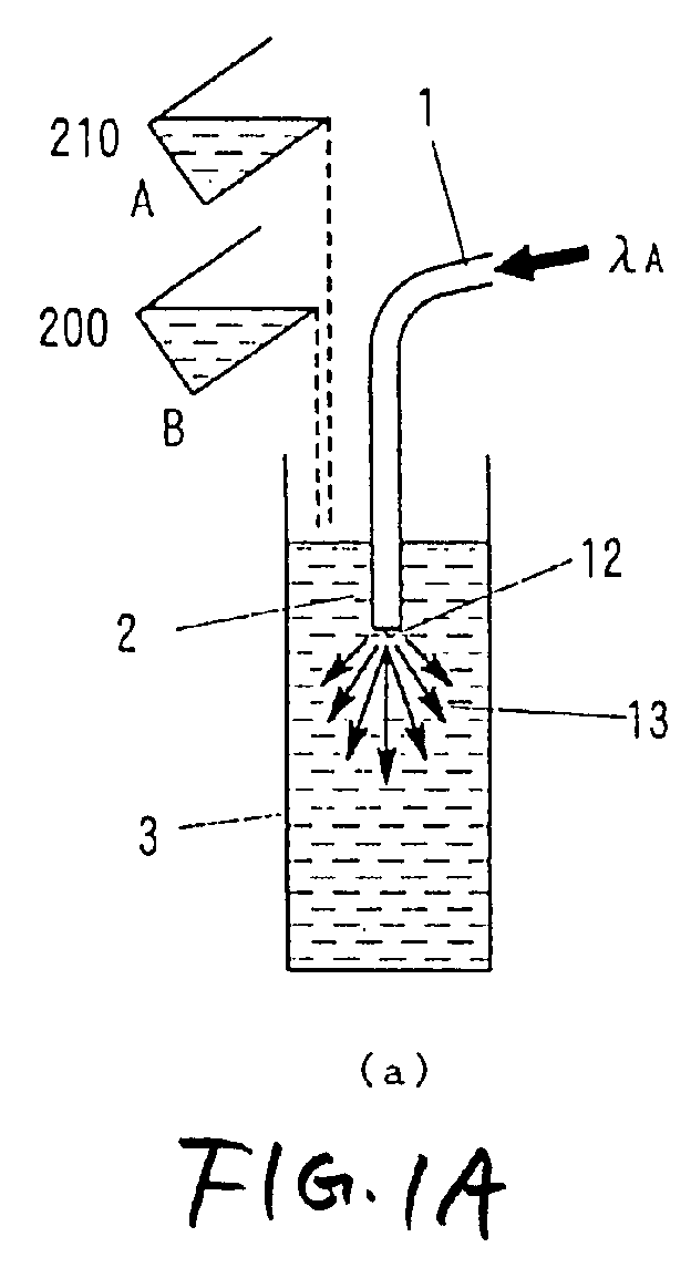
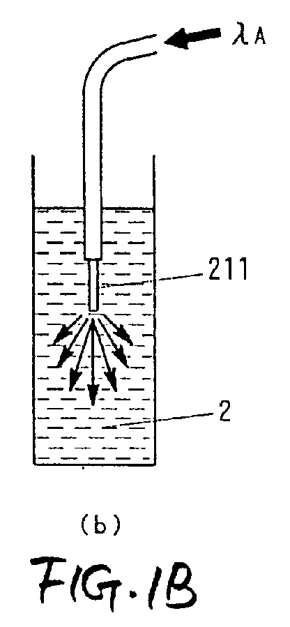
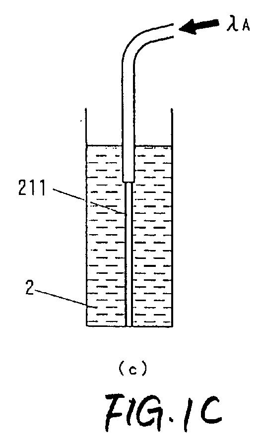
- the technique is as follows. Into a mixture solution containing a high-refractive-index photo-curable resin and a low-refractive-index photo-curable resin, light to cure only the high-refractive-index photo-curable resin is led through an optical fiber so that a high-refractive-index cured resin having a diameter substantially equal to the diameter of a core portion of the optical fiber is formed in the mixture solution so as extend from a tip of the optical fiber. Then, the residual mixture solution is cured, so that a module having the previously formed high-refractive-index resin as an optical waveguide can be formed easily.
- both the high-refractive-index photo-curable resin A and the low-refractive-index photo-curable resin B in a mixed state are cured by light at the wavelength ⁇ B given from the outside.
- a cured resin 23 which is not a copolymer but has a refractive index between refractive indices of two cured resins which can be obtained when the high-refractive-index photo-curable resin A and the low-refractive-index photo-curable resin B are cured singly respectively.
- the cylindrical cured resin 211 having a high refractive index and the cured resin 23 having a refractive index lower than that of the cylindrical cured resin 211 can form an optical waveguide (Fig. 1D).
- the inventors found that the mixed state of the high-refractive-index photo-curable resin A and the low-refractive-index photo-curable resin B before curing is very important. That is, in the optical waveguide constituted by the cylindrical cured resin 211 having a high refractive index and the cured resin 23 having a refractive index lower than that of the cylindrical cured resin 211, leakage loss can be reduced as the refractive index difference between the two cured resins 211 and 23 increases. This means the fact that the high-refractive-index photo-curable resin A and the low-refractive-index photo-curable resin B before curing are largely different from each other in terms of chemical structure.
- the mixed state is apt to become poor to cause a phenomenon that the mixture solution 2 turns white turbidly.
- optical waveguide-forming light in a photo-polymerization reactive portion is scattered to make the formation of the cylindrical cured resin 211 so insufficient that the cylindrical cured resin 211 can little grow occasionally.
- the amount of the high-refractive-index photo-curable resin A is extremely smaller than the amount of the low-refractive-index photo-curable resin B, the cylindrical cured resin 211 still little grows.
- an object of the invention is to find an appropriate combination of a high-refractive-index photo-curable resin A and a low-refractive-index photo-curable resin B by estimating solubility parameters of the two photo-curable resins A and B before curing.
- Another object of the invention is to find an appropriate composition on the basis of the relation in solubility parameter and volume fraction between a high-refractive-index photo-curable resin A and a low-refractive-index photo-curable resin B before curing.
- a self-formable optical waveguide material composition containing a first photo-curable resin which can be cured by a certain wavelength, and a second photo-curable resin which is not cured by the certain wavelength but can be cured by another wavelength, wherein the self-formable optical waveguide material composition satisfies the expression (1): ⁇ A - ⁇ B ⁇ 6.0 in which ⁇ A is a solubility parameter of the first photo-curable resin expressed in MPa 1/2 , and ⁇ B is a solubility parameter of the second photo-curable resin expressed in MPa 1/2 .
- the self-formable optical waveguide material composition satisfies the expression (2) or (3): ⁇ A - ⁇ B ⁇ 5.0 ⁇ A - ⁇ B ⁇ 4.0
- the ratio of the refractive index of the first photo-curable resin before curing to the refractive index of the second photo-curable resin before curing is higher than 1 but not higher than 1.14, and the volume fraction of the second photo-curable resin is not lower than 0.01 but lower than 0.8.
- this hereinafter means the fact that the refractive index of the first photo-curable resin before curing is not higher than 1.14 times as high as the refractive index of the second photo-curable resin before curing.
- the volume fraction of the second photo-curable resin means the ratio of the volume of the second photo-curable resin to the sum of the volume of the first photo-curable resin and the volume of the second photo-curable resin before mixing. Especially preferably, the volume fraction is selected to be not lower than 0.1.
- a self-formable optical waveguide material composition containing a first photo-curable resin which can be cured by a certain wavelength, and a second photo-curable resin which is not cured by the certain wavelength but can be cured by another wavelength, wherein: the ratio of the refractive index of the first photo-curable resin before curing to the refractive index of the second photo-curable resin before curing is higher than 1 but not higher than 1.14; and the self-formable optical waveguide material composition satisfies the expression (4): ⁇ A - ⁇ B ⁇ -7.5 ⁇ B + 6.0 in which ⁇ A is a solubility parameter of the first photo-curable resin expressed in MPa 1/2 , ⁇ B is a solubility parameter of the second photo-curable resin expressed in MPa 1/2 , and ⁇ B ( ⁇ B ⁇ 0.01) is a volume fraction of the second photo-curable resin. Especially preferably, the volume fraction ⁇ B is selected to be not
- the self-formable optical waveguide material composition satisfies the expression (5) or (6): ⁇ A - ⁇ B ⁇ -7.5 ⁇ B + 5.0 ⁇ A - ⁇ B ⁇ -7.5 ⁇ B + 4.0
- the inventors have found that the relation between the solubility parameter of the first photo-curable resin and the solubility parameter of the second photo-curable resin plays an important role in this subject of matter as will be described in the following embodiments. That is, it has been found that there is a large difference in optical waveguide-forming speed between the case where the restrictive item of each aspect of the invention is satisfied and the case where the restrictive item is not satisfied. This means the fact that it is important to provide a combination of the first photo-curable resin and the second photo-curable resin easily soluble in each other. That is, the condition that the two photo-curable resins are mixed well is essential for curing only the first photo-curable resin. The relation between the mixed state and the volume fraction, that is, the mixture ratio is more remarkable.
- the curing speed of the high-refractive-index photo-curable resin A to form a core of an optical waveguide was observed in the condition that the volume fraction of the high-refractive-index photo-curable resin A was 0.8. That is, in a reaction system shown in Figs. 1A to 1D, the length of the cured resin 211 obtained by irradiation with light for a predetermined time was measured.
- the solvent was not equivalent to the low-refractive-index photo-curable resin B but was used as a material substituted for the low-refractive-index photo-curable resin B for the sake of convenience in order to verify materials having various solubility parameters.
- An optical fiber 1 having a core diameter of 730 ⁇ m, a clad diameter of 750 ⁇ m and a numerical aperture of 0.25 was used. Monochromatic light at a wavelength of 488 nm was used as incident light. Results of the measurement were as shown in Fig. 2. In Fig. 2, the vertical axis was taken to express the relative length of the cured resin 211 whereas the horizontal axis was taken to express the absolute value of solubility parameter difference. The relative length was calculated as follows.
- the cured resin serving as a core of an optical waveguide was not formed at all if the absolute value of solubility parameter difference was larger than 6.0.
- the relative length of the cured resin serving as a core of an optical waveguide became noticeably large if the absolute value of the solubility parameter difference between the high-refractive-index photo-curable resin A and the low-refractive-index photo-curable resin B or solvent mixed therewith was not larger than 5.0.
- the relative length of the cured resin serving as a core of an optical waveguide became further larger if the absolute value of solubility parameter difference was not larger than 4.0.
- the vertical axis was taken to express the relative length of the cured resin 211 whereas the horizontal axis was taken to express the compounding ratio (volume fraction) of the low-refractive-index photo-curable resin B.
- the relative length was calculated as follows. Four low-refractive-index photo-curable resins B were one by one combined with a high-refractive-index photo-curable resin A to thereby form four combinations. While the compounding ratio (volume fraction) of each of the four combinations was changed, the length (mm) of the cured resin 211 was measured and divided by 20. The resulting value was obtained as the relative length of the cured resin 211. In any case, only a very short cured resin 211 was formed when the volume fraction ⁇ B of the low-refractive-index photo-curable resin B was not lower than 0.8.
- Fig. 6 shows data obtained in Figs. 3, 4 and 5.
- the horizontal axis was taken to express the volume fraction ⁇ B of the low-refractive-index photo-curable resin B whereas the vertical axis was taken to express the absolute value of solubility parameter difference.
- each point expresses the relative length of the cured resin 211. From the points, there was deduced the relation between the volume fraction ⁇ B of the low-refractive-index photo-curable resin B and the absolute value of solubility parameter difference to make the relative length of the cured resin 211 not smaller than a predetermined value. The relation was as follows. A composition satisfying the expression (5) is preferable to a composition satisfying the expression (4).
- a composition satisfying the expression (6) is preferable to the composition satisfying the expression (5).
- the photo-polymerization initiator and the monomer or oligomer which can be preferably used in the method for producing an optical waveguide according to the invention are, for example, as follows.
- (meth) acrylic ester or (meth) acrylamide may be preferably used.
- monofunctional (meth)acrylic ester such as 2-ethylhexyl (meth)acrylate, cyclohexyl (meth)acrylate or 2-butoxyethyl (meth)acrylate.
- ester of diol and bivalent (meth)acrylate such as ethylene glycol, neopentyl glycol or 1,6-hexanediol.
- ester of (meth)acrylic acid and an organic compound having a plurality of alcoholic hydroxyl groups tri, tetra, ... (meth)acrylate.
- methyl-hydrogen, methylene-hydrogen and methine-hydrogen in (meth)acryloyl groups and other organic skeletons in these monomers may be partially replaced by halogen. Further, these monomers may be used in combination suitably.
- an oligomer (macromonomer) subjected to radical photo-polymerization there can be preferably used an urethane oligomer, a polyether oligomer, an epoxy oligomer, a polyester oligomer or the like, having a (meth)acryloyl group at a terminal or branch.
- methyl-hydrogen, methylene-hydrogen and methine-hydrogen in (meth)acryloyl groups and other organic skeletons in these oligomers may be partially replaced by halogen.
- these oligomers combined with the aforementioned monomers suitably my be used.
- a radical photo-polymerization initiator there can be used: a benzyldimethylketal compound such as 2,2-dimethoxy-2-phenylacetophenone; an ⁇ -hydroxyketone compound such as 2-hydroxy-2-methyl-phenylpropane-1-one or (1-hydroxycyclohexyl)-phenylketone; an ⁇ -aminoketone compound such as 2-benzyl-2-dimethylamino-1-(4-morpholinophenyl)-butane-1-one or 2-methyl-1-(4-(methylthio)phenyl)-2-morpholinopropane-1-one; a bisacylphosphine oxide compound such as bis(2,6-dimethoxybenzoyl)-2,4,4-trimethylbentylphosphine oxide or bis(2,4,6-trimethylbenzoyl)-phenylphosphine oxide; a metallocene compound such as bis ( ⁇ -cyclopentadienyl)-bis(2,
- a monomer or oligomer subjected to cationic photo-polymerization there can be used: a compound having cyclic ether such as an epoxy ring or an oxetane ring; a cyclic lactone compound; a cyclic acetal compound; a vinyl ether compound; and so on. These monomers or oligomers may be used in combination suitably.
- a cationic photo-polymerization initiator there can be used: 4,4'-bis(di(2-hydroxyethoxy)phenylsulfonio) phenylsulfide bihexafluoroantimonate; ⁇ -cyclopentadienyl- ⁇ -cumene iron(l+)-hexafluorophosphate(1-); and so on.
- a photosensitizer may be added into the radical photo-polymerization initiator or the cationic photo-polymerization initiator.
- Additives such as a polymerization inhibitor, an ultraviolet absorber, a light stabilizer, an oxidation inhibitor, a leveling agent, and an anti-foaming agent may be further mixed as occasion demands.
- a photo-curable liquid resin composition used in the invention can be constituted by the aforementioned combination. Further, a combination of an anionic photo-polymerization initiator and a monomer or oligomer is not excluded from the invention. Polymerization due to thiol-ene addition may be also used. On the assumption that a core portion is formed by irradiation with light in the same manner as in the invention, a clad portion may be formed by another method than irradiation with light.
Landscapes
- Physics & Mathematics (AREA)
- General Physics & Mathematics (AREA)
- Optics & Photonics (AREA)
- Engineering & Computer Science (AREA)
- Microelectronics & Electronic Packaging (AREA)
- Optical Integrated Circuits (AREA)
- Compositions Of Macromolecular Compounds (AREA)
- Optical Fibers, Optical Fiber Cores, And Optical Fiber Bundles (AREA)
- Optical Couplings Of Light Guides (AREA)
Abstract
Description

Claims (7)
- A self-formable optical waveguide material composition containing a first photo-curable resin which can be cured by a certain wavelength, and a second photo-curable resin which is not cured by the certain wavelength but can be cured by another wavelength, characterized in that said self-formable optical waveguide material composition satisfies the expression (1):
- A self-formable optical waveguide material composition according to Claim 1, wherein said self-formable optical waveguide material composition satisfies the expression (2) :
- A self-formable optical waveguide material composition according to Claim 1, wherein said self-formable optical waveguide material composition satisfies the expression (3) :
- A self-formable optical waveguide material composition according to any one of Claims 1 through 3, wherein:a ratio of a refractive index of said first photo-curable resin before curing to a refractive index of said second photo-curable resin before curing is higher than 1 but not higher than 1.14; anda volume fraction of said second photo-curable resin is not lower than 0.01 but lower than 0.8.
- A self-formable optical waveguide material composition containing a first photo-curable resin which can be cured by a certain wavelength, and a second photo-curable resin which is not cured by the certain wavelength but can be cured by another wavelength, characterized in that:a ratio of a refractive index of said first photo-curable resin before curing to a refractive index of said second photo-curable resin before curing is higher than 1 but not higher than 1.14; andsaid self-formable optical waveguide material composition satisfies the expression (4) :
- A self-formable optical waveguide material composition according to Claim 5, wherein said self-formable optical waveguide material composition satisfies the expression (5) :
- A self-formable optical waveguide material composition according to Claim 5, wherein said self-formable optical waveguide material composition satisfies the expression (6) :
Applications Claiming Priority (2)
| Application Number | Priority Date | Filing Date | Title |
|---|---|---|---|
| JP2001377957A JP3938684B2 (en) | 2001-12-11 | 2001-12-11 | Self-forming optical waveguide material composition |
| JP2001377957 | 2001-12-11 |
Publications (3)
| Publication Number | Publication Date |
|---|---|
| EP1321781A2 true EP1321781A2 (en) | 2003-06-25 |
| EP1321781A3 EP1321781A3 (en) | 2003-10-01 |
| EP1321781B1 EP1321781B1 (en) | 2005-10-19 |
Family
ID=19185808
Family Applications (1)
| Application Number | Title | Priority Date | Filing Date |
|---|---|---|---|
| EP02027708A Expired - Lifetime EP1321781B1 (en) | 2001-12-11 | 2002-12-10 | Self-formable optical waveguide material composition |
Country Status (4)
| Country | Link |
|---|---|
| US (1) | US6890589B2 (en) |
| EP (1) | EP1321781B1 (en) |
| JP (1) | JP3938684B2 (en) |
| DE (1) | DE60206728T2 (en) |
Cited By (1)
| Publication number | Priority date | Publication date | Assignee | Title |
|---|---|---|---|---|
| EP1416301A1 (en) * | 2002-10-28 | 2004-05-06 | Toyoda Gosei Co., Ltd. | Material composition for producing optical-waveguide and method for producing optical waveguide |
Families Citing this family (6)
| Publication number | Priority date | Publication date | Assignee | Title |
|---|---|---|---|---|
| DE60130531T2 (en) * | 2000-11-30 | 2008-06-12 | Toyoda Gosei Co., Ltd., Nishikasugai | Method for producing an optical waveguide |
| US7166322B2 (en) * | 2003-08-08 | 2007-01-23 | Toyoda Gosei Co., Ltd. | Optical waveguide and method for producing the same |
| US7560055B2 (en) | 2004-06-02 | 2009-07-14 | Toyoda Gosei Co. Ltd. | Method of manufacturing an optical module |
| JP2009003337A (en) * | 2007-06-25 | 2009-01-08 | Nippon Telegr & Teleph Corp <Ntt> | Optical fiber connection method |
| JP4563445B2 (en) * | 2007-12-26 | 2010-10-13 | 株式会社豊田中央研究所 | Manufacturing method of self-forming optical waveguide |
| CN105723261A (en) * | 2013-10-21 | 2016-06-29 | 学校法人东海大学 | Method for manufacturing optical waveguide |
Family Cites Families (13)
| Publication number | Priority date | Publication date | Assignee | Title |
|---|---|---|---|---|
| US4749245A (en) * | 1985-03-11 | 1988-06-07 | Kuraray Co., Ltd. | Thin film waveguide device and manufacturing method for making same |
| DE59007720D1 (en) * | 1989-10-27 | 1994-12-22 | Ciba Geigy Ag | Method for tuning the radiation sensitivity of photopolymerizable compositions. |
| DE69230524T2 (en) | 1991-10-22 | 2000-05-18 | Yasuhiro Koike | OPTICAL FIBER WITH BREAKING INDEX DISTRIBUTION AND METHOD FOR PRODUCING IT |
| EP0689067A3 (en) * | 1994-06-22 | 1997-04-09 | Fujitsu Ltd | Method for producing an optical waveguide system, optical element and coupler using the same, optical network and optical circuit board |
| KR100443223B1 (en) * | 1996-03-28 | 2004-09-18 | 미쯔비시 레이온 가부시끼가이샤 | Distributed Refractive Index Optical Fiber and Method of Manufacturing the Same |
| CN1112594C (en) * | 1997-10-02 | 2003-06-25 | 旭硝子株式会社 | Refractivity distributing optical resin material |
| JP3500962B2 (en) | 1998-05-15 | 2004-02-23 | 株式会社豊田中央研究所 | Manufacturing method of optical demultiplexer |
| JP3444352B2 (en) | 1999-03-29 | 2003-09-08 | 株式会社豊田中央研究所 | Optical transmission line manufacturing method |
| JP4158307B2 (en) | 2000-02-29 | 2008-10-01 | 株式会社豊田中央研究所 | Optical transmission module |
| JP4134481B2 (en) | 2000-02-29 | 2008-08-20 | 株式会社豊田中央研究所 | Manufacturing method of optical transmission module |
| DE60130531T2 (en) * | 2000-11-30 | 2008-06-12 | Toyoda Gosei Co., Ltd., Nishikasugai | Method for producing an optical waveguide |
| JP3560152B2 (en) | 2000-12-28 | 2004-09-02 | 株式会社豊田中央研究所 | Manufacturing method of self-formed optical waveguide |
| JP4011283B2 (en) | 2000-11-30 | 2007-11-21 | 株式会社豊田中央研究所 | Manufacturing method of optical transmission line |
-
2001
- 2001-12-11 JP JP2001377957A patent/JP3938684B2/en not_active Expired - Fee Related
-
2002
- 2002-12-10 EP EP02027708A patent/EP1321781B1/en not_active Expired - Lifetime
- 2002-12-10 US US10/314,961 patent/US6890589B2/en not_active Expired - Fee Related
- 2002-12-10 DE DE60206728T patent/DE60206728T2/en not_active Expired - Lifetime
Cited By (2)
| Publication number | Priority date | Publication date | Assignee | Title |
|---|---|---|---|---|
| EP1416301A1 (en) * | 2002-10-28 | 2004-05-06 | Toyoda Gosei Co., Ltd. | Material composition for producing optical-waveguide and method for producing optical waveguide |
| US7399498B2 (en) | 2002-10-28 | 2008-07-15 | Toyoda Gosei Co., Ltd. | Material composition for producing optical waveguide and method for producing optical waveguide |
Also Published As
| Publication number | Publication date |
|---|---|
| EP1321781B1 (en) | 2005-10-19 |
| US20030125408A1 (en) | 2003-07-03 |
| JP3938684B2 (en) | 2007-06-27 |
| DE60206728D1 (en) | 2005-11-24 |
| JP2003177259A (en) | 2003-06-27 |
| EP1321781A3 (en) | 2003-10-01 |
| US6890589B2 (en) | 2005-05-10 |
| DE60206728T2 (en) | 2006-07-20 |
Similar Documents
| Publication | Publication Date | Title |
|---|---|---|
| TWI565984B (en) | Optical waveguide, optical wiring member, optical waveguide module and electronic equipment | |
| JP5359889B2 (en) | Clad layer forming resin composition, clad layer forming resin film using the same, optical waveguide and optical module using the same | |
| CN109716172A (en) | High refractive index nano compound | |
| US8463099B2 (en) | Resin composition for optical material, resin film for optical material, and optical waveguide using them | |
| JP2009211057A (en) | Polarizer | |
| FR3058411A1 (en) | OPTICAL FIBER | |
| CN111971349B (en) | 3D objects made by additive manufacturing with reduced surface haze | |
| KR100500191B1 (en) | Uv-curable resin composition for cladding layer of optical fiber | |
| US6890589B2 (en) | Self-formable optical waveguide material composition | |
| JP4011283B2 (en) | Manufacturing method of optical transmission line | |
| US7166322B2 (en) | Optical waveguide and method for producing the same | |
| US20030114619A1 (en) | Photo-polymers and use thereof | |
| NL2033985A (en) | Resin composition, optical fiber, method for producing optical fiber, optical fiber ribbon, and optical fiber cable | |
| JP4179947B2 (en) | Manufacturing method of self-forming optical waveguide | |
| US20030027960A1 (en) | Polymerisable compositions for making transparent polymer substrates, resulting transparent polymer substrates, and uses thereof in optics | |
| EP0925315B1 (en) | Polymerisable monomer compositions, transparent polymer substrates, and resulting optical and ophthalmologic articles | |
| JP2005003772A (en) | Composition for optical material and optical element | |
| JP2022530469A (en) | A crosslinkable composition having a high index of refraction and a high heating deflection temperature and a low viscosity for coatings and materials. | |
| NL2034193A9 (en) | Resin composition, optical fiber, method for producing optical fiber, optical fiber ribbon, and optical fiber cable | |
| JPH01182314A (en) | Composition for lens having high abbe's number | |
| US20020061993A1 (en) | Polymerizable compositions for producing transparent polymeric substrates, resulting transparent polymeric substrates and applications thereof in optics | |
| JP4024729B2 (en) | Manufacturing method of optical waveguide | |
| NL2034194B1 (en) | Resin composition, optical fiber, method for producing optical fiber, optical fiber ribbon, and optical fiber cable | |
| CN120239688A (en) | Optical fiber core | |
| KR20140064640A (en) | Resin composition for forming optical waveguide, optical waveguide using the resin composition, light transmission flexible printed board, and method for producing the optical waveguide |
Legal Events
| Date | Code | Title | Description |
|---|---|---|---|
| PUAI | Public reference made under article 153(3) epc to a published international application that has entered the european phase |
Free format text: ORIGINAL CODE: 0009012 |
|
| 17P | Request for examination filed |
Effective date: 20021210 |
|
| AK | Designated contracting states |
Designated state(s): AT BE BG CH CY CZ DE DK EE ES FI FR GB GR IE IT LI LU MC NL PT SE SI SK TR |
|
| AX | Request for extension of the european patent |
Extension state: AL LT LV MK RO |
|
| PUAL | Search report despatched |
Free format text: ORIGINAL CODE: 0009013 |
|
| AK | Designated contracting states |
Kind code of ref document: A3 Designated state(s): AT BE BG CH CY CZ DE DK EE ES FI FR GB GR IE IT LI LU MC NL PT SE SI SK TR |
|
| AX | Request for extension of the european patent |
Extension state: AL LT LV MK RO |
|
| 17Q | First examination report despatched |
Effective date: 20031229 |
|
| AKX | Designation fees paid |
Designated state(s): DE FR GB |
|
| GRAP | Despatch of communication of intention to grant a patent |
Free format text: ORIGINAL CODE: EPIDOSNIGR1 |
|
| GRAS | Grant fee paid |
Free format text: ORIGINAL CODE: EPIDOSNIGR3 |
|
| GRAA | (expected) grant |
Free format text: ORIGINAL CODE: 0009210 |
|
| RIN1 | Information on inventor provided before grant (corrected) |
Inventor name: YAMASHITA, TATSUYA,C/O K.K. TOYOTA CHUO KENKYUSHO Inventor name: SATO, SHIN,C/O TOAGOSEI CO., LTD. Inventor name: KAGAMI, MANABU,C/O K.K. TOYOTA CHUO KENKYUSHO Inventor name: ITO, HIROSHI,C/O K.K. TOYOTA CHUO KENKYUSHO Inventor name: OKAZAKI, EIICHI,C/O TOAGOSEI CO., LTD. Inventor name: INUI, YUKITOSHI,C/O TOYODA GOSEI CO., LTD. Inventor name: KAWASAKI, AKARI,C/O K.K. TOYOTA CHUO KENKYUSHO Inventor name: KONDO, KUNIYOSHI,C/O TOYODA GOSEI CO., LTD. |
|
| AK | Designated contracting states |
Kind code of ref document: B1 Designated state(s): DE FR GB |
|
| REG | Reference to a national code |
Ref country code: GB Ref legal event code: FG4D |
|
| REF | Corresponds to: |
Ref document number: 60206728 Country of ref document: DE Date of ref document: 20051124 Kind code of ref document: P |
|
| ET | Fr: translation filed | ||
| PLBE | No opposition filed within time limit |
Free format text: ORIGINAL CODE: 0009261 |
|
| STAA | Information on the status of an ep patent application or granted ep patent |
Free format text: STATUS: NO OPPOSITION FILED WITHIN TIME LIMIT |
|
| 26N | No opposition filed |
Effective date: 20060720 |
|
| PGFP | Annual fee paid to national office [announced via postgrant information from national office to epo] |
Ref country code: DE Payment date: 20121205 Year of fee payment: 11 |
|
| PGFP | Annual fee paid to national office [announced via postgrant information from national office to epo] |
Ref country code: GB Payment date: 20121205 Year of fee payment: 11 |
|
| PGFP | Annual fee paid to national office [announced via postgrant information from national office to epo] |
Ref country code: FR Payment date: 20130107 Year of fee payment: 11 |
|
| REG | Reference to a national code |
Ref country code: DE Ref legal event code: R119 Ref document number: 60206728 Country of ref document: DE |
|
| GBPC | Gb: european patent ceased through non-payment of renewal fee |
Effective date: 20131210 |
|
| REG | Reference to a national code |
Ref country code: FR Ref legal event code: ST Effective date: 20140829 |
|
| REG | Reference to a national code |
Ref country code: DE Ref legal event code: R119 Ref document number: 60206728 Country of ref document: DE Effective date: 20140701 |
|
| PG25 | Lapsed in a contracting state [announced via postgrant information from national office to epo] |
Ref country code: DE Free format text: LAPSE BECAUSE OF NON-PAYMENT OF DUE FEES Effective date: 20140701 |
|
| PG25 | Lapsed in a contracting state [announced via postgrant information from national office to epo] |
Ref country code: FR Free format text: LAPSE BECAUSE OF NON-PAYMENT OF DUE FEES Effective date: 20131231 Ref country code: GB Free format text: LAPSE BECAUSE OF NON-PAYMENT OF DUE FEES Effective date: 20131210 |