EP1321775A1 - Fm-cw radar device - Google Patents
Fm-cw radar device Download PDFInfo
- Publication number
- EP1321775A1 EP1321775A1 EP01970232A EP01970232A EP1321775A1 EP 1321775 A1 EP1321775 A1 EP 1321775A1 EP 01970232 A EP01970232 A EP 01970232A EP 01970232 A EP01970232 A EP 01970232A EP 1321775 A1 EP1321775 A1 EP 1321775A1
- Authority
- EP
- European Patent Office
- Prior art keywords
- frequency
- signal
- radar system
- varying
- modulation
- Prior art date
- Legal status (The legal status is an assumption and is not a legal conclusion. Google has not performed a legal analysis and makes no representation as to the accuracy of the status listed.)
- Granted
Links
Images







Classifications
-
- G—PHYSICS
- G01—MEASURING; TESTING
- G01S—RADIO DIRECTION-FINDING; RADIO NAVIGATION; DETERMINING DISTANCE OR VELOCITY BY USE OF RADIO WAVES; LOCATING OR PRESENCE-DETECTING BY USE OF THE REFLECTION OR RERADIATION OF RADIO WAVES; ANALOGOUS ARRANGEMENTS USING OTHER WAVES
- G01S13/00—Systems using the reflection or reradiation of radio waves, e.g. radar systems; Analogous systems using reflection or reradiation of waves whose nature or wavelength is irrelevant or unspecified
- G01S13/02—Systems using reflection of radio waves, e.g. primary radar systems; Analogous systems
- G01S13/06—Systems determining position data of a target
- G01S13/08—Systems for measuring distance only
- G01S13/32—Systems for measuring distance only using transmission of continuous waves, whether amplitude-, frequency-, or phase-modulated, or unmodulated
- G01S13/34—Systems for measuring distance only using transmission of continuous waves, whether amplitude-, frequency-, or phase-modulated, or unmodulated using transmission of continuous, frequency-modulated waves while heterodyning the received signal, or a signal derived therefrom, with a locally-generated signal related to the contemporaneously transmitted signal
-
- G—PHYSICS
- G01—MEASURING; TESTING
- G01S—RADIO DIRECTION-FINDING; RADIO NAVIGATION; DETERMINING DISTANCE OR VELOCITY BY USE OF RADIO WAVES; LOCATING OR PRESENCE-DETECTING BY USE OF THE REFLECTION OR RERADIATION OF RADIO WAVES; ANALOGOUS ARRANGEMENTS USING OTHER WAVES
- G01S13/00—Systems using the reflection or reradiation of radio waves, e.g. radar systems; Analogous systems using reflection or reradiation of waves whose nature or wavelength is irrelevant or unspecified
- G01S13/02—Systems using reflection of radio waves, e.g. primary radar systems; Analogous systems
- G01S13/06—Systems determining position data of a target
- G01S13/08—Systems for measuring distance only
- G01S13/32—Systems for measuring distance only using transmission of continuous waves, whether amplitude-, frequency-, or phase-modulated, or unmodulated
- G01S13/34—Systems for measuring distance only using transmission of continuous waves, whether amplitude-, frequency-, or phase-modulated, or unmodulated using transmission of continuous, frequency-modulated waves while heterodyning the received signal, or a signal derived therefrom, with a locally-generated signal related to the contemporaneously transmitted signal
- G01S13/345—Systems for measuring distance only using transmission of continuous waves, whether amplitude-, frequency-, or phase-modulated, or unmodulated using transmission of continuous, frequency-modulated waves while heterodyning the received signal, or a signal derived therefrom, with a locally-generated signal related to the contemporaneously transmitted signal using triangular modulation
-
- G—PHYSICS
- G01—MEASURING; TESTING
- G01S—RADIO DIRECTION-FINDING; RADIO NAVIGATION; DETERMINING DISTANCE OR VELOCITY BY USE OF RADIO WAVES; LOCATING OR PRESENCE-DETECTING BY USE OF THE REFLECTION OR RERADIATION OF RADIO WAVES; ANALOGOUS ARRANGEMENTS USING OTHER WAVES
- G01S13/00—Systems using the reflection or reradiation of radio waves, e.g. radar systems; Analogous systems using reflection or reradiation of waves whose nature or wavelength is irrelevant or unspecified
- G01S13/02—Systems using reflection of radio waves, e.g. primary radar systems; Analogous systems
- G01S13/06—Systems determining position data of a target
- G01S13/08—Systems for measuring distance only
- G01S13/32—Systems for measuring distance only using transmission of continuous waves, whether amplitude-, frequency-, or phase-modulated, or unmodulated
- G01S13/34—Systems for measuring distance only using transmission of continuous waves, whether amplitude-, frequency-, or phase-modulated, or unmodulated using transmission of continuous, frequency-modulated waves while heterodyning the received signal, or a signal derived therefrom, with a locally-generated signal related to the contemporaneously transmitted signal
- G01S13/347—Systems for measuring distance only using transmission of continuous waves, whether amplitude-, frequency-, or phase-modulated, or unmodulated using transmission of continuous, frequency-modulated waves while heterodyning the received signal, or a signal derived therefrom, with a locally-generated signal related to the contemporaneously transmitted signal using more than one modulation frequency
-
- G—PHYSICS
- G01—MEASURING; TESTING
- G01S—RADIO DIRECTION-FINDING; RADIO NAVIGATION; DETERMINING DISTANCE OR VELOCITY BY USE OF RADIO WAVES; LOCATING OR PRESENCE-DETECTING BY USE OF THE REFLECTION OR RERADIATION OF RADIO WAVES; ANALOGOUS ARRANGEMENTS USING OTHER WAVES
- G01S13/00—Systems using the reflection or reradiation of radio waves, e.g. radar systems; Analogous systems using reflection or reradiation of waves whose nature or wavelength is irrelevant or unspecified
- G01S13/02—Systems using reflection of radio waves, e.g. primary radar systems; Analogous systems
- G01S13/50—Systems of measurement based on relative movement of target
- G01S13/58—Velocity or trajectory determination systems; Sense-of-movement determination systems
-
- G—PHYSICS
- G01—MEASURING; TESTING
- G01S—RADIO DIRECTION-FINDING; RADIO NAVIGATION; DETERMINING DISTANCE OR VELOCITY BY USE OF RADIO WAVES; LOCATING OR PRESENCE-DETECTING BY USE OF THE REFLECTION OR RERADIATION OF RADIO WAVES; ANALOGOUS ARRANGEMENTS USING OTHER WAVES
- G01S7/00—Details of systems according to groups G01S13/00, G01S15/00, G01S17/00
- G01S7/02—Details of systems according to groups G01S13/00, G01S15/00, G01S17/00 of systems according to group G01S13/00
- G01S7/35—Details of non-pulse systems
-
- G—PHYSICS
- G01—MEASURING; TESTING
- G01S—RADIO DIRECTION-FINDING; RADIO NAVIGATION; DETERMINING DISTANCE OR VELOCITY BY USE OF RADIO WAVES; LOCATING OR PRESENCE-DETECTING BY USE OF THE REFLECTION OR RERADIATION OF RADIO WAVES; ANALOGOUS ARRANGEMENTS USING OTHER WAVES
- G01S7/00—Details of systems according to groups G01S13/00, G01S15/00, G01S17/00
- G01S7/02—Details of systems according to groups G01S13/00, G01S15/00, G01S17/00 of systems according to group G01S13/00
- G01S7/35—Details of non-pulse systems
- G01S7/352—Receivers
-
- G—PHYSICS
- G01—MEASURING; TESTING
- G01S—RADIO DIRECTION-FINDING; RADIO NAVIGATION; DETERMINING DISTANCE OR VELOCITY BY USE OF RADIO WAVES; LOCATING OR PRESENCE-DETECTING BY USE OF THE REFLECTION OR RERADIATION OF RADIO WAVES; ANALOGOUS ARRANGEMENTS USING OTHER WAVES
- G01S13/00—Systems using the reflection or reradiation of radio waves, e.g. radar systems; Analogous systems using reflection or reradiation of waves whose nature or wavelength is irrelevant or unspecified
- G01S13/02—Systems using reflection of radio waves, e.g. primary radar systems; Analogous systems
- G01S13/06—Systems determining position data of a target
- G01S13/08—Systems for measuring distance only
- G01S13/32—Systems for measuring distance only using transmission of continuous waves, whether amplitude-, frequency-, or phase-modulated, or unmodulated
- G01S13/34—Systems for measuring distance only using transmission of continuous waves, whether amplitude-, frequency-, or phase-modulated, or unmodulated using transmission of continuous, frequency-modulated waves while heterodyning the received signal, or a signal derived therefrom, with a locally-generated signal related to the contemporaneously transmitted signal
- G01S13/341—Systems for measuring distance only using transmission of continuous waves, whether amplitude-, frequency-, or phase-modulated, or unmodulated using transmission of continuous, frequency-modulated waves while heterodyning the received signal, or a signal derived therefrom, with a locally-generated signal related to the contemporaneously transmitted signal wherein the rate of change of the transmitted frequency is adjusted to give a beat of predetermined constant frequency, e.g. by adjusting the amplitude or frequency of the frequency-modulating signal
Definitions
- the present invention relates to an FM-CW radar system and, more particularly, to a system equipped with a means for discriminating a signal related to a target object from noise and a signal from a very distant target in order not to erroneously detect noise, a very distant target, or the like, as a target object.
- FM-CW radar is used as a radar system for measuring the distance and the relative velocity of a target object.
- FM-CW radar can measure the distance and the relative velocity of a vehicle traveling in front by using a simple signal processing circuit, and as its transmitter and receiver can be constructed with simple circuitry, this type of radar is used as an automotive collision avoidance radar.
- FM-CW radar The principle of FM-CW radar is as follows.
- An oscillator is frequency-modulated, for example, by a triangular wave of several hundred hertz, and the frequency-modulated wave is transmitted; then, a reflected signal from a target object is received, and the received signal is frequency-demodulated using the frequency-modulated wave as the local frequency.
- the reflected wave from the target is shifted in frequency from the transmitted signal (i.e., produces a beat) according to the distance between the radar and the target and also to the Doppler shift due to the relative velocity of the target. The distance and the relative velocity of the target object can be measured from this frequency shift.
- a triangular wave is often used as the modulating signal, and the description given herein deals with the case where a triangular wave is used as the modulating signal, but it will be appreciated that a modulating wave of another shape, such as a sawtooth wave or a trapezoidal wave, can be used instead of the triangular wave.
- FIG 1 is a diagram for explaining the principle of FM-CW radar when the relative velocity with respect to the target object is 0.
- the transmitted wave is a triangular wave whose frequency changes as shown by a solid line in part (a) of Figure 1.
- f 0 is the transmit center frequency of the transmitted wave
- ⁇ f is the FM modulation amplitude
- Tm is the repetition period.
- the transmitted wave is reflected from the target object and received by an antenna; the received wave is shown by a dashed line in part (a) of Figure 1.
- the received wave is shifted in frequency from the transmitted signal (i.e., produces a beat) according to the distance between the radar and the target object.
- the beat frequency component fb can be expressed by the following equation.
- FIG. 2 is a diagram for explaining the principle of FM-CW radar when the relative velocity with respect to the target object is v.
- the frequency of the transmitted wave changes as shown by a solid line in part (a) of Figure 2.
- the transmitted wave is reflected from the target object and received by an antenna; the received wave is shown by a dashed line in part (a) of Figure 2.
- the received wave is shifted in frequency from the transmitted signal (i.e., produces a beat) according to the distance between the radar and the target object.
- the beat frequency component fb can be expressed by the following equation.
- An object of the present invention is to provide a radar system which, even in the presence of noise or a signal from a target located at medium or long range, can identify whether the signal appearing on the radar is the signal from the target object or is noise or a signal from some other source, and can thus determine whether the distance to the target object has been correctly measured.
- the modulating wave output from a modulating signal generator has a skew with respect to the time axis (hereinafter called the "modulation skew") like a triangular wave, for example, and the radar system includes a means for varying the modulation skew, wherein the modulation skew is varied by varying, for example, the amplitude or the period.
- the radar system further includes a means for discriminating a signal component varying in response to the variation of the modulation skew, thereby enabling the signal related to the target object to be discriminated from other signals.
- the time division ON-OFF control type radar system includes a means for discriminating a signal varying in response to the variation of the ON-OFF control frequency, thereby enabling the signal related to the target object to be discriminated from other signals.
- a means for discriminating a signal which, when the frequency of an IF signal, i.e., a downconverted signal, is varied, varies in response to the variation of that frequency, thereby enabling the signal related to the target object to be discriminated from other signals.
- the modulating signal is a signal in the form of a triangular wave, and the modulation skew, the transmission/reception switching frequency, or the IF signal frequency is varied for each pair of the upward and downward slopes of the triangular wave or every plurality of pairs, or for each of the upward and downward slopes of the triangular wave.
- an FM-CW radar system that performs transmission and/or reception by time division ON-OFF control
- a means for varying a pattern including the duty cycle of the time division ON-OFF control, thereby suppressing signal generation due to targets other than the target object.
- the frequency modulation is made to vary nonlinearly, for example, in the form of an arc, with provisions made to discriminate the target object based on the frequency distribution of the received signal related to the target.
- the modulation skew is switched randomly by the modulation skew varying means.
- the modulation skew for example, in amplitude and in period
- the modulating signal by controlling the modulating signal and by discriminating the signal component varying in response to the variation of the modulation skew, it can be easily determined whether the received signal is a signal related to the target object.
- the frequency used to perform the ON-OFF control is varied and, by discriminating the signal component varying in response to the variation of that frequency, it can be easily determined whether the received signal is a signal related to the target object.
- the frequency of the IF signal is varied and, by discriminating the signal component varying in response to the variation of that frequency, it can be easily determined whether the received signal is a signal related to the target object.
- the frequency modulation is made to vary nonlinearly and, based on the frequency distribution of the received signal related to the target, it can be determined whether the received signal is a signal related to the target object.
- the signal from the target object can be discriminated and unwanted signals suppressed with simple circuitry.
- FIG. 3 is a diagram showing one configuration example of a two-antenna FM-CW radar.
- a modulating signal generator 1 applies a modulating signal to a voltage-controlled oscillator 2 for frequency modulation, and the frequency-modulated wave is transmitted out via the transmitting antenna AT, while a portion of the transmitted signal is separated and fed to a frequency converter 3 which functions like a mixer.
- the signal reflected from a target object, such as a vehicle traveling in front, is received via the receiving antenna AR, and the received signal is mixed in the frequency converter 3 with the output signal of the voltage-controlled oscillator 2 to produce a beat signal.
- the beat signal is passed through a baseband filter 4, and is converted by an A/D converter 5 into an digital signal; the digital signal is then supplied to a CPU 6 where signal processing, such as a fast Fourier transform, is applied to the analog signal to obtain the distance and the relative velocity.
- signal processing such as a fast Fourier transform
- FIG 4 is a diagram showing one configuration example of a single-antenna time division ON-OFF control type FM-CW radar.
- a single antenna ATR is used for both transmission and reception, and a transmit-receive switching device 7 comprising a switching means switches between transmission and reception by time division ON-OFF control.
- a first frequency converter 3-1 and a second frequency converter 3-2 are provided at the receiver side.
- a signal output from the transmit-receive switching device 7 is efficiently radiated into the air from the transmitting/receiving antenna ATR.
- Reference numeral 8 is a modulating signal generator which generates a modulating signal of frequency fsw for switching the transmit-receive switching device 7.
- the signal reflected from the target object is received by the transmitting/receiving antenna ATR, and the received signal is mixed in the first frequency converter 3-1 with the output of the voltage-controlled oscillator 2 to produce an IF signal.
- the signal output from the first frequency converter 3-1 is mixed in the second frequency converter 3-2 with the signal of frequency fsw generated by the modulating signal generator 8, and downconverted to produce a signal carrying information on the distance and relative velocity with respect to the target object.
- Figure 5 is a diagram showing the spectrum of the BB signal passed through the baseband filter 4 in the FM-CW radar of Figure 3.
- noise fn may appear in addition to the signal fb from the target object, and this noise may be erroneously detected as the signal from the target object.
- Figure 6 is a diagram showing the spectrum of the IF signal, i.e., the output signal of the first frequency converter 3-1, and the spectrum of the BB signal passed through the baseband filter 4 in the time division ON-OFF control type FM-CW radar of Figure 4.
- the output signal of the first frequency converter 3-1 in Figure 4 contains the frequency fsw and its sideband frequencies fsw-fr and fsw+fr, as shown in Figure 6(a).
- fsw is the switching frequency of the transmit-receive switching device 7
- fr is the frequency due to the range to the target object when the relative velocity is zero. The greater the distance to the target object, the farther the sideband frequencies are spaced away from fsw.
- This output signal is mixed in the second frequency converter 3-2 with the signal of frequency fsw and downconverted to a frequency equal to the difference between the frequencies fsw and fsw ⁇ fr to extract the signal fb, which is passed through the BB filter and fed as the BB signal to the A/D converter 5.
- a noise signal fn may appear in the vicinity of the switching frequency fsw in the IF signal frequency band, as shown in Figure 6(a). In that case, the noise signal directly enters the BB band and appears as fn1, or is downconverted and appears as fn2 in the BB band.
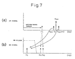
- Figure 7 is a diagram showing the spectrum of the IF signal, i.e., the output signal of the first frequency converter 3-1, and the spectrum of the BB signal passed through the baseband filter in the time division ON-OFF control type FM-CW radar of Figure 4.
- a homodyne component of a signal from a medium-range target which is not the target object, enters the IF signal frequency band and appears as signal fh which, in the beat signal band, appears as signals fh1 and fh2.
- these signals are eliminated by the BB filter since their frequencies are higher than the BB band.
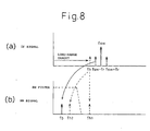
- Figure 8 is a diagram showing the spectrum of the IF signal, i.e., the output signal of the first frequency converter 3-1, and the spectrum of the BB signal passed through the baseband filter in the time division ON-OFF control type FM-CW radar of Figure 4.
- the IF signal i.e., the output signal of the first frequency converter 3-1
- Figure 8(a) when there is a long-range target, its homodyne component enters the IF frequency band and appears as signal fh.
- This signal appears as signal fh1 in the beat signal band and as signal fh2 in the BB band, as shown in Figure 8(a).
- the signal fh1 is eliminated by the BB filter as the frequency is higher than the BB band.
- the signal fh2 is not eliminated by the BB filter, and this signal, though it is a noise component, may be erroneously detected by
- FIG 9 is a diagram showing an embodiment of an FM-CW radar system according to the present invention.
- the configuration is the same as that of Figure 3, except for the inclusion of a modulating signal generator control unit 10.
- the control unit 10 under the control of the CPU 6, variably controls the skew in, for example, amplitude or period, of the modulating signal to be output from the modulating signal generator 1.
- the present invention will be described by dealing with the case of variably controlling the amplitude of the modulating signal.
- the frequency of the transmitted wave changes as shown by the solid line in part (a) of Figure 1.
- the transmitted wave is reflected from the target object and received by the antenna, the received wave being shown by the dashed line in part (a) of Figure 1.
- the received wave is shifted in frequency from the transmitted signal (i.e., produces a beat) according to the distance between the radar and the target object.
- the beat frequency component fb can be expressed by equation (1) as previously described.
- ⁇ f represents the frequency modulation amplitude
- ⁇ f can be varied by varying the amplitude of the modulating signal.
- ⁇ f is doubled and, from equation (1), fb is also doubled.
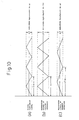
- Figure 10 is a diagram showing a triangular wave used as the modulating signal when its amplitude is varied. Part (a) shows the triangular wave with the normal amplitude (equivalent to ⁇ f), and part (b) shows the triangular wave with its amplitude doubled (equivalent to 2 ⁇ f).
- the value of the beat frequency component fb varies by n times, as described above.
- the received signal contains the noise signal fn as well as the signal fb from the target object.
- the modulating signal generator 1 from the control unit 10 controls the modulating signal generator 1 from the control unit 10 to vary ⁇ f by n times.
- the frequency fb of the signal from the target object varies by n times in response to the variation of ⁇ f.
- the frequency fn of the noise signal remains unchanged, it becomes possible to discriminate which signal is the signal from the target object. This discrimination is done by the CPU 6 in the FM-CW radar. The discrimination described below is also done by the CPU 6.
- Tm represents the period of the modulating signal. Accordingly, when the period Tm of the modulating signal is varied, for example, by n times, the beat frequency component fb varies by 1/n times.
- Figure 10(c) is a diagram showing a triangular wave used as the modulating signal when its period is varied. Part (a) shows the triangular wave with the normal period Tm, and part (c) shows the triangular wave with a period nTm which is n times the normal period Tm.
- the frequency of the transmitted wave changes as shown by the solid line in part (a) of Figure 2.
- the transmitted wave is reflected from the target object and received by the antenna, the received wave being shown by the dashed line in part (a) of Figure 2.
- the received wave is shifted in frequency from the transmitted signal (i.e., produces a beat) according to the distance between the radar and the target object.
- the beat frequency component fb can be expressed by equation (2) as previously described.
- the amplitude or period Tm of the modulating signal is varied using the control unit 10; then, as the beat frequency component fb varies correspondingly, it becomes possible to discriminate which signal is the signal reflected from the target object.
- the frequency component fb consists of the range frequency component fr and velocity frequency component fd, of which only the range frequency component fr varies in the above case. However, since the frequency component fb varies as a whole, the signal from the target object can be discriminated.
- Figure 11 is a diagram showing an embodiment of an FM-CW radar system according to the present invention.
- This embodiment concerns a single-antenna time division ON-OFF control type FM-CW radar to which the present invention is applied.
- the configuration of Figure 11 is the same as that of Figure 4, except for the inclusion of a modulating signal generator control unit 11 for the modulating signal generator 8.
- the control unit 11, under the control of the CPU 6, variably controls the frequency (period) of the modulating signal to be output from the modulating signal generator 8.
- the ON-OFF frequency (period) of the transmit-receive switching device 7 changes, and the frequency applied to the second frequency converter 3-2 also changes. Since the switching frequency fsw changes, the sideband signal frequencies fsw-fr and fsw+fr shown in Figures 6 to 8 also change, so that the signal from the target object can be discriminated.
- the frequency (period) of the modulating signal output from the modulating signal generator 8 is varied, for example, as shown in Figure 12.
- the frequency is varied in synchronism with the triangular wave being output from the other modulating signal generator 1.
- the frequency is varied as fsw1, fsw2, and fsw3 in sequence for each up/down cycle of the triangular wave.
- the ON-OFF switching frequency fsw changes, and fsw-fr and fsw+fr also change accordingly.
- other frequency components such as noise remain unchanged, so that the signal from the target object can be discriminated from other signals.
- the frequency is varied in sequence for each up/down cycle, but the frequency may be varied every plurality of up/down cycles. In the latter case, the frequency may be varied randomly.
- the frequency of the modulating signal output from the modulating signal generator 8 is varied for each half cycle (up or down) of the triangular wave.
- the frequency of the signal from the target object varies for each half cycle (up or down) of the triangular wave.
- FIG 13 is a diagram showing a two-antenna heterodyne type FM-CW radar system. Though the radar system will be described here as being the two-antenna type, the basic principle is the same for the single-antenna type.
- the system shown here differs from the configuration of Figure 11 in that two antennas, the transmitting antenna AT and the receiving antenna AR, are provided and the transmit-receive switching device is omitted because of the two-antenna system.
- an up converter 9 is provided between the voltage-controlled oscillator 2 and the first frequency converter 3-1 so that the frequency of the signal to be input to it from the modulating signal generator 8 can be controlled by the modulating signal generator control unit 11.
- the up converter 9 takes as inputs the signal of frequency f 0 from the voltage-controlled oscillator 2 and the modulating signal of frequency If1 from the modulating signal generator 8, and outputs a signal of frequency f 0 +If1 as the local signal to the first frequency converter 3-1.
- the signal frequencies fsw(If1)-fr and fsw(If2)+fr shown in Figures 6 to 8 also vary, causing the beat frequency component fb to vary accordingly, so that the signal from the target object can be discriminated.
- the frequency (period) of the modulating signal output from the modulating signal generator 8 is varied, for example, as shown in Figure 14.
- the frequency is varied in synchronism with the triangular wave being output from the other modulating signal generator 1.
- the frequency is varied as If1, If2, and If3 in sequence for each up/down cycle of the triangular wave.
- the signals Ifn+fr and Ifn-fr change at the output end of the first frequency converter 3-1, but since the noise frequency remains unchanged, the signal from the target object can be discriminated from other signals.
- the frequency is varied in sequence for each up/down cycle, but the frequency may be varied every plurality of up/down cycles. In the latter case, the frequency may be varied randomly.
- the frequency of the modulating signal output from the modulating signal generator 8 is varied for each half cycle (up or down) of the triangular wave.
- the frequency of the signal from the target object varies for each half cycle (up or down) of the triangular wave.
- Figures 15 to 16 are diagrams for explaining an embodiment in which the present invention is applied to the time division ON-OFF control type FM-CW radar. This embodiment will be described by referring to the time division ON-OFF control type FM-CW radar system shown in Figure 11.
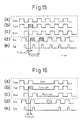
- Figure 15 is a diagram showing signal processing waveforms in a conventional art time division ON-OFF control type FM-CW radar.
- part (a) shows a waveform defining the switching timing of the transmit-receive switching device 7; the signal Ssw shown here is output from the modulating signal generator 8.
- Part (b) shows a waveform Ton defining the transmission ON timing based on Ssw, and (c) a waveform Ron defining the reception ON timing based on Ssw.
- part (d) shows a waveform SA illustrating the return timing of the transmitted signal upon reflection, and (e) a waveform SB illustrating the timing for the reflected signal to be received by the radar when the reception is ON.
- the waveform SA is delayed in timing with respect to the waveform Ton by an amount equal to the round trip time from the radar to the target object and back to the radar.
- the time interval T between the pulse shown by oblique hatching in the waveform Ton and the pulse shown by oblique hatching in the waveform SA is 2r/C, where r is the distance between the radar and the target object and C is the velocity of light.
- the pulse shown by horizontal hatching in the waveform SA for example, is returned for the oblique hatched pulse in the waveform Ton.
- the pulse time interval T' in this case is 2r'/C.
- FIG 16 is a diagram for explaining the embodiment of the present invention.
- provisions are made not to receive a reflected wave from any target other than the target object, by turning off the receiving gate when a reflected wave from a medium-range or long-range target, which is not the target object, is returned.
- a transmission/reception OFF period Toff is provided in the signal Ssw as shown in Figure 16(a). This results in the formation of a transmission OFF period Ton-off and a reception OFF period Ron-off in Ton and Ron, respectively.
- Figure 17 is a diagram for explaining an embodiment of the present invention.
- Figure 17(a) shows the transmitted waveform of the FM-CW radar.
- the transmitted waveform is triangular as shown in Figure 1(a).
- the transmitted wave has a nonlinear shape with the linearity of the conventional art waveform degraded as illustrated here; in the example shown, the waveform is shaped in the form of an arc to make the frequency deviation of the rectangular wave nonlinear.
- Figure 18(b) shows the transmitted and received waveforms according to the conventional art. These waveforms are the same as those shown in Figure 1(a). In this case, the frequency difference fr between the transmitted and received waves is the same at any point in time.
- the linearity of the transmitted wave is degraded
- the linearity of the received wave is also degraded as shown in Figure 17(c).
- the frequency difference fr between the transmitted and received waves varies with time.
- the frequency difference fr1 in the first half of the rising portion of the wave differs from the frequency difference fr2 in the second half of the rising portion, as shown, that is, fr1 > fr2.
- the difference between fr1 and fr2 increases with increasing distance to the target. Using this characteristic, a signal from a very distant target can be distinguished and eliminated from the target objects.
- Figure 18 shows frequency spectra detected. As shown, when the target is near, the spectrum exhibits a distribution such as shown by a, while when the target is distant, the spectrum exhibits a distribution such as shown by b. Accordingly, when the detected spectrum has a distribution such as shown by b, the detected target can be determined as being a very distant target and be eliminated.
- the configuration shown in Figure 9 can be used for the FM-CW radar.
- the triangular wave need not necessarily be shaped in the form of an arc as shown above, but may be shaped in any suitable form as long as it causes a difference between fr1 and fr2.
Landscapes
- Engineering & Computer Science (AREA)
- Radar, Positioning & Navigation (AREA)
- Remote Sensing (AREA)
- Computer Networks & Wireless Communication (AREA)
- Physics & Mathematics (AREA)
- General Physics & Mathematics (AREA)
- Signal Processing (AREA)
- Radar Systems Or Details Thereof (AREA)
Abstract
Description
Claims (26)
- An FM-CW radar system which frequency-modulates a voltage-controlled oscillator by applying thereto a modulating signal from a modulating signal generator, and which transmits a frequency-modulated wave and receives a reflected wave, wherein:said frequency modulating wave output from said modulating signal generator has a frequency variation skew with respect to a time axis (hereinafter called the "modulation skew"), and said system includes means for varying said modulation skew and means for discriminating a signal component varying in response to the variation of said varied modulation skew, thereby discriminating a signal related to a target object from other signals.
- An FM-CW radar system as claimed in claim 1, wherein said means for varying said modulation skew varies said modulation skew a plurality of times.
- An FM-CW radar system as claimed in claim 1, wherein said means for varying said modulation skew varies a modulation amplitude.
- An FM-CW radar system as claimed in claim 1, wherein said means for varying said modulation skew varies a modulation period.
- An FM-CW radar system as claimed in claim 1, wherein said means for varying said modulation skew varies a modulation amplitude and a modulation period.
- An FM-CW radar system as claimed in claim 1, wherein said modulating signal is a signal in the form of a triangular wave, and said means for varying said modulation skew varies said modulation skew for each pair of upward and downward slopes of said triangular wave or every plurality of said pairs.
- An FM-CW radar system as claimed in claim 1, wherein said modulating signal is a signal in the form of a triangular wave, and said means for varying said modulation skew varies said modulation skew for each of upward and downward slopes of said triangular wave.
- An FM-CW radar system as claimed in claim 1, wherein said means for varying said modulation skew switches said modulation skew randomly.
- An FM-CW radar system which frequency-modulates a voltage-controlled oscillator by applying thereto a modulating signal from a modulating signal generator, and which transmits a frequency-modulated wave by time division ON-OFF control and receives a reflected wave by time division ON-OFF control, whereinsaid system includes means for varying a frequency used to perform said time division ON-OFF control, and means for discriminating a signal component varying in response to the variation of said frequency, thereby discriminating a signal related to a target object from other signals.
- An FM-CW radar system as claimed in claim 9, wherein said time division ON-OFF control is performed either when transmitting or when receiving.
- An FM-CW radar system as claimed in claim 9, wherein said modulating signal is a signal in the form of a triangular wave, and said means for varying said transmission/reception switching frequency varies said frequency for each pair of upward and downward slopes of said triangular wave or every plurality of said pairs.
- An FM-CW radar system as claimed in claim 9, wherein said modulating signal is a signal in the form of a triangular wave, and said means for varying said transmission/reception switching frequency varies said frequency for each of upward and downward slopes of said triangular wave.
- An FM-CW radar system as claimed in claim 9, wherein said means for varying said
transmission/reception switching frequency switches said frequency randomly. - An FM-CW radar system which frequency-modulates a voltage-controlled oscillator by applying thereto a modulating signal from a modulating signal generator, and which transmits a frequency-modulated wave and receives a reflected wave, whereinsaid system is of a single-antenna type which switches between transmission and reception by time division, and includes means for varying a frequency used for said transmission/reception switching, and means for discriminating a signal component varying in response to the variation of said frequency, thereby discriminating a signal related to a target object from other signals.
- An FM-CW radar system as claimed in claim 14, wherein said modulating signal is a signal in the form of a triangular wave, and said means for varying said transmission/reception switching frequency varies said frequency for each pair of upward and downward slopes of said triangular wave or every plurality of said pairs.
- An FM-CW radar system as claimed in claim 14, wherein said modulating signal is a signal in the form of a triangular wave, and said means for varying said transmission/reception switching frequency varies said frequency for each of upward and downward slopes of said triangular wave.
- An FM-CW radar system as claimed in claim 14, wherein said means for varying said
transmission/reception switching frequency switches said frequency randomly. - A heterodyne FM-CW radar system which frequency-modulates a voltage-controlled oscillator by applying thereto a modulating signal from a modulating signal generator, and which transmits a frequency-modulated wave and receives a reflected wave, whereinsaid system includes means for varying the frequency of a downconverting signal (IF signal), and means for discriminating a signal that varies in response to the variation of the frequency of said IF signal when said frequency is varied, thereby enabling a signal related to a target object from being discriminated from other signals.
- A heterodyne FM-CW radar system as claimed in claim 18, wherein said modulating signal is a signal in the form of a triangular wave, and said means for varying the frequency of said IF signal varies said frequency for each pair of upward and downward slopes of said triangular wave or every plurality of said pairs.
- A heterodyne FM-CW radar system as claimed in claim 18, wherein said modulating signal is a signal in the form of a triangular wave, and said means for varying the frequency of said IF signal varies said frequency for each of upward and downward slopes of said triangular wave.
- An FM-CW radar system which frequency-modulates a voltage-controlled oscillator by applying thereto a modulating signal from a modulating signal generator, and which transmits a frequency-modulated wave by time division ON-OFF control and receives a reflected wave by time division ON-OFF control, whereinsaid system includes means for varying a pattern of said time division ON-OFF control, thereby suppressing signal generation due to targets other than a target object.
- An FM-CW radar system as claimed in claim 21, wherein said pattern includes a prescribed OFF period.
- An FM-CW radar system which frequency-modulates a voltage-controlled oscillator by applying thereto a modulating signal from a modulating signal generator, and which transmits a frequency-modulated wave and receives a reflected wave, whereinsaid system is of a single-antenna type which switches between transmission and reception by time division, and includes means for varying a pattern of a frequency used for said transmission/reception switching, thereby suppressing signal generation due to targets other than a target object.
- An FM-CW radar system as claimed in claim 23, wherein said pattern includes a prescribed OFF period.
- An FM-CW radar system which frequency-modulates a voltage-controlled oscillator by applying thereto a modulating signal from a modulating signal generator, and which transmits a frequency-modulated wave and receives a reflected wave, whereinsaid system includes means for making said frequency modulation vary nonlinearly and means for discriminating a frequency distribution of a received signal, and discriminates a target object based on said discriminated frequency distribution.
- An FM-CW radar system as claimed in claim 25, wherein said frequency modulation varies nonlinearly in the form of an arc.
Priority Applications (3)
| Application Number | Priority Date | Filing Date | Title |
|---|---|---|---|
| EP05021759A EP1619519B1 (en) | 2000-09-26 | 2001-09-26 | FM-CW radar system |
| EP05021760A EP1621898B1 (en) | 2000-09-26 | 2001-09-26 | FM-CW radar system |
| EP06024268A EP1757953B1 (en) | 2000-09-26 | 2001-09-26 | FM-CW radar system |
Applications Claiming Priority (3)
| Application Number | Priority Date | Filing Date | Title |
|---|---|---|---|
| JP2000292730 | 2000-09-26 | ||
| JP2000292730A JP4111667B2 (en) | 2000-09-26 | 2000-09-26 | FM-CW radar equipment |
| PCT/JP2001/008397 WO2002027350A1 (en) | 2000-09-26 | 2001-09-26 | Fm-cw radar device |
Related Child Applications (2)
| Application Number | Title | Priority Date | Filing Date |
|---|---|---|---|
| EP05021759A Division EP1619519B1 (en) | 2000-09-26 | 2001-09-26 | FM-CW radar system |
| EP05021760A Division EP1621898B1 (en) | 2000-09-26 | 2001-09-26 | FM-CW radar system |
Publications (3)
| Publication Number | Publication Date |
|---|---|
| EP1321775A1 true EP1321775A1 (en) | 2003-06-25 |
| EP1321775A4 EP1321775A4 (en) | 2005-03-23 |
| EP1321775B1 EP1321775B1 (en) | 2008-01-23 |
Family
ID=18775628
Family Applications (4)
| Application Number | Title | Priority Date | Filing Date |
|---|---|---|---|
| EP05021760A Expired - Lifetime EP1621898B1 (en) | 2000-09-26 | 2001-09-26 | FM-CW radar system |
| EP05021759A Expired - Lifetime EP1619519B1 (en) | 2000-09-26 | 2001-09-26 | FM-CW radar system |
| EP01970232A Expired - Lifetime EP1321775B1 (en) | 2000-09-26 | 2001-09-26 | Fm-cw radar device |
| EP06024268A Expired - Lifetime EP1757953B1 (en) | 2000-09-26 | 2001-09-26 | FM-CW radar system |
Family Applications Before (2)
| Application Number | Title | Priority Date | Filing Date |
|---|---|---|---|
| EP05021760A Expired - Lifetime EP1621898B1 (en) | 2000-09-26 | 2001-09-26 | FM-CW radar system |
| EP05021759A Expired - Lifetime EP1619519B1 (en) | 2000-09-26 | 2001-09-26 | FM-CW radar system |
Family Applications After (1)
| Application Number | Title | Priority Date | Filing Date |
|---|---|---|---|
| EP06024268A Expired - Lifetime EP1757953B1 (en) | 2000-09-26 | 2001-09-26 | FM-CW radar system |
Country Status (7)
| Country | Link |
|---|---|
| US (3) | US7002512B2 (en) |
| EP (4) | EP1621898B1 (en) |
| JP (1) | JP4111667B2 (en) |
| KR (1) | KR100597343B1 (en) |
| CN (1) | CN1260578C (en) |
| DE (4) | DE60132605T2 (en) |
| WO (1) | WO2002027350A1 (en) |
Cited By (2)
| Publication number | Priority date | Publication date | Assignee | Title |
|---|---|---|---|---|
| EP1777549A1 (en) | 2005-10-24 | 2007-04-25 | Mitsubishi Electric Information Technology Centre Europe B.V. | Object ranging |
| CN105676193A (en) * | 2014-11-20 | 2016-06-15 | 中国航空工业集团公司雷华电子技术研究所 | Multi-frequency signal generation method based on DDS chip |
Families Citing this family (42)
| Publication number | Priority date | Publication date | Assignee | Title |
|---|---|---|---|---|
| JP3495355B2 (en) * | 2001-11-05 | 2004-02-09 | 三菱電機株式会社 | Pulse radar equipment |
| JP2003161775A (en) * | 2001-11-26 | 2003-06-06 | Mitsubishi Electric Corp | Target detection method and radar device |
| JP3964362B2 (en) * | 2002-07-26 | 2007-08-22 | 株式会社日立製作所 | Radio wave radar device and inter-vehicle distance control device |
| JP3688255B2 (en) * | 2002-09-20 | 2005-08-24 | 株式会社日立製作所 | In-vehicle radio radar apparatus and signal processing method thereof |
| JP2004226158A (en) * | 2003-01-21 | 2004-08-12 | Fujitsu Ten Ltd | Fm-cw radar device |
| JP4062135B2 (en) * | 2003-03-14 | 2008-03-19 | 株式会社村田製作所 | High frequency oscillation device, radio device and radar |
| DE10350553A1 (en) * | 2003-10-29 | 2005-06-02 | Robert Bosch Gmbh | Device and method for detecting, detecting and / or evaluating at least one object |
| JP4447946B2 (en) * | 2004-03-22 | 2010-04-07 | 富士通テン株式会社 | Radar equipment |
| DE102004046632A1 (en) * | 2004-09-25 | 2006-03-30 | Robert Bosch Gmbh | Antenna radar system with heterodyne frequency conversion (mixing) of input / output signals |
| JP2006010329A (en) * | 2004-06-22 | 2006-01-12 | Fujitsu Ten Ltd | Timing adjustment method for radar and radar with automatic timing adjustment function |
| US7180580B2 (en) * | 2004-07-02 | 2007-02-20 | Venkata Guruprasad | Passive distance measurement using spectral phase gradients |
| JP2006078388A (en) * | 2004-09-10 | 2006-03-23 | Fujitsu Ten Ltd | Radar system |
| JP4652086B2 (en) * | 2005-03-04 | 2011-03-16 | 富士通テン株式会社 | Radar equipment |
| DE102005012945A1 (en) * | 2005-03-21 | 2006-09-28 | Robert Bosch Gmbh | Method and apparatus for distance and relative velocity measurement of multiple objects |
| WO2006134912A1 (en) | 2005-06-17 | 2006-12-21 | Murata Manufacturing Co., Ltd. | Radar apparatus |
| CN101223747B (en) * | 2005-07-13 | 2011-06-08 | 文卡达·古鲁普拉赛德 | Distance-dependent spectra using uniform sampling spectrometry |
| JP5221142B2 (en) * | 2005-10-07 | 2013-06-26 | 株式会社東芝 | Adjustment method between radar device and radar site |
| GB0523676D0 (en) * | 2005-11-21 | 2005-12-28 | Plextek Ltd | Radar system |
| DE602006002865D1 (en) * | 2005-12-07 | 2008-11-06 | Korea Electronics Telecomm | Transmitter Receiver Module and Milimeter Wave Area FMCW radar using this module |
| KR100772927B1 (en) * | 2006-09-29 | 2007-11-02 | 한국전자통신연구원 | Heterodyne RF Transceiver for Radar Sensor |
| JP4977443B2 (en) * | 2006-10-31 | 2012-07-18 | 日立オートモティブシステムズ株式会社 | Radar apparatus and radar detection method |
| JP4871104B2 (en) * | 2006-11-24 | 2012-02-08 | 日立オートモティブシステムズ株式会社 | Radar apparatus and signal processing method |
| JP4913646B2 (en) * | 2007-03-26 | 2012-04-11 | 富士通テン株式会社 | Radar apparatus, radar apparatus control apparatus, radar apparatus control program, and radar apparatus control method |
| US7737885B2 (en) * | 2007-08-01 | 2010-06-15 | Infineon Technologies Ag | Ramp linearization for FMCW radar using digital down-conversion of a sampled VCO signal |
| JP4724694B2 (en) | 2007-08-08 | 2011-07-13 | 日立オートモティブシステムズ株式会社 | Radio radar equipment |
| DE102007043535A1 (en) * | 2007-09-12 | 2009-03-19 | Robert Bosch Gmbh | FMCW radar locating device and corresponding FMCW radar locating method |
| JP5319145B2 (en) * | 2008-03-25 | 2013-10-16 | 株式会社東芝 | Radar device and control method of radar device |
| EP2189809A1 (en) * | 2008-11-24 | 2010-05-26 | Mitsubishi Electric R&D Centre Europe B.V. | Object ranging |
| JP5183661B2 (en) * | 2010-03-29 | 2013-04-17 | 三菱電機株式会社 | In-vehicle radar system |
| KR101199169B1 (en) * | 2011-01-12 | 2012-11-07 | 주식회사 만도 | Method and radar apparatus for detecting target object |
| JP5413388B2 (en) | 2011-03-09 | 2014-02-12 | 株式会社デンソー | Power supply device and radar system |
| KR101207718B1 (en) | 2011-03-15 | 2012-12-03 | 주식회사 만도 | frequency modulated continuous wave radar system |
| TWI448715B (en) | 2012-07-30 | 2014-08-11 | Univ Nat Chiao Tung | Motion parameter estimating method, angle estimating method and determination method |
| JP6222523B2 (en) * | 2014-03-11 | 2017-11-01 | 日本電気株式会社 | Moving target extraction system, moving target extraction method, information processing apparatus, control method thereof, and control program |
| KR101645123B1 (en) * | 2015-01-20 | 2016-08-12 | 재단법인대구경북과학기술원 | Method and apparatus for detecting distance and speed of target in high-resolution |
| EP3208579B1 (en) * | 2016-02-22 | 2020-01-29 | VEGA Grieshaber KG | Reduction of power spikes in the average power range of fill level measuring devices |
| US10585182B2 (en) * | 2017-03-24 | 2020-03-10 | GM Global Technology Operations LLC | Velocity measurement with asymmetric doppler spectrum |
| US11662451B2 (en) * | 2018-01-17 | 2023-05-30 | Mitsubishi Electric Corporation | Radar apparatus and computer readable medium |
| WO2019224880A1 (en) * | 2018-05-21 | 2019-11-28 | 三菱電機株式会社 | Radar device |
| KR20220109605A (en) | 2021-01-29 | 2022-08-05 | 한국전자통신연구원 | A radar device operating in dual mode and operation method thereof |
| KR102735805B1 (en) | 2022-01-17 | 2024-11-28 | 영남대학교 산학협력단 | Continuous wave radar based distance measuring device and method |
| NL2031184B1 (en) * | 2022-03-08 | 2023-09-18 | Univ Delft Tech | Frequency modulated continuous wave receiver, transmitter, transceiver and methods |
Family Cites Families (31)
| Publication number | Priority date | Publication date | Assignee | Title |
|---|---|---|---|---|
| US3109172A (en) * | 1960-08-10 | 1963-10-29 | Kermit E Hardinger | Low altitude f. m. altimeter |
| US4142189A (en) * | 1965-01-07 | 1979-02-27 | The Magnavox Company | Radar system |
| US3703004A (en) * | 1971-07-01 | 1972-11-14 | Singer Co | Leakage filter for frequency modulated continuous wave doppler radar system |
| US6476755B1 (en) * | 1980-04-28 | 2002-11-05 | Bae Systems Information And Electronic Systems Integration Inc. | Communications jamming receiver |
| US4620192A (en) * | 1983-09-29 | 1986-10-28 | Raytheon Company | Continuous wave radar with ranging capability |
| FR2566921B1 (en) * | 1984-06-29 | 1987-12-18 | Thomson Csf | FREQUENCY MODULATED RADIOALTIMETER |
| GB2350740B (en) * | 1986-07-23 | 2001-04-04 | Philips Electronic Associated | Radar apparatus |
| US4895441A (en) * | 1987-03-19 | 1990-01-23 | Pandel Instruments, Inc. | Method and apparatus for precision ranging |
| JP2881231B2 (en) * | 1989-02-10 | 1999-04-12 | 本田技研工業株式会社 | FM radar equipment |
| JP2909822B2 (en) * | 1989-02-10 | 1999-06-23 | 本田技研工業株式会社 | FM radar equipment |
| US4935742A (en) * | 1989-04-19 | 1990-06-19 | Jonathan Marin | Automatic radar generator |
| DE4111189C1 (en) * | 1991-04-06 | 1992-09-17 | Hoechst Ceramtec Ag, 8672 Selb, De | |
| JP2981312B2 (en) * | 1991-08-08 | 1999-11-22 | 富士通株式会社 | FM-CW radar device |
| JP2657020B2 (en) * | 1992-03-17 | 1997-09-24 | 富士通株式会社 | FM-CW radar device |
| JP2701107B2 (en) | 1992-04-21 | 1998-01-21 | 本田技研工業株式会社 | FM radar equipment |
| US5387917A (en) * | 1992-12-11 | 1995-02-07 | Honeywell Inc. | Radar fuze |
| JPH085733A (en) | 1994-06-22 | 1996-01-12 | Hitachi Ltd | Radar equipment |
| JP2768439B2 (en) | 1994-11-08 | 1998-06-25 | 本田技研工業株式会社 | FM-CW type multi-beam radar device |
| JP3302848B2 (en) * | 1994-11-17 | 2002-07-15 | 本田技研工業株式会社 | In-vehicle radar device |
| JP3104559B2 (en) * | 1995-02-08 | 2000-10-30 | トヨタ自動車株式会社 | Automotive radar equipment |
| JP3485382B2 (en) * | 1995-06-01 | 2004-01-13 | 富士通テン株式会社 | FM-CW radar device |
| JP3639020B2 (en) | 1995-11-21 | 2005-04-13 | 富士通株式会社 | FM-CW radar equipment |
| JP3565646B2 (en) * | 1996-02-01 | 2004-09-15 | 富士通テン株式会社 | FM-CW radar |
| JP3347571B2 (en) * | 1996-03-12 | 2002-11-20 | 富士通株式会社 | Radar equipment |
| JP3206437B2 (en) | 1996-07-04 | 2001-09-10 | 日本電気株式会社 | FM-CW radar apparatus and object distance measuring method |
| EP0932838B1 (en) * | 1996-10-17 | 2007-02-14 | Saab Bofors Dynamics AB | Procedure for the elimination of interference in a radar unit of the fmcw type |
| JP3061261B2 (en) * | 1997-04-01 | 2000-07-10 | 本田技研工業株式会社 | FM radar equipment |
| JP3398745B2 (en) * | 1997-08-21 | 2003-04-21 | 三菱電機株式会社 | Automotive radar equipment |
| JP3011164B2 (en) * | 1997-11-14 | 2000-02-21 | 日本電気株式会社 | Radar equipment |
| JP3804253B2 (en) * | 1998-02-16 | 2006-08-02 | 株式会社デンソー | Radar device, voltage controlled oscillator, and voltage controlled oscillator control method |
| JPH11287853A (en) * | 1998-04-03 | 1999-10-19 | Denso Corp | Radar equipment |
-
2000
- 2000-09-26 JP JP2000292730A patent/JP4111667B2/en not_active Expired - Lifetime
-
2001
- 2001-09-26 KR KR1020027006484A patent/KR100597343B1/en not_active Expired - Fee Related
- 2001-09-26 EP EP05021760A patent/EP1621898B1/en not_active Expired - Lifetime
- 2001-09-26 DE DE60132605T patent/DE60132605T2/en not_active Expired - Lifetime
- 2001-09-26 EP EP05021759A patent/EP1619519B1/en not_active Expired - Lifetime
- 2001-09-26 DE DE60140329T patent/DE60140329D1/en not_active Expired - Lifetime
- 2001-09-26 DE DE60132934T patent/DE60132934T2/en not_active Expired - Lifetime
- 2001-09-26 US US10/148,059 patent/US7002512B2/en not_active Expired - Lifetime
- 2001-09-26 DE DE60132386T patent/DE60132386T2/en not_active Expired - Lifetime
- 2001-09-26 CN CNB018028942A patent/CN1260578C/en not_active Expired - Fee Related
- 2001-09-26 EP EP01970232A patent/EP1321775B1/en not_active Expired - Lifetime
- 2001-09-26 EP EP06024268A patent/EP1757953B1/en not_active Expired - Lifetime
- 2001-09-26 WO PCT/JP2001/008397 patent/WO2002027350A1/en not_active Ceased
-
2003
- 2003-08-22 US US10/646,905 patent/US7221309B2/en not_active Expired - Fee Related
-
2005
- 2005-12-01 US US11/293,332 patent/US7183968B2/en not_active Expired - Lifetime
Cited By (4)
| Publication number | Priority date | Publication date | Assignee | Title |
|---|---|---|---|---|
| EP1777549A1 (en) | 2005-10-24 | 2007-04-25 | Mitsubishi Electric Information Technology Centre Europe B.V. | Object ranging |
| EP1777549B1 (en) * | 2005-10-24 | 2012-10-03 | Mitsubishi Electric Information Technology Centre Europe B.V. | Object ranging |
| US8410976B2 (en) | 2005-10-24 | 2013-04-02 | Mitsubishi Electric Corporation | Frequency-modulated interrupted continuous wave radar using pulses derived from a frequency-modulated signal in which the rate of frequency change increases at the boundary of a pulse repetition interval |
| CN105676193A (en) * | 2014-11-20 | 2016-06-15 | 中国航空工业集团公司雷华电子技术研究所 | Multi-frequency signal generation method based on DDS chip |
Also Published As
| Publication number | Publication date |
|---|---|
| DE60132386T2 (en) | 2009-01-08 |
| JP4111667B2 (en) | 2008-07-02 |
| EP1757953B1 (en) | 2009-10-28 |
| US20060103571A1 (en) | 2006-05-18 |
| EP1619519A1 (en) | 2006-01-25 |
| DE60132934T2 (en) | 2009-02-12 |
| EP1621898B1 (en) | 2008-02-20 |
| DE60132605D1 (en) | 2008-03-13 |
| WO2002027350A1 (en) | 2002-04-04 |
| EP1321775B1 (en) | 2008-01-23 |
| DE60132934D1 (en) | 2008-04-03 |
| CN1260578C (en) | 2006-06-21 |
| KR100597343B1 (en) | 2006-07-10 |
| US20050184903A1 (en) | 2005-08-25 |
| US7183968B2 (en) | 2007-02-27 |
| EP1757953A1 (en) | 2007-02-28 |
| KR20020056931A (en) | 2002-07-10 |
| US7002512B2 (en) | 2006-02-21 |
| EP1619519B1 (en) | 2008-01-09 |
| US20020180632A1 (en) | 2002-12-05 |
| DE60140329D1 (en) | 2009-12-10 |
| JP2002098753A (en) | 2002-04-05 |
| US7221309B2 (en) | 2007-05-22 |
| EP1621898A3 (en) | 2006-02-15 |
| DE60132605T2 (en) | 2008-05-21 |
| EP1621898A2 (en) | 2006-02-01 |
| DE60132386D1 (en) | 2008-02-21 |
| EP1321775A4 (en) | 2005-03-23 |
| CN1392957A (en) | 2003-01-22 |
Similar Documents
| Publication | Publication Date | Title |
|---|---|---|
| EP1621898B1 (en) | FM-CW radar system | |
| US7148840B2 (en) | Radar apparatus, radar apparatus controlling method | |
| US7460058B2 (en) | Radar | |
| US7187321B2 (en) | Interference determination method and FMCW radar using the same | |
| EP1376153A1 (en) | Fm-cw radar processing device | |
| JP5552212B2 (en) | Radar device | |
| JPH0540169A (en) | FM-CW radar device | |
| US20090002223A1 (en) | Transmit-Receive FM-CW Radar Apparatus | |
| JPH04343084A (en) | Fm-cw radar device | |
| US6972711B2 (en) | Transmit-receive FM-CW radar apparatus | |
| US7034745B2 (en) | Radar apparatus equipped with abnormality detection function | |
| US20050174279A1 (en) | Device and method for the single sideband modulation of a radar device | |
| JP3709826B2 (en) | Radar | |
| JP4085840B2 (en) | Radar equipment | |
| JP4330636B2 (en) | FM-CW radar equipment | |
| JP4330634B2 (en) | FM-CW radar equipment | |
| JP4330635B2 (en) | FM-CW radar equipment | |
| JP4330633B2 (en) | FM-CW radar equipment | |
| JP3911266B2 (en) | Radar apparatus, radar apparatus target measurement method, and radar apparatus target measurement program | |
| WO2025117459A1 (en) | Noise suppression and orthogonal waveform generation using phase division in a fmcw mimo radar system |
Legal Events
| Date | Code | Title | Description |
|---|---|---|---|
| PUAI | Public reference made under article 153(3) epc to a published international application that has entered the european phase |
Free format text: ORIGINAL CODE: 0009012 |
|
| 17P | Request for examination filed |
Effective date: 20020524 |
|
| AK | Designated contracting states |
Designated state(s): AT BE CH CY DE DK ES FI FR GB GR IE IT LI LU MC NL PT SE TR |
|
| AX | Request for extension of the european patent |
Extension state: AL LT LV MK RO SI |
|
| RBV | Designated contracting states (corrected) |
Designated state(s): DE FR GB |
|
| RIC1 | Information provided on ipc code assigned before grant |
Ipc: 7G 01S 13/34 A Ipc: 7G 01S 7/35 B Ipc: 7F 41G 7/20 B Ipc: 7G 01S 13/58 B |
|
| A4 | Supplementary search report drawn up and despatched |
Effective date: 20050203 |
|
| 17Q | First examination report despatched |
Effective date: 20050614 |
|
| 17Q | First examination report despatched |
Effective date: 20050614 |
|
| GRAP | Despatch of communication of intention to grant a patent |
Free format text: ORIGINAL CODE: EPIDOSNIGR1 |
|
| GRAS | Grant fee paid |
Free format text: ORIGINAL CODE: EPIDOSNIGR3 |
|
| GRAA | (expected) grant |
Free format text: ORIGINAL CODE: 0009210 |
|
| AK | Designated contracting states |
Kind code of ref document: B1 Designated state(s): DE FR GB |
|
| REG | Reference to a national code |
Ref country code: GB Ref legal event code: FG4D |
|
| REF | Corresponds to: |
Ref document number: 60132605 Country of ref document: DE Date of ref document: 20080313 Kind code of ref document: P |
|
| ET | Fr: translation filed | ||
| PLBE | No opposition filed within time limit |
Free format text: ORIGINAL CODE: 0009261 |
|
| STAA | Information on the status of an ep patent application or granted ep patent |
Free format text: STATUS: NO OPPOSITION FILED WITHIN TIME LIMIT |
|
| 26N | No opposition filed |
Effective date: 20081024 |
|
| REG | Reference to a national code |
Ref country code: FR Ref legal event code: PLFP Year of fee payment: 16 |
|
| REG | Reference to a national code |
Ref country code: FR Ref legal event code: PLFP Year of fee payment: 17 |
|
| REG | Reference to a national code |
Ref country code: FR Ref legal event code: PLFP Year of fee payment: 18 |
|
| PGFP | Annual fee paid to national office [announced via postgrant information from national office to epo] |
Ref country code: DE Payment date: 20180911 Year of fee payment: 18 Ref country code: FR Payment date: 20180813 Year of fee payment: 18 |
|
| PGFP | Annual fee paid to national office [announced via postgrant information from national office to epo] |
Ref country code: GB Payment date: 20180926 Year of fee payment: 18 |
|
| REG | Reference to a national code |
Ref country code: DE Ref legal event code: R119 Ref document number: 60132605 Country of ref document: DE |
|
| PG25 | Lapsed in a contracting state [announced via postgrant information from national office to epo] |
Ref country code: DE Free format text: LAPSE BECAUSE OF NON-PAYMENT OF DUE FEES Effective date: 20200401 |
|
| GBPC | Gb: european patent ceased through non-payment of renewal fee |
Effective date: 20190926 |
|
| PG25 | Lapsed in a contracting state [announced via postgrant information from national office to epo] |
Ref country code: GB Free format text: LAPSE BECAUSE OF NON-PAYMENT OF DUE FEES Effective date: 20190926 Ref country code: FR Free format text: LAPSE BECAUSE OF NON-PAYMENT OF DUE FEES Effective date: 20190930 |