EP1321727A2 - Heat pump type air conditioner - Google Patents
Heat pump type air conditioner Download PDFInfo
- Publication number
- EP1321727A2 EP1321727A2 EP02023360A EP02023360A EP1321727A2 EP 1321727 A2 EP1321727 A2 EP 1321727A2 EP 02023360 A EP02023360 A EP 02023360A EP 02023360 A EP02023360 A EP 02023360A EP 1321727 A2 EP1321727 A2 EP 1321727A2
- Authority
- EP
- European Patent Office
- Prior art keywords
- coolant
- heat exchangers
- indoor
- port
- air conditioner
- Prior art date
- Legal status (The legal status is an assumption and is not a legal conclusion. Google has not performed a legal analysis and makes no representation as to the accuracy of the status listed.)
- Granted
Links
Images



Classifications
-
- F—MECHANICAL ENGINEERING; LIGHTING; HEATING; WEAPONS; BLASTING
- F25—REFRIGERATION OR COOLING; COMBINED HEATING AND REFRIGERATION SYSTEMS; HEAT PUMP SYSTEMS; MANUFACTURE OR STORAGE OF ICE; LIQUEFACTION SOLIDIFICATION OF GASES
- F25B—REFRIGERATION MACHINES, PLANTS OR SYSTEMS; COMBINED HEATING AND REFRIGERATION SYSTEMS; HEAT PUMP SYSTEMS
- F25B29/00—Combined heating and refrigeration systems, e.g. operating alternately or simultaneously
-
- F—MECHANICAL ENGINEERING; LIGHTING; HEATING; WEAPONS; BLASTING
- F25—REFRIGERATION OR COOLING; COMBINED HEATING AND REFRIGERATION SYSTEMS; HEAT PUMP SYSTEMS; MANUFACTURE OR STORAGE OF ICE; LIQUEFACTION SOLIDIFICATION OF GASES
- F25B—REFRIGERATION MACHINES, PLANTS OR SYSTEMS; COMBINED HEATING AND REFRIGERATION SYSTEMS; HEAT PUMP SYSTEMS
- F25B13/00—Compression machines, plants or systems, with reversible cycle
-
- F—MECHANICAL ENGINEERING; LIGHTING; HEATING; WEAPONS; BLASTING
- F25—REFRIGERATION OR COOLING; COMBINED HEATING AND REFRIGERATION SYSTEMS; HEAT PUMP SYSTEMS; MANUFACTURE OR STORAGE OF ICE; LIQUEFACTION SOLIDIFICATION OF GASES
- F25B—REFRIGERATION MACHINES, PLANTS OR SYSTEMS; COMBINED HEATING AND REFRIGERATION SYSTEMS; HEAT PUMP SYSTEMS
- F25B2313/00—Compression machines, plants or systems with reversible cycle not otherwise provided for
- F25B2313/023—Compression machines, plants or systems with reversible cycle not otherwise provided for using multiple indoor units
- F25B2313/0233—Compression machines, plants or systems with reversible cycle not otherwise provided for using multiple indoor units in parallel arrangements
-
- F—MECHANICAL ENGINEERING; LIGHTING; HEATING; WEAPONS; BLASTING
- F25—REFRIGERATION OR COOLING; COMBINED HEATING AND REFRIGERATION SYSTEMS; HEAT PUMP SYSTEMS; MANUFACTURE OR STORAGE OF ICE; LIQUEFACTION SOLIDIFICATION OF GASES
- F25B—REFRIGERATION MACHINES, PLANTS OR SYSTEMS; COMBINED HEATING AND REFRIGERATION SYSTEMS; HEAT PUMP SYSTEMS
- F25B2313/00—Compression machines, plants or systems with reversible cycle not otherwise provided for
- F25B2313/025—Compression machines, plants or systems with reversible cycle not otherwise provided for using multiple outdoor units
- F25B2313/0251—Compression machines, plants or systems with reversible cycle not otherwise provided for using multiple outdoor units being defrosted alternately
Definitions
- the present invention relates to a heat pump type air conditioner, and in particular to a heat pump type air conditioner which is capable of performing an indoor heating operation while performing an outdoor defrosting operation.
- a heat pump type air conditioner is an air conditioner performable both a cooling operation and a heating operation. Because it includes an evaporator and a condenser, etc., it can perform a heating operation as well as a cooling operation by reversing a cooling cycle.
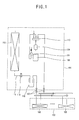
- Figure 1 illustrates a cooling cycle of the conventional heat pump type air conditioner.
- the conventional heat pump type air conditioner includes an indoor unit 102 placed indoors and performing cooling or heating and an outdoor unit 104 placed outdoors and performing a heat exchange operation.
- the indoor unit 102 includes at least one indoor heat exchanger 106 installed in each room and performing cooling and heating operations.
- the outdoor unit 104 includes a compressor 108 for compressing a coolant; a four-way valve 110 for switching a flow of the coolant normally or reversely; an outdoor heat exchanger 112 used as a condenser in cooling and an evaporator in heating; and an expansion valve 116 installed at a coolant pipe 114 for connecting the outdoor heat exchanger 112 with the indoor heat exchanger 106 and turning coolant gas into low temperature-low pressure state.
- a liquid receiver 118 for dividing the coolant into liquid and gas is installed at the rear of the expansion valve 116, and an opening/closing valve 120 is installed at the coolant pipe 114 between the outdoor heat exchanger 112 and the indoor heat exchanger 106 in order to open the coolant supply to the indoor unit 102 and the coolant discharge to the outdoor unit 104.
- An accumulator 122 for turning the coolant into a gas state is installed at a certain side of the compressor 108, and an oil divider 124 is installed at a discharge side of the compressor 108.
- the coolant gas compressed in the compressor 108 passes the four-way valve 110, flows into the outdoor heat exchanger 112, is converted into a low temperature-low pressure state while passing the expansion valve 116 and flows into the indoor heat exchanger 106. And, the coolant gas evaporated in the indoor heat exchanger 106 performs the indoor cooling operation while performing heat-exchange with indoor air and is sucked into the compressor 108 through the four-way valve 110 and is circulated again.
- the coolant gas discharged from the compressor 108 flows into the indoor heat exchanger 106 through the four-way valve 110, is condensed and performs the indoor heating operation while performing heat-exchange with indoor air.
- the coolant passing the indoor heat exchanger 106 is turned into a low temperature-low pressure state and is evaporated through the outdoor heat exchanger 112. The evaporated coolant gas is sucked into the compressor 108 through the four-way valve 110 and is circulated again.
- the outdoor heat exchanger 112 in order to perform a defrosting operation, by performing the cooling operation for a certain time, the outdoor heat exchanger 112 is used as a condenser, and accordingly frost formed at the outdoor heat exchanger 112 melts by the condensing heat.
- a heat pump type air conditioner which is capable of maintaining a room temperature constantly by including two outdoor heat exchangers and performing a heating operation with one heat exchanger when the other heat exchanger performs a defrosting operation.
- a heat pump type air conditioner which is capable of improving a cooling/heating performance by varying a heat exchange performance of each indoor heat exchanger according to a size of each room.
- a heat pump type air conditioner includes a compressor for compressing a coolant; a four-way valve for switching a flow of the coolant normally or reversely; a first and a second outdoor heat exchangers respectively installed outdoors, used as a condenser in cooling and used as an evaporator in heating; plural indoor heat exchangers respectively installed at each indoor space and performing a cooling/heating operation; a first and a second outdoor expansion valves respectively installed at coolant pipes for connecting the first and second outdoor heat exchangers with the indoor heat exchangers in order to turn the coolant into a low temperature-low pressure state and open/close the coolant pipes; a control unit for making one of the first and second outdoor heat exchangers perform a defrosting operation and making the rest perform a heating operation by controlling the first and second outdoor expansion valves; and plural indoor expansion valves respectively installed at the indoor coolant pipes and variously adjusting a quantity of the coolant flowing into the plural indoor heat exchangers.
- the four-way valve includes a first port connected to a discharge side of the compressor; a second port connected to the indoor heat exchangers by a first coolant pipe; a third port connected to the first and second outdoor heat exchangers by a second and a third coolant pipes; and a fourth port connected to a suction side of the compressor; wherein the first port communicates with the third port and the second port communicates with the fourth port in the cooling operation, and the first port communicates with the second port and the third port communicates with the fourth port in the heating operation.
- the second coolant pipe connects the first outdoor heat exchanger with the four-way valve
- a fourth coolant pipe connects the first outdoor heat exchanger with the indoor heat exchangers
- a sixth coolant pipe connects the fourth coolant pipe with the second port of the four-way valve
- a first valve is installed at the sixth coolant pipe in order to open/close it according to an electric signal transmitted from the control unit.
- the first valve is a solenoid type for opening the sixth coolant pipe according to an electric signal applied from the control unit.
- the third coolant pipe connects the second outdoor heat exchanger with the four-way valve
- a fifth coolant pipe connects the second outdoor heat exchanger with the indoor heat exchangers
- a seventh coolant pipe connects the fifth coolant pipe with the second port of the four-way valve
- a second valve is installed at the seventh coolant pipe to open/close it according to an electric signal transmitted from the control unit.
- the second valve is a solenoid type for opening the seventh coolant pipe according to an electric signal applied from the control unit.
- the control unit opens the sixth coolant pipe by operating the first valve and closes the fourth coolant pipe by operating the first outdoor expansion valve in the defrosting operation of the first outdoor heat exchanger.
- the control unit opens the seventh coolant pipe by operating the second valve and closes the fifth coolant pipe by operating the second outdoor expansion valve in the defrosting operation of the second outdoor heat exchanger.
- Figure 2 illustrates a construction of a cooling cycle of a heat pump type air conditioner in accordance with the present invention.
- the heat pump type air conditioner in accordance with the present invention includes an indoor unit 2 installed indoors and performing a cooling or a heating operation; an outdoor unit 4 installed outdoors, connected to the indoor unit 2 by a coolant pipe and performing a heat exchange operation; and a control unit 6 respectively controlling a cooling operation, a heating operation and a defrosting operation.
- the indoor unit 2 includes plural indoor heat exchangers 8a, 8b respectively installed at each indoor space; and plural indoor expansion valves 10a, 10b for turning the coolant into a low temperature-low pressure state and adjusting a flow amount of the coolant supplied to each indoor heat exchanger 8a, 8b.
- the outdoor unit 4 includes a compressor 12 for compressing the coolant; a four-way valve 14 for switching a flow of the coolant into a normal direction or a reverse direction; a first and a second outdoor heat exchangers 16, 18 used as a condenser in a cooling operation and an evaporator in a heating operation; and a first and a second outdoor expansion valves 20, 22 respectively installed at coolant pipes connecting the first and second heat exchangers 16, 18 with the indoor heat exchangers 8a, 8b, turning the coolant gas into a low temperature-low pressure state and opening/closing the coolant pipes.
- An accumulator 24 for sucking the coolant is installed at a suction side of the compressor 12, and an oil divider 26 is installed at a discharge side of the compressor 12.
- a liquid receiver 28 is connected to the coolant pipes connecting the first and second outdoor heat exchangers 16, 18 with the indoor heat exchangers 8a, 8b.
- the four-way valve 14 includes a first port 30 connected to the discharge side of the compressor 12; a second port 32 connected to the indoor heat exchangers 8a, 8b; a third port 34 connected to the first and second outdoor heat exchangers 16, 18; and a fourth port 36 connected to the suction part of the compressor 12.
- a first coolant pipe 40 connects the second port 32 of the four-way valve 14 with the indoor heat exchangers 8a, 8b, a second coolant pipe 42 connects the third port 34 with the first outdoor heat exchanger 16, and a third coolant pipe 44 connects the third port 34 with the second outdoor heat exchanger 18.
- a fourth coolant pipe 46 connects the first outdoor heat exchanger 16 with the indoor heat exchangers 8a, 8b
- a fifth coolant pipe 48 connects the second outdoor heat exchanger 18 with the indoor heat exchanger 8a, 8b.
- a first outdoor expansion valve 20 is installed at the fourth coolant pipe 46
- a second outdoor expansion valve 22 is installed at the fifth coolant pipe 48.
- the fourth coolant pipe 46 and the fifth coolant pipe 48 get together and is connected to the liquid receiver 28, and plural indoor expansion valves 10a, 10b are installed at the coolant pipes connecting the liquid receiver 28 with each indoor heat exchanger 8a, 8b.
- an opening/closing valve 52 for intermitting a coolant flow is respectively installed at a suction pipe and a discharge pipe connected to the indoor heat exchangers 8a, 8b.
- a sixth coolant pipe 54 connects the fourth coolant pipe 46 with the first coolant pipe 40, and a seventh coolant pipe 56 connects the fifth coolant pipe 48 with the first coolant pipe 40.
- a first valve 58 is installed at the sixth coolant pipe 54 to open/close it, and a second valve 60 is installed at the seventh coolant pipe 56 to open/close it.
- first and second valves 58, 60 prefferably be a solenoid type for respectively opening the sixth and seventh coolant pipes 54, 56 when an electric signal is applied from the control unit 6.
- FIG. 3 is a block diagram illustrating a control structure of the heat pump type air conditioner in accordance with the present invention.
- the heat pump type air conditioner in accordance with the present invention includes an operation selecting unit 70 operated by a user; a first sensing unit 72 for sensing whether the first outdoor heat exchanger 18 is covered with frost not less than a setting value; a second sensing unit 74 for sensing whether the second outdoor heat exchanger 18 is covered with frost not less than a setting value; and a control unit 6 for performing the cooling operation, the heating operation and the defrosting operation in accordance with a signal transmitted from the operation selecting unit 70, the first and second sensing units 72, 74.
- first and second sensing units 72, 74 can be applied to the first and second sensing units 72, 74, and any method capable of grasping whether the first outdoor heat exchanger 16 and the second outdoor heat exchanger 18 are covered with frost can be applied.
- the control unit 6 performs the cooling/heating switching by operating the four-way valve 14 according to the operation of the operation selecting unit 70.
- the control unit 6 makes one of the first outdoor heat exchanger 20 and the second outdoor heat exchanger 22 perform the defrosting operation and makes the rest perform the heating operation according to the signal received from the first and second sensing units 72, 74.
- control unit 6 adjusts a quantity of the coolant supplied to each indoor heat exchanger 8a, 8b by adjusting opening of the indoor expansion valves 10a, 10b.
- the control unit 6 respectively connects the second port 32 and the fourth port 36 with the first port 30 and the third port 34 by operating the four-way valve 14. And, the first and second valves 58, 60 maintain the closed state.
- the compressed coolant flows into the first port 30 of the four-way valve 14, is discharged to the third port 34, respectively flows into the first outdoor heat exchanger 16 and the second outdoor heat exchanger 18 through the second and third coolant pipes 42, 44 and performs the heat exchange.
- the coolant finishing the heat exchange is discharged into the four and fifth coolant pipes 46, 48, is turned into the low temperature-low pressure state while passing the first and second outdoor expansion valves 20, 22 and flows into each indoor heat exchanger 8a, 8b.
- each indoor heat exchanger 8a, 8b performs the indoor cooling while performing the heat exchange with indoor air, flows into the second port 32 of the four-way valve 14 through the first coolant pipe 40, is discharged into the third port 34, flows into the compressor 12, is compressed, and accordingly the coolant is circulated again.
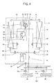
- Figure 4 is a state diagram illustrating the heating operation of the heat pump type air conditioner in accordance with the present invention.
- the control unit 6 connects the first port 30 of the four-way valve 14 with the second port 32, connects the third port 34 with the fourth port 36, and accordingly the coolant flows in the reverse direction.
- the first valve 58 and the second valve 60 are in the closed state.
- the coolant compressed by the operation of the compressor 12 flows into the first port 30 of the four-way valve 14, is discharged into the second port 32, flows into the indoor heat exchangers 8a, 8b through the first coolant pipe 40, is condensed and performs the heat exchange with indoor air, and accordingly the indoor heating is performed.
- the coolant passing the indoor heat exchangers 8a, 8b is turned into the low temperature-low pressure state while passing the indoor expansion valves 10a, 10b, the first and second outdoor expansion valves 10a, 10b and is evaporated while passing the first and second outdoor heat exchanges 16, 18 through the fourth and fifth coolant pipes 46, 48.
- the evaporated coolant flows again into the third port 34 of the four-way valve 14, is discharged into the fourth port 36, is sucked into the compressor 12, and accordingly the coolant is circulated again.
- the control unit 6 adjusts opening of each indoor expansion valve 10a, 10b according to the signal of the operation selecting unit 70 in order to adjust a flow amount of the coolant supplied to each indoor heat exchanger 8a, 8b, and accordingly the cooling/heating capacity can be adjusted.
- Figure 5 is a state diagram illustrating the defrosting operation of the heat pump type air conditioner in accordance with the present invention.
- control unit 6 judges one of the outdoor heat exchanges is covered with frost not less than the setting value after receiving the signal transmitted from the first and second sensing units 72, 74, it makes the outdoor heat exchanger covered with frost to perform the defrosting operation and makes the rest to perform the heating operation.
- the control unit 6 opens the sixth coolant pipe 54 by operating the first valve 58 and closes the fourth coolant pipe 46 by operating the first outdoor expansion valve 20.
- the coolant compressed in the compressor 12 is discharged into the second port 32 of the four-way valve 14, is supplied to each indoor heat exchanger 8a, 8b through the first coolant pipe 40.
- Part of the coolant discharged into the second port 32 is supplied to the first outdoor heat exchanger 16 through the sixth coolant pipe 54, is condensed and performs the defrosting operation.
- the coolant discharged after finishing the defrosting operation of the first outdoor heat exchanger 16 flows into the compressor 12 through the second coolant pipe 42 and the four-way valve 14.
- the second outdoor heat exchanger 18 performs the normal heating operation same as the above-described heating operation.
- the second outdoor heat exchanger 18 performs the heating operation normally, and accordingly the indoor heating can be continually performed.
- control unit 6 opens the seventh coolant pipe 56 by operating the second valve 60 and closes the fifth coolant pipe 48 by operating the second outdoor expansion valve 60.
- the coolant compressed in the compressor 12 is discharged into the second port 32 of the four-way valve 14, is supplied to each indoor heat exchanger 8a, 8b through the first coolant pipe 40. And, part of the coolant discharged into the second port 32 is supplied to the second outdoor heat exchanger 18 through the seventh coolant pipe 56, is condensed and performs the defrosting operation. And, the coolant discharged after finishing the defrosting operation of the second outdoor heat exchanger 18 flows again into the compressor 12 through the third coolant pipe 44 and the four-way valve 14.
- the first outdoor heat exchanger 16 can normally perform the heating operation same as the above-described heating operation.
- a cooling/heating capacity can be varied according to a size of an indoor space by adjusting a quantity of the coolant supplied to each indoor heat exchanger by adjusting opening of each indoor expansion valve.
Landscapes
- Engineering & Computer Science (AREA)
- Physics & Mathematics (AREA)
- Mechanical Engineering (AREA)
- Thermal Sciences (AREA)
- General Engineering & Computer Science (AREA)
- Air Conditioning Control Device (AREA)
- Compression-Type Refrigeration Machines With Reversible Cycles (AREA)
Abstract
Description
Claims (10)
- A heat pump type air conditioner, comprising:a compressor for compressing a coolant;a four-way valve for switching a flow of the coolant normally or reversely;a first and a second outdoor heat exchangers respectively installed outdoors, used as a condenser in cooling and used as an evaporator in heating;plural indoor heat exchangers respectively installed at each indoor space and performing a cooling/heating operation;a first and a second outdoor expansion valves respectively installed at coolant pipes for connecting the first and second outdoor heat exchangers with the indoor heat exchangers in order to turn the coolant into a low temperature-low pressure state and open/close the coolant pipes; anda control unit for making one of the first and second outdoor heat exchangers perform a defrosting operation and making the rest perform a heating operation by controlling the first and second outdoor expansion valves.
- The air conditioner of claim 1, further comprising:plural indoor expansion valves installed at indoor coolant pipes in order to adjust a quantity of the coolant flowing into the plural indoor heat exchangers variously.
- The air conditioner of claim 1, wherein the four-way valve includes:wherein the first port communicates with the third port and the second port communicates with the fourth port in the cooling operation, and the first port communicates with the second port and the third port communicates with the fourth port in the heating operation.a first port connected to a discharge part of the compressor;a second port connected to the indoor heat exchangers by a first coolant pipe;a third port connected to the first and second outdoor heat exchangers by a second and a third coolant pipes; anda fourth port connected to a suction part of the compressor;
- The air conditioner of claim 1, wherein the second coolant pipe connects the first outdoor heat exchanger with the four-way valve, a fourth coolant pipe connects the first outdoor heat exchanger with the indoor heat exchangers, a sixth coolant pipe connects the fourth coolant pipe with the second port of the four-way valve, and a first valve is installed at the sixth coolant pipe in order to open/close it according to an electric signal transmitted from the control unit.
- The air conditioner of claim 4, wherein the first valve is a solenoid type for opening the sixth coolant pipe according to an electric signal applied from the control unit.
- The air conditioner of claim 1, wherein the third coolant pipe connects the second outdoor heat exchanger with the four-way valve, a fifth coolant pipe connects the second outdoor heat exchanger with the indoor heat exchangers, a seventh coolant pipe connects the fifth coolant pipe with the second port of the four-way valve, and a second valve is installed at the seventh coolant pipe to open/close it according to an electric signal transmitted from the control unit.
- The air conditioner of claim 6, wherein the second valve is a solenoid type for opening the seventh coolant pipe according to an electric signal applied from the control unit.
- The air conditioner of claim 4, wherein the control unit opens the sixth coolant pipe by operating the first valve and closes the fourth coolant pipe by operating the first outdoor expansion valve in the defrosting operation of the first outdoor heat exchanger.
- The air conditioner of claim 6, wherein the control unit opens the seventh coolant pipe by operating the second valve and closes the fifth coolant pipe by operating the second outdoor expansion valve in the defrosting operation of the second outdoor heat exchanger.
- A heat pump type air conditioner, comprising:a compressor for compressing a coolant;a four-way valve for switching a flow of the coolant normally or reversely;a first and a second outdoor heat exchangers respectively installed outdoors, used as a condenser in cooling and used as an evaporator in heating;plural indoor heat exchangers respectively installed at each indoor space and performing a cooling/heating operation;a first and a second outdoor expansion valves respectively installed at coolant pipes for connecting the first and second outdoor heat exchangers with the indoor heat exchangers and opening/closing the coolant pipes;a control unit for making one of the first and second outdoor heat exchangers perform a heating operation when the other performs a defrosting operation by controlling the first, second outdoor expansion valves and the four-way valve; andplural indoor expansion valves respectively installed at the indoor coolant pipes and variously adjusting a quantity of the coolant flowing into the plural indoor heat exchangers.
Applications Claiming Priority (2)
| Application Number | Priority Date | Filing Date | Title |
|---|---|---|---|
| KR10-2001-0081991A KR100442392B1 (en) | 2001-12-20 | 2001-12-20 | Heating and cooling air conditioner with dual out door heat exchanger |
| KR2001081991 | 2001-12-20 |
Publications (3)
| Publication Number | Publication Date |
|---|---|
| EP1321727A2 true EP1321727A2 (en) | 2003-06-25 |
| EP1321727A3 EP1321727A3 (en) | 2003-11-19 |
| EP1321727B1 EP1321727B1 (en) | 2007-04-25 |
Family
ID=19717348
Family Applications (1)
| Application Number | Title | Priority Date | Filing Date |
|---|---|---|---|
| EP02023360A Expired - Lifetime EP1321727B1 (en) | 2001-12-20 | 2002-10-18 | Heat pump type air conditioner |
Country Status (5)
| Country | Link |
|---|---|
| EP (1) | EP1321727B1 (en) |
| JP (1) | JP3816860B2 (en) |
| KR (1) | KR100442392B1 (en) |
| CN (1) | CN1190640C (en) |
| DE (1) | DE60219753T2 (en) |
Cited By (11)
| Publication number | Priority date | Publication date | Assignee | Title |
|---|---|---|---|---|
| EP1657505A1 (en) * | 2004-10-26 | 2006-05-17 | LG Electronics, Inc. | System and method for detecting the clogged state of a pipe of a multi-unit air conditioner |
| EP1598610A3 (en) * | 2004-05-21 | 2006-11-02 | LG Electronics Inc. | Apparatus and method for controlling heating operation in heat pump system |
| CN102155790A (en) * | 2011-05-11 | 2011-08-17 | 吴忠南 | Air source heat pump water heater |
| CZ302759B6 (en) * | 2006-05-12 | 2011-10-26 | Klazar@Ludek | Heat pump with defrosting |
| EP2581692A3 (en) * | 2011-10-12 | 2013-06-26 | Lg Electronics Inc. | Air conditioner |
| WO2014029316A1 (en) * | 2012-08-21 | 2014-02-27 | Wang Lingfei | Heat pump with defrosting structure and defrosting method thereof |
| CN106403200A (en) * | 2016-10-27 | 2017-02-15 | 北京联合大学 | Air supply control system and method for air conditioner |
| US20170314813A1 (en) * | 2016-05-02 | 2017-11-02 | Lee Wa Wong | Split-Type Air Conditioning and Heat Pump System with Energy Efficient Arrangement |
| US20170314795A1 (en) * | 2016-05-02 | 2017-11-02 | Lee Wa Wong | Air Conditioning and Heat Pump Tower with Energy Efficient Arrangement |
| EP2525160A4 (en) * | 2010-01-14 | 2018-03-14 | Mitsubishi Heavy Industries Thermal Systems, Ltd. | Air conditioner |
| EP4033170A4 (en) * | 2019-09-17 | 2022-11-09 | Qingdao Haier Air-Conditioning Electronic Co., Ltd | METHOD FOR CONTROLLING BALANCED ICING OF OUTDOOR UNITS IN A MULTI-BLOCK AIR CONDITIONING SYSTEM |
Families Citing this family (23)
| Publication number | Priority date | Publication date | Assignee | Title |
|---|---|---|---|---|
| KR101013373B1 (en) * | 2003-08-28 | 2011-02-14 | 삼성전자주식회사 | Air Conditioner |
| US7222496B2 (en) | 2004-06-18 | 2007-05-29 | Winiamando Inc. | Heat pump type air conditioner having an improved defrosting structure and defrosting method for the same |
| JP4151625B2 (en) * | 2004-07-21 | 2008-09-17 | 松下電器産業株式会社 | Air conditioner |
| KR20060029566A (en) * | 2004-10-02 | 2006-04-06 | 삼성전자주식회사 | Air conditioner and its control method |
| JP2006132797A (en) * | 2004-11-02 | 2006-05-25 | Matsushita Electric Ind Co Ltd | Air conditioner |
| JP2010139097A (en) * | 2008-12-09 | 2010-06-24 | Mitsubishi Electric Corp | Air conditioner |
| KR101321546B1 (en) * | 2009-11-13 | 2013-10-28 | 엘지전자 주식회사 | Air conditioner |
| CN102183107A (en) * | 2011-03-30 | 2011-09-14 | 上海汉福空气处理设备有限公司 | Technological air-conditioning multi-stage hot gas bypass intelligent control system |
| CN102183108A (en) * | 2011-05-06 | 2011-09-14 | 广东美的暖通设备有限公司 | Defrosting method of three-pipe heating recovery system |
| CN102401521A (en) * | 2011-05-24 | 2012-04-04 | 宁波奥克斯电气有限公司 | The method of defrosting during the heating operation of the screw compression multi-connected air conditioner |
| CN102840629B (en) * | 2011-06-20 | 2016-02-03 | 珠海格力电器股份有限公司 | Heat pump air conditioning system |
| DE102012024577A1 (en) * | 2012-12-17 | 2014-06-18 | Robert Bosch Gmbh | Heat pump assembly and method of operating a heat pump assembly |
| CN103822314A (en) * | 2014-02-14 | 2014-05-28 | 银翔 | Heat-pump-type split air conditioner outdoor unit and split air conditioner comprising same |
| KR101694603B1 (en) * | 2015-01-12 | 2017-01-09 | 엘지전자 주식회사 | Air conditioner |
| KR101639516B1 (en) | 2015-01-12 | 2016-07-13 | 엘지전자 주식회사 | Air conditioner |
| KR101694604B1 (en) | 2015-01-12 | 2017-01-09 | 엘지전자 주식회사 | Air conditioner |
| KR101635701B1 (en) | 2015-01-12 | 2016-07-01 | 엘지전자 주식회사 | Air Conditioner and method for controlling the same |
| KR101645845B1 (en) | 2015-01-12 | 2016-08-04 | 엘지전자 주식회사 | Air conditioner |
| CN104896785B (en) * | 2015-05-15 | 2017-06-09 | 广东美的暖通设备有限公司 | A kind of air injection enthalpy-increasing multi-online air-conditioning system and its control method |
| CN108224837A (en) * | 2017-12-19 | 2018-06-29 | 青岛海尔空调电子有限公司 | Air-conditioner system |
| CN109405365A (en) * | 2018-09-27 | 2019-03-01 | 珠海格力电器股份有限公司 | Refrigerant circulation system, control method thereof and air conditioning device |
| CN113932323B (en) * | 2020-06-29 | 2022-08-30 | 青岛海信日立空调系统有限公司 | Outdoor unit of air conditioner |
| CN112797669B (en) * | 2021-01-05 | 2022-03-29 | 珠海格力电器股份有限公司 | Heat pump system, control method and control device thereof and air conditioning equipment |
Family Cites Families (7)
| Publication number | Priority date | Publication date | Assignee | Title |
|---|---|---|---|---|
| US4565070A (en) * | 1983-06-01 | 1986-01-21 | Carrier Corporation | Apparatus and method for defrosting a heat exchanger in a refrigeration circuit |
| JPS62255762A (en) * | 1986-04-30 | 1987-11-07 | 株式会社日立製作所 | Air conditioner |
| JP2831838B2 (en) * | 1990-11-06 | 1998-12-02 | 株式会社東芝 | Air conditioner |
| JPH07234038A (en) * | 1994-02-18 | 1995-09-05 | Sanyo Electric Co Ltd | Multi-room air conditioner and its operating method |
| US6276158B1 (en) * | 1998-07-23 | 2001-08-21 | Eaton-Williams Group Limited | Heat exchange equipment |
| US6244057B1 (en) * | 1998-09-08 | 2001-06-12 | Hitachi, Ltd. | Air conditioner |
| EP1197710B1 (en) * | 2000-10-13 | 2006-09-27 | Eaton-Williams Group Limited | Heat pump equipment |
-
2001
- 2001-12-20 KR KR10-2001-0081991A patent/KR100442392B1/en not_active Expired - Fee Related
-
2002
- 2002-10-18 EP EP02023360A patent/EP1321727B1/en not_active Expired - Lifetime
- 2002-10-18 DE DE60219753T patent/DE60219753T2/en not_active Expired - Lifetime
- 2002-10-25 JP JP2002311133A patent/JP3816860B2/en not_active Expired - Fee Related
- 2002-12-20 CN CNB021578419A patent/CN1190640C/en not_active Expired - Fee Related
Cited By (17)
| Publication number | Priority date | Publication date | Assignee | Title |
|---|---|---|---|---|
| EP1598610A3 (en) * | 2004-05-21 | 2006-11-02 | LG Electronics Inc. | Apparatus and method for controlling heating operation in heat pump system |
| EP1657505A1 (en) * | 2004-10-26 | 2006-05-17 | LG Electronics, Inc. | System and method for detecting the clogged state of a pipe of a multi-unit air conditioner |
| US7823397B2 (en) | 2004-10-26 | 2010-11-02 | Lg Electronics Inc. | System and method for detecting clogged state of pipe of heat pump type multi-air conditioner |
| CZ302759B6 (en) * | 2006-05-12 | 2011-10-26 | Klazar@Ludek | Heat pump with defrosting |
| EP2525160A4 (en) * | 2010-01-14 | 2018-03-14 | Mitsubishi Heavy Industries Thermal Systems, Ltd. | Air conditioner |
| CN102155790A (en) * | 2011-05-11 | 2011-08-17 | 吴忠南 | Air source heat pump water heater |
| EP2581692A3 (en) * | 2011-10-12 | 2013-06-26 | Lg Electronics Inc. | Air conditioner |
| US9217587B2 (en) | 2011-10-12 | 2015-12-22 | Lg Electronics Inc. | Air conditioner |
| WO2014029316A1 (en) * | 2012-08-21 | 2014-02-27 | Wang Lingfei | Heat pump with defrosting structure and defrosting method thereof |
| US20170314813A1 (en) * | 2016-05-02 | 2017-11-02 | Lee Wa Wong | Split-Type Air Conditioning and Heat Pump System with Energy Efficient Arrangement |
| US20170314795A1 (en) * | 2016-05-02 | 2017-11-02 | Lee Wa Wong | Air Conditioning and Heat Pump Tower with Energy Efficient Arrangement |
| EP3452764A4 (en) * | 2016-05-02 | 2019-12-04 | Wong, Lee Wa | AIR CONDITIONING AND HEAT PUMP TOWER WITH ENERGY EFFICIENT ARRANGEMENT |
| US10612798B2 (en) * | 2016-05-02 | 2020-04-07 | Lee Wa Wong | Air conditioning and heat pump tower with energy efficient arrangement |
| US10345003B2 (en) * | 2016-05-02 | 2019-07-09 | Lee Wa Wong | Split-type air conditioning and heat pump system with energy efficient arrangement |
| CN106403200A (en) * | 2016-10-27 | 2017-02-15 | 北京联合大学 | Air supply control system and method for air conditioner |
| CN106403200B (en) * | 2016-10-27 | 2019-01-15 | 北京联合大学 | Air-conditioning control system and method |
| EP4033170A4 (en) * | 2019-09-17 | 2022-11-09 | Qingdao Haier Air-Conditioning Electronic Co., Ltd | METHOD FOR CONTROLLING BALANCED ICING OF OUTDOOR UNITS IN A MULTI-BLOCK AIR CONDITIONING SYSTEM |
Also Published As
| Publication number | Publication date |
|---|---|
| DE60219753T2 (en) | 2007-08-16 |
| JP3816860B2 (en) | 2006-08-30 |
| KR20030051091A (en) | 2003-06-25 |
| CN1190640C (en) | 2005-02-23 |
| DE60219753D1 (en) | 2007-06-06 |
| JP2003194384A (en) | 2003-07-09 |
| EP1321727B1 (en) | 2007-04-25 |
| EP1321727A3 (en) | 2003-11-19 |
| CN1430030A (en) | 2003-07-16 |
| KR100442392B1 (en) | 2004-07-30 |
Similar Documents
| Publication | Publication Date | Title |
|---|---|---|
| EP1321727B1 (en) | Heat pump type air conditioner | |
| JP3290306B2 (en) | Air conditioner | |
| EP1703230B1 (en) | Multi type air-conditioner and control method thereof | |
| KR101003356B1 (en) | Air conditioner and control method | |
| EP1521046A2 (en) | Refrigerant circuit and heat pump type hot water supply apparatus | |
| EP1921400B1 (en) | Simultaneous cooling-heating multiple type air conditioner | |
| US20040093893A1 (en) | Freezer | |
| WO2002039025A1 (en) | Air conditioner | |
| EP1598606A2 (en) | Air conditioner and method for controlling operation thereof | |
| JP2004170023A (en) | Control method of multi-room air conditioner | |
| JP2508860B2 (en) | Operation control device for air conditioner | |
| CA2530895C (en) | Air-conditioning system with multiple indoor and outdoor units and control system therefore | |
| US7793511B2 (en) | Multi type air-conditioner and control method thereof | |
| EP1528332A1 (en) | air conditioner having multiple outdoor units and control method thereof | |
| EP1643195B1 (en) | Multi-unit air conditioner and method for controlling the same | |
| JP2877412B2 (en) | Air conditioner | |
| JP2002147819A (en) | Refrigeration equipment | |
| JP3334184B2 (en) | Multi-room air conditioner | |
| JPH03186169A (en) | Defrosting operation controller of air conditioner | |
| JPH0650642A (en) | Air conditioner | |
| JPH1038413A (en) | Air conditioner | |
| KR100535687B1 (en) | A Multi-type Air Conditioner | |
| JP3138031B2 (en) | Refrigeration equipment | |
| JP3059886B2 (en) | Refrigeration equipment | |
| JP2508306B2 (en) | Operation control device for air conditioner |
Legal Events
| Date | Code | Title | Description |
|---|---|---|---|
| PUAI | Public reference made under article 153(3) epc to a published international application that has entered the european phase |
Free format text: ORIGINAL CODE: 0009012 |
|
| AK | Designated contracting states |
Designated state(s): AT BE BG CH CY CZ DE DK EE ES FI FR GB GR IE IT LI LU MC NL PT SE SK TR |
|
| AX | Request for extension of the european patent |
Extension state: AL LT LV MK RO SI |
|
| PUAL | Search report despatched |
Free format text: ORIGINAL CODE: 0009013 |
|
| AK | Designated contracting states |
Kind code of ref document: A3 Designated state(s): AT BE BG CH CY CZ DE DK EE ES FI FR GB GR IE IT LI LU MC NL PT SE SK TR |
|
| AX | Request for extension of the european patent |
Extension state: AL LT LV MK RO SI |
|
| 17P | Request for examination filed |
Effective date: 20040513 |
|
| AKX | Designation fees paid |
Designated state(s): DE FR GB IT |
|
| GRAP | Despatch of communication of intention to grant a patent |
Free format text: ORIGINAL CODE: EPIDOSNIGR1 |
|
| GRAS | Grant fee paid |
Free format text: ORIGINAL CODE: EPIDOSNIGR3 |
|
| GRAA | (expected) grant |
Free format text: ORIGINAL CODE: 0009210 |
|
| AK | Designated contracting states |
Kind code of ref document: B1 Designated state(s): DE FR GB IT |
|
| RAP1 | Party data changed (applicant data changed or rights of an application transferred) |
Owner name: LG ELECTRONICS INC. |
|
| REG | Reference to a national code |
Ref country code: GB Ref legal event code: FG4D |
|
| REF | Corresponds to: |
Ref document number: 60219753 Country of ref document: DE Date of ref document: 20070606 Kind code of ref document: P |
|
| ET | Fr: translation filed | ||
| PLBE | No opposition filed within time limit |
Free format text: ORIGINAL CODE: 0009261 |
|
| STAA | Information on the status of an ep patent application or granted ep patent |
Free format text: STATUS: NO OPPOSITION FILED WITHIN TIME LIMIT |
|
| 26N | No opposition filed |
Effective date: 20080128 |
|
| REG | Reference to a national code |
Ref country code: FR Ref legal event code: PLFP Year of fee payment: 15 |
|
| PGFP | Annual fee paid to national office [announced via postgrant information from national office to epo] |
Ref country code: GB Payment date: 20160906 Year of fee payment: 15 |
|
| PGFP | Annual fee paid to national office [announced via postgrant information from national office to epo] |
Ref country code: FR Payment date: 20160912 Year of fee payment: 15 |
|
| PGFP | Annual fee paid to national office [announced via postgrant information from national office to epo] |
Ref country code: DE Payment date: 20160906 Year of fee payment: 15 |
|
| PGFP | Annual fee paid to national office [announced via postgrant information from national office to epo] |
Ref country code: IT Payment date: 20161011 Year of fee payment: 15 |
|
| REG | Reference to a national code |
Ref country code: DE Ref legal event code: R119 Ref document number: 60219753 Country of ref document: DE |
|
| GBPC | Gb: european patent ceased through non-payment of renewal fee |
Effective date: 20171018 |
|
| REG | Reference to a national code |
Ref country code: FR Ref legal event code: ST Effective date: 20180629 |
|
| PG25 | Lapsed in a contracting state [announced via postgrant information from national office to epo] |
Ref country code: GB Free format text: LAPSE BECAUSE OF NON-PAYMENT OF DUE FEES Effective date: 20171018 Ref country code: DE Free format text: LAPSE BECAUSE OF NON-PAYMENT OF DUE FEES Effective date: 20180501 |
|
| PG25 | Lapsed in a contracting state [announced via postgrant information from national office to epo] |
Ref country code: FR Free format text: LAPSE BECAUSE OF NON-PAYMENT OF DUE FEES Effective date: 20171031 |
|
| PG25 | Lapsed in a contracting state [announced via postgrant information from national office to epo] |
Ref country code: IT Free format text: LAPSE BECAUSE OF NON-PAYMENT OF DUE FEES Effective date: 20171018 |