EP1321674A2 - Compressor with sound insulation case - Google Patents
Compressor with sound insulation case Download PDFInfo
- Publication number
- EP1321674A2 EP1321674A2 EP02022062A EP02022062A EP1321674A2 EP 1321674 A2 EP1321674 A2 EP 1321674A2 EP 02022062 A EP02022062 A EP 02022062A EP 02022062 A EP02022062 A EP 02022062A EP 1321674 A2 EP1321674 A2 EP 1321674A2
- Authority
- EP
- European Patent Office
- Prior art keywords
- casing
- compressor
- circumferential surface
- outer circumferential
- sound insulation
- Prior art date
- Legal status (The legal status is an assumption and is not a legal conclusion. Google has not performed a legal analysis and makes no representation as to the accuracy of the status listed.)
- Granted
Links
Images


Classifications
-
- F—MECHANICAL ENGINEERING; LIGHTING; HEATING; WEAPONS; BLASTING
- F04—POSITIVE - DISPLACEMENT MACHINES FOR LIQUIDS; PUMPS FOR LIQUIDS OR ELASTIC FLUIDS
- F04C—ROTARY-PISTON, OR OSCILLATING-PISTON, POSITIVE-DISPLACEMENT MACHINES FOR LIQUIDS; ROTARY-PISTON, OR OSCILLATING-PISTON, POSITIVE-DISPLACEMENT PUMPS
- F04C29/00—Component parts, details or accessories of pumps or pumping installations, not provided for in groups F04C18/00 - F04C28/00
- F04C29/06—Silencing
- F04C29/065—Noise dampening volumes, e.g. muffler chambers
- F04C29/066—Noise dampening volumes, e.g. muffler chambers with means to enclose the source of noise
-
- F—MECHANICAL ENGINEERING; LIGHTING; HEATING; WEAPONS; BLASTING
- F04—POSITIVE - DISPLACEMENT MACHINES FOR LIQUIDS; PUMPS FOR LIQUIDS OR ELASTIC FLUIDS
- F04C—ROTARY-PISTON, OR OSCILLATING-PISTON, POSITIVE-DISPLACEMENT MACHINES FOR LIQUIDS; ROTARY-PISTON, OR OSCILLATING-PISTON, POSITIVE-DISPLACEMENT PUMPS
- F04C29/00—Component parts, details or accessories of pumps or pumping installations, not provided for in groups F04C18/00 - F04C28/00
- F04C29/06—Silencing
-
- F—MECHANICAL ENGINEERING; LIGHTING; HEATING; WEAPONS; BLASTING
- F01—MACHINES OR ENGINES IN GENERAL; ENGINE PLANTS IN GENERAL; STEAM ENGINES
- F01C—ROTARY-PISTON OR OSCILLATING-PISTON MACHINES OR ENGINES
- F01C21/00—Component parts, details or accessories not provided for in groups F01C1/00 - F01C20/00
- F01C21/10—Outer members for co-operation with rotary pistons; Casings
-
- F—MECHANICAL ENGINEERING; LIGHTING; HEATING; WEAPONS; BLASTING
- F04—POSITIVE - DISPLACEMENT MACHINES FOR LIQUIDS; PUMPS FOR LIQUIDS OR ELASTIC FLUIDS
- F04B—POSITIVE-DISPLACEMENT MACHINES FOR LIQUIDS; PUMPS
- F04B39/00—Component parts, details, or accessories, of pumps or pumping systems specially adapted for elastic fluids, not otherwise provided for in, or of interest apart from, groups F04B25/00 - F04B37/00
- F04B39/0027—Pulsation and noise damping means
- F04B39/0033—Pulsation and noise damping means with encapsulations
-
- F—MECHANICAL ENGINEERING; LIGHTING; HEATING; WEAPONS; BLASTING
- F04—POSITIVE - DISPLACEMENT MACHINES FOR LIQUIDS; PUMPS FOR LIQUIDS OR ELASTIC FLUIDS
- F04C—ROTARY-PISTON, OR OSCILLATING-PISTON, POSITIVE-DISPLACEMENT MACHINES FOR LIQUIDS; ROTARY-PISTON, OR OSCILLATING-PISTON, POSITIVE-DISPLACEMENT PUMPS
- F04C18/00—Rotary-piston pumps specially adapted for elastic fluids
- F04C18/02—Rotary-piston pumps specially adapted for elastic fluids of arcuate-engagement type, i.e. with circular translatory movement of co-operating members, each member having the same number of teeth or tooth-equivalents
- F04C18/0207—Rotary-piston pumps specially adapted for elastic fluids of arcuate-engagement type, i.e. with circular translatory movement of co-operating members, each member having the same number of teeth or tooth-equivalents both members having co-operating elements in spiral form
-
- F—MECHANICAL ENGINEERING; LIGHTING; HEATING; WEAPONS; BLASTING
- F04—POSITIVE - DISPLACEMENT MACHINES FOR LIQUIDS; PUMPS FOR LIQUIDS OR ELASTIC FLUIDS
- F04C—ROTARY-PISTON, OR OSCILLATING-PISTON, POSITIVE-DISPLACEMENT MACHINES FOR LIQUIDS; ROTARY-PISTON, OR OSCILLATING-PISTON, POSITIVE-DISPLACEMENT PUMPS
- F04C23/00—Combinations of two or more pumps, each being of rotary-piston or oscillating-piston type, specially adapted for elastic fluids; Pumping installations specially adapted for elastic fluids; Multi-stage pumps specially adapted for elastic fluids
- F04C23/008—Hermetic pumps
Definitions
- the present invention relates to a compressor for compressing a fluid, and more particularly, to a compressor with a sound insulation case that is capable of minimizing outward transmission of a noise generated from a compressor.
- a compressor which compresses a fluid to heighten a pressure of the fluid, is used for a freezing cycle of a refrigerator or an air-conditioner of home appliances.
- Figure 1 is a perspective view showing an external appearance of a compressor and Figure 2 is a sectional view of the compressor in accordance with a conventional art.
- a conventional compressor includes: a casing 106 with a suction pipe 102 for sucking a fluid and a discharge pipe 104 for discharging a compressed fluid which are connected to each other, and having a certain space therein; a driving unit 108 disposed at a lower portion of the casing 106 and generating a driving force; a compressing unit 110 disposed at an upper portion of the casing 106, connected to the driving unit 108 by a rotating shaft 112, and compressing the fluid sucked into the suction pipe 102 according to the rotation of the rotating shaft 112 and discharging it to the discharge pipe 104.
- the casing 106 is formed in a closed cylindrical shape, and a terminal unit 116 for supplying power to the driving unit 108 is mounted at one side of the casing 106.
- the driving unit 108 consists of a stator fixed in the circumferential direction of the casing 106 and a rotor 122 disposed at an inner circumferential surface of the stator 120 and fixed at the rotating shaft 1.12.
- the rotor 122 is rotated according to the interaction between the stator 120 and the rotor 122, and accordingly, the rotating shaft 112 is rotated.
- the compressing unit 110 includes a fixed scroll 128 having an involute-shaped fixed vane 126, and being fixed at an inner side of the casing 106; and an orbiting scroll 132 having an involute-shaped orbiting vane 130 corresponding to the fixed vane 126 with a certain compression space 127 therebetween and making an orbiting movement when the rotating shaft 112 is rotated.
- the conventional compressor has a problem that, in compressing the fluid, a noise generated when the orbiting scroll 132 makes an orbiting movement for the fixed scroll 128 of the compressing unit inserted at the upper portion of the casing 105 is outwardly transmitted to make a bad influence on an operation environment.
- an object of the present invention is to provide a compressor with a sound insulation case that is capable of reducing a noise occurrence of equipment with a compressor installed therein by installing a sound insulation case outside a casing of the compressor and preventing an outward transmission of a noise generated from the compressor.
- a compressor with a sound insulation case including: a casing with a closed space; a compressing unit inserted in an upper portion of the casing and performing a compressing operation; a driving unit inserted in a lower portion of the casing and generating a driving force required for the compressing operation of the compressor; and a sound insulation case mounted at an outer circumferential surface of an upper portion of the casing and preventing a noise generated from the compressing unit from leaking outwardly.
- the sound insulation case includes: a noise insulation portion mounted with a certain space at an outer circumferential surface of the upper portion of the casing in which the compressing unit is inserted, and blocking a noise generated from the compressing unit; and a mounting portion extended with a certain length downwardly of the noise insulation portion and hermetically mounted at an outer circumferential surface of the casing.
- the noise insulation portion is disposed with a certain space at an outer circumferential surface of an upper portion of the casing and formed in a cylindrical shape with an upper side closed, and a sound absorbing material for absorbing a noise generated from the compressing unit is attached at an inner circumferential surface of the casing.
- the mounting portion is integrally extended downwardly from the noise insulation portion, formed in a cylindrical shape and mounted at an outer circumferential surface of the casing, and includes a sealing portion formed at an inner circumferential surface thereof so as to be tightly attached on the outer circumferential surface of the casing hermetically and a locking band mounted at an outer circumferential surface thereof for attaching the sealing portion to be hermetically attached at the outer circumferential surface of the casing.
- the mounting portion is formed to cover a portion of the casing so that a lower portion of the casing can be exposed for heat-sinking of the casing.
- the sealing portion is formed in a circumferential direction at an upper and lower inner circumferential surface of the mounting portion and includes first and second sealing portions tightly attached on the outer circumferential surface of the casing.
- the locking band is made of an elastic material with a certain elastic force.
- the mounting portion includes: an open cutting section formed cut with a certain length in the upward direction from the lower end so that the sound insulation case can be easily inserted into the casing.
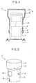
- Figure 3 is a perspective view showing a compressor with a sound insulation case in accordance with a preferred embodiment of the present invention
- Figure 4 is a sectional view showing a state that the sound insulation case is mounted in the compressor in accordance with the preferred embodiment of the present invention.
- the compressor of the present invention includes: a casing 2 with a certain closed space; a compressing unit 4 inserted in an upper portion of the casing 2 and performing a compressing operation on a fluid; a driving unit 6 inserted in a lower portion of the casing 2 and generating a driving force required for driving of the compressing unit 4; and a sound insulation case 8 mounted at an outer circumferential surface of an upper portion of the casing 2 and blocking a noise generated from the compressing unit 4 from transmitting outwardly.
- the casing 2 is formed in a closed cylindrical shape.
- a suction pipe 10 for sucking a fluid is connected at one side of the casing 2 and a discharge pipe 12 for discharging outwardly a compressed fluid is connected at the other side of the casing 2.
- a terminal box 14 for supplying power source to the driving unit 6 is mounted at an outer circumferential surface of the casing 2.
- the sound insulation case 8 includes: a noise insulation portion 16 coupled at an outer circumferential surface of an upper portion in which the compressing unit 4 of the casing 2 is inserted, with a space therebetween which can be hermetically sealed, and blocking a noise generated from the compressing unit 4; and a mounting portion 18 extended with a certain length downwardly from the noise insulation portion 16 and hermetically mounted at an outer circumferential surface of the casing 2.
- the noise insulation portion 16 includes: a cover 20 formed in a cylindrical shape with an upper side closed with a certain space in a circumferential direction at an outer circumferential surface of the upper portion of the casing 2 in which the compressing unit 4 is installed; and a noise absorbing material 22 attached at an inner circumferential surface of the cover 20 and absorbing a noise generated from the compressing unit 4.
- a discharge pipe through hole 26 is formed at one side of the noise insulation portion 16, into which the discharge pipe 12 for discharging a compressed fluid passes by being connected to the casing 2.
- the noise absorbing material 22 may be made of any material if the material has an excellent noise absorbing capacity.
- the mounting portion 18 is integrally extended downwardly from the cover 20 of the noise insulation portion and formed in a cylindrical shape covering with a certain length of the casing 2 so that the lower portion of the casing 2 can be exposed.
- First and second sealing portions 28 and 30 are protruded with a certain width in a circumferential direction from the upper and lower inner circumferential surface of the mounting portion and hermetically attached on the outer circumferential surface of the casing 2, and a locking band 32 is wound on the outer circumferential surface of the mounting portion 18 so as to adhere the first and second sealing portions 28 and 30 on the outer circumferential surface of the casing 2.
- An open cutting section 36 is formed cut with a certain length in an axial direction from the lower end of the mounting portion 8, to facilitate mounting of the sound insulation case 8 by being open when the sound insulation case 8 is inserted into the casing 2.
- a terminal box cabinet 38 is formed at one side of the mounting portion 8 to receive the terminal box 14, and a through hole 42 is formed into which the suction pipe 10 for sucking a fluid into the compressor passes.
- the locking band 32 is preferably made of an elastic material to allow an elastic force to facilitate attachment of the first and second sealing portions 28 and 30 on the outer circumferential surface of the casing 2.
- an elastic material besides the elastic material, various types can be adopted such as a clamp, a cable tie or a magic tape.
- the sound insulation case 8 is inserted from the upper side to the lower side of the casing 2. At this time, the sound insulation case 8 is inserted in a state that the open cutting section 36 of the mounting portion 18 is opened, so as to facilitate insertion of the sound insulation case 8.
- the suction pipe 10 passes the through hole 42 formed at the mounting portion 18, and the discharge pipe 12 passes the through hole 26 formed at the noise insulation portion 16.
- the locking band 32 is mounted on the outer circumferential surface of the mounting portion 18 so that the first and second sealing portions 28 and 30 of the mounting portion 18 can be hermetically attached on the outer circumferential surface of the casing 2.
- the mounting portion 18 is formed so long that the lower portion of the casing 2 is exposed with a certain length, so that heat generated when the compressor is driven can be discharged outwardly through the exposed portion of the casing 2.
- the compressor with the sound insulation case of the present invention has the following advantage.
Landscapes
- Engineering & Computer Science (AREA)
- Mechanical Engineering (AREA)
- General Engineering & Computer Science (AREA)
- Compressor (AREA)
- Applications Or Details Of Rotary Compressors (AREA)
- Rotary Pumps (AREA)
Abstract
Description
Claims (8)
- A compressor with a sound insulation case comprising:a casing with a closed space;a compressing unit inserted in an upper portion of the casing and performing a compressing operation;a driving unit inserted in a lower portion of the casing and generating a driving force required for the compressing operation of the compressor; anda sound insulation case mounted at an outer circumferential surface of an upper portion of the casing and preventing a noise generated from the compressing unit from leaking outwardly.
- The compressor of claim 1, wherein the sound insulation case comprises:a noise insulation portion mounted with a certain space at an outer circumferential surface of the upper portion of the casing in which the compressing unit is inserted, and blocking a noise generated from the compressing unit; anda mounting portion extended with a certain length downwardly of the noise insulation portion and hermetically mounted at an outer circumferential surface of the casing.
- The compressor of claim 2, wherein the noise insulation portion is disposed with a certain space at an outer circumferential surface of an upper portion of the casing and formed in a cylindrical shape with an upper side closed, and a sound absorbing material for absorbing a noise generated from the compressing unit is attached at an inner circumferential surface of the casing.
- The compressor of claim 2, wherein the mounting portion is integrally extended downwardly from the noise insulation portion, formed in a cylindrical shape and mounted at an outer circumferential surface of the casing, and includes a sealing portion formed at an inner circumferential surface thereof so as to be tightly attached on the outer circumferential surface of the casing hermetically and a locking band mounted at an outer circumferential surface thereof for attaching the sealing portion to be hermetically attached at the outer circumferential surface of the casing.
- The compressor of claim 4, wherein the mounting portion is formed to cover a portion of the casing so that a lower portion of the casing can be exposed for heat-sinking of the casing.
- The compressor of claim 4, wherein the sealing portion is formed in a circumferential direction at an upper and lower inner circumferential surface of the mounting portion and includes first and second sealing portions tightly attached on the outer circumferential surface of the casing.
- The compressor of claim 4, wherein the locking band is made of an elastic material with a certain elastic force.
- The compressor of claim 4, wherein the mounting portion includes: an open cutting section formed cut with a certain length in the upward direction from the lower end so that the sound insulation case can be easily inserted into the casing.
Applications Claiming Priority (2)
| Application Number | Priority Date | Filing Date | Title |
|---|---|---|---|
| KR2001083266 | 2001-12-22 | ||
| KR10-2001-0083266A KR100414121B1 (en) | 2001-12-22 | 2001-12-22 | Noise drcrease case for compressor |
Publications (3)
| Publication Number | Publication Date |
|---|---|
| EP1321674A2 true EP1321674A2 (en) | 2003-06-25 |
| EP1321674A3 EP1321674A3 (en) | 2003-08-20 |
| EP1321674B1 EP1321674B1 (en) | 2007-07-11 |
Family
ID=19717450
Family Applications (1)
| Application Number | Title | Priority Date | Filing Date |
|---|---|---|---|
| EP02022062A Expired - Lifetime EP1321674B1 (en) | 2001-12-22 | 2002-10-02 | Compressor with sound insulation case |
Country Status (5)
| Country | Link |
|---|---|
| EP (1) | EP1321674B1 (en) |
| JP (1) | JP2003201961A (en) |
| KR (1) | KR100414121B1 (en) |
| CN (1) | CN1228535C (en) |
| DE (1) | DE60221091T2 (en) |
Cited By (4)
| Publication number | Priority date | Publication date | Assignee | Title |
|---|---|---|---|---|
| EP1657443A1 (en) * | 2004-11-12 | 2006-05-17 | LG Electronics Inc. | Scroll compressor |
| EP1878921A4 (en) * | 2005-05-06 | 2013-11-27 | Sanden Corp | Closed type fluid machine |
| CN108468634A (en) * | 2018-05-23 | 2018-08-31 | 黄石东贝电器股份有限公司 | A kind of compressor housing, compressor and refrigerator |
| NL2040302A (en) * | 2024-05-05 | 2025-11-18 | Mobileye Vision Technologies Ltd | Apparatus, system, and method of vehicular imaging-device cleaning |
Families Citing this family (4)
| Publication number | Priority date | Publication date | Assignee | Title |
|---|---|---|---|---|
| JP2009125452A (en) * | 2007-11-27 | 2009-06-11 | Toshiba Corp | Washing and drying machine |
| CN105402121B (en) * | 2015-12-30 | 2017-11-10 | 郭辰 | A kind of super-silent oil-free vortex air compressor assembly |
| KR20230117917A (en) * | 2022-02-03 | 2023-08-10 | 삼성전자주식회사 | Sound shielding device for compressor in air conditioner |
| JP7715070B2 (en) * | 2022-03-30 | 2025-07-30 | 株式会社豊田自動織機 | Electric compressor |
Family Cites Families (12)
| Publication number | Priority date | Publication date | Assignee | Title |
|---|---|---|---|---|
| US4258821A (en) * | 1979-02-07 | 1981-03-31 | Wendt Gary R | Sound-absorbent blower cover |
| JPH0444869Y2 (en) * | 1986-10-01 | 1992-10-22 | ||
| JPH0267823U (en) * | 1988-07-27 | 1990-05-23 | ||
| JPH03160167A (en) * | 1989-11-15 | 1991-07-10 | Toshiba Corp | Closed type compressor |
| JP2928632B2 (en) * | 1990-11-30 | 1999-08-03 | 株式会社日立製作所 | Horizontal refrigerant compressor |
| JP3021961B2 (en) * | 1992-05-22 | 2000-03-15 | ダイキン工業株式会社 | Soundproof structure of compressor for refrigerator |
| US5997258A (en) * | 1994-05-31 | 1999-12-07 | Bristol Compressors, Inc. | Low noise refrigerant compressor having closed shells and sound absorbing spacers |
| KR200147708Y1 (en) * | 1994-09-29 | 1999-06-15 | 윤종용 | Hermetic compressor |
| JPH09303277A (en) * | 1996-05-10 | 1997-11-25 | Sanyo Electric Co Ltd | Scroll compressor |
| KR19990034294A (en) * | 1997-10-29 | 1999-05-15 | 전주범 | Noise reduction device of hermetic rotary compressor |
| JPH11294365A (en) * | 1998-04-09 | 1999-10-26 | Sharp Corp | Hermetic compressor |
| US6132183A (en) * | 1998-11-23 | 2000-10-17 | Carrier Corporation | Compressor mounting |
-
2001
- 2001-12-22 KR KR10-2001-0083266A patent/KR100414121B1/en not_active Expired - Fee Related
-
2002
- 2002-10-02 DE DE60221091T patent/DE60221091T2/en not_active Expired - Lifetime
- 2002-10-02 EP EP02022062A patent/EP1321674B1/en not_active Expired - Lifetime
- 2002-10-09 JP JP2002296184A patent/JP2003201961A/en active Pending
- 2002-12-20 CN CNB021578443A patent/CN1228535C/en not_active Expired - Fee Related
Cited By (4)
| Publication number | Priority date | Publication date | Assignee | Title |
|---|---|---|---|---|
| EP1657443A1 (en) * | 2004-11-12 | 2006-05-17 | LG Electronics Inc. | Scroll compressor |
| EP1878921A4 (en) * | 2005-05-06 | 2013-11-27 | Sanden Corp | Closed type fluid machine |
| CN108468634A (en) * | 2018-05-23 | 2018-08-31 | 黄石东贝电器股份有限公司 | A kind of compressor housing, compressor and refrigerator |
| NL2040302A (en) * | 2024-05-05 | 2025-11-18 | Mobileye Vision Technologies Ltd | Apparatus, system, and method of vehicular imaging-device cleaning |
Also Published As
| Publication number | Publication date |
|---|---|
| KR100414121B1 (en) | 2004-01-07 |
| CN1228535C (en) | 2005-11-23 |
| DE60221091T2 (en) | 2007-10-25 |
| CN1429991A (en) | 2003-07-16 |
| KR20030053197A (en) | 2003-06-28 |
| DE60221091D1 (en) | 2007-08-23 |
| EP1321674A3 (en) | 2003-08-20 |
| JP2003201961A (en) | 2003-07-18 |
| EP1321674B1 (en) | 2007-07-11 |
Similar Documents
| Publication | Publication Date | Title |
|---|---|---|
| EP2133571B1 (en) | Motor-driven compressor | |
| EP1291528B1 (en) | Scroll compressor and refrigerating system using ammonia group refrigerant | |
| KR102625341B1 (en) | Motor-driven compressor | |
| EP2307731A2 (en) | Compressor having terminal plug assembly | |
| KR101616624B1 (en) | Motor-driven compressor | |
| EP1321674B1 (en) | Compressor with sound insulation case | |
| JP2008232133A (en) | Electric compressor | |
| US7524172B2 (en) | Vibration reduction structure of reciprocating compressor | |
| US20030102729A1 (en) | Motor device for electrical compressor | |
| US20040115063A1 (en) | Scroll compressor | |
| US20050135940A1 (en) | Overheating protection apparatus of scroll compressor | |
| CN101346547B (en) | Electric compressor | |
| US20050135939A1 (en) | Scroll compressor having overheat preventing unit | |
| CN117501016A (en) | Hermetic compressor | |
| KR102868076B1 (en) | Electric compressor | |
| WO2006107015A1 (en) | Electric motor-driven compressor | |
| EP4138275A1 (en) | A cover for a housing of an electric machine | |
| US7165954B2 (en) | Apparatus for preventing vacuum state in scroll compressor | |
| US6912871B2 (en) | Structure for reducing refrigerant flow loss in compressor | |
| US6669456B2 (en) | Scroll compressor having reversion preventing device | |
| KR20190086898A (en) | Rotary compressor | |
| KR100408248B1 (en) | Sealing devise of muffler for hermetic rotary compressor | |
| JPH03160167A (en) | Closed type compressor | |
| KR20030042352A (en) | The apparatus for decreasing noise of compressor | |
| KR200162038Y1 (en) | Terminal of Hermetic Compressor |
Legal Events
| Date | Code | Title | Description |
|---|---|---|---|
| PUAI | Public reference made under article 153(3) epc to a published international application that has entered the european phase |
Free format text: ORIGINAL CODE: 0009012 |
|
| AK | Designated contracting states |
Designated state(s): AT BE BG CH CY CZ DE DK EE ES FI FR GB GR IE IT LI LU MC NL PT SE SK TR |
|
| AX | Request for extension of the european patent |
Extension state: AL LT LV MK RO SI |
|
| PUAL | Search report despatched |
Free format text: ORIGINAL CODE: 0009013 |
|
| AK | Designated contracting states |
Designated state(s): AT BE BG CH CY CZ DE DK EE ES FI FR GB GR IE IT LI LU MC NL PT SE SK TR |
|
| AX | Request for extension of the european patent |
Extension state: AL LT LV MK RO SI |
|
| 17P | Request for examination filed |
Effective date: 20040131 |
|
| AKX | Designation fees paid |
Designated state(s): DE FR GB IT |
|
| 17Q | First examination report despatched |
Effective date: 20040331 |
|
| GRAP | Despatch of communication of intention to grant a patent |
Free format text: ORIGINAL CODE: EPIDOSNIGR1 |
|
| GRAS | Grant fee paid |
Free format text: ORIGINAL CODE: EPIDOSNIGR3 |
|
| GRAA | (expected) grant |
Free format text: ORIGINAL CODE: 0009210 |
|
| AK | Designated contracting states |
Kind code of ref document: B1 Designated state(s): DE FR GB IT |
|
| REG | Reference to a national code |
Ref country code: GB Ref legal event code: FG4D |
|
| REF | Corresponds to: |
Ref document number: 60221091 Country of ref document: DE Date of ref document: 20070823 Kind code of ref document: P |
|
| ET | Fr: translation filed | ||
| PLBE | No opposition filed within time limit |
Free format text: ORIGINAL CODE: 0009261 |
|
| STAA | Information on the status of an ep patent application or granted ep patent |
Free format text: STATUS: NO OPPOSITION FILED WITHIN TIME LIMIT |
|
| 26N | No opposition filed |
Effective date: 20080414 |
|
| PGFP | Annual fee paid to national office [announced via postgrant information from national office to epo] |
Ref country code: DE Payment date: 20100929 Year of fee payment: 9 |
|
| PGFP | Annual fee paid to national office [announced via postgrant information from national office to epo] |
Ref country code: GB Payment date: 20110921 Year of fee payment: 10 Ref country code: FR Payment date: 20111004 Year of fee payment: 10 |
|
| PGFP | Annual fee paid to national office [announced via postgrant information from national office to epo] |
Ref country code: IT Payment date: 20110920 Year of fee payment: 10 |
|
| GBPC | Gb: european patent ceased through non-payment of renewal fee |
Effective date: 20121002 |
|
| REG | Reference to a national code |
Ref country code: FR Ref legal event code: ST Effective date: 20130628 |
|
| PG25 | Lapsed in a contracting state [announced via postgrant information from national office to epo] |
Ref country code: DE Free format text: LAPSE BECAUSE OF NON-PAYMENT OF DUE FEES Effective date: 20130501 Ref country code: GB Free format text: LAPSE BECAUSE OF NON-PAYMENT OF DUE FEES Effective date: 20121002 |
|
| REG | Reference to a national code |
Ref country code: DE Ref legal event code: R119 Ref document number: 60221091 Country of ref document: DE Effective date: 20130501 |
|
| PG25 | Lapsed in a contracting state [announced via postgrant information from national office to epo] |
Ref country code: FR Free format text: LAPSE BECAUSE OF NON-PAYMENT OF DUE FEES Effective date: 20121031 Ref country code: IT Free format text: LAPSE BECAUSE OF NON-PAYMENT OF DUE FEES Effective date: 20121002 |