EP1321628A2 - Airfoil for a turbine nozzle of a gas turbine engine and method of making same - Google Patents
Airfoil for a turbine nozzle of a gas turbine engine and method of making same Download PDFInfo
- Publication number
- EP1321628A2 EP1321628A2 EP02258505A EP02258505A EP1321628A2 EP 1321628 A2 EP1321628 A2 EP 1321628A2 EP 02258505 A EP02258505 A EP 02258505A EP 02258505 A EP02258505 A EP 02258505A EP 1321628 A2 EP1321628 A2 EP 1321628A2
- Authority
- EP
- European Patent Office
- Prior art keywords
- airfoil
- slot
- side wall
- cooling
- trailing edge
- Prior art date
- Legal status (The legal status is an assumption and is not a legal conclusion. Google has not performed a legal analysis and makes no representation as to the accuracy of the status listed.)
- Granted
Links
- 238000004519 manufacturing process Methods 0.000 title description 5
- 238000001816 cooling Methods 0.000 claims abstract description 71
- 230000007423 decrease Effects 0.000 claims description 2
- 239000011162 core material Substances 0.000 description 23
- 238000005266 casting Methods 0.000 description 7
- 239000000919 ceramic Substances 0.000 description 7
- 239000007789 gas Substances 0.000 description 6
- 230000035882 stress Effects 0.000 description 6
- 238000000034 method Methods 0.000 description 5
- 238000013461 design Methods 0.000 description 3
- 239000000567 combustion gas Substances 0.000 description 2
- 239000002184 metal Substances 0.000 description 2
- 230000006978 adaptation Effects 0.000 description 1
- 230000002411 adverse Effects 0.000 description 1
- 239000000956 alloy Substances 0.000 description 1
- 229910045601 alloy Inorganic materials 0.000 description 1
- 229910010293 ceramic material Inorganic materials 0.000 description 1
- 238000004891 communication Methods 0.000 description 1
- 238000005336 cracking Methods 0.000 description 1
- 230000008030 elimination Effects 0.000 description 1
- 238000003379 elimination reaction Methods 0.000 description 1
- 238000007730 finishing process Methods 0.000 description 1
- 230000013011 mating Effects 0.000 description 1
- 238000005058 metal casting Methods 0.000 description 1
- 238000003801 milling Methods 0.000 description 1
- 238000012986 modification Methods 0.000 description 1
- 230000004048 modification Effects 0.000 description 1
- 238000013021 overheating Methods 0.000 description 1
- 230000002028 premature Effects 0.000 description 1
- 239000002002 slurry Substances 0.000 description 1
- 230000008646 thermal stress Effects 0.000 description 1
Images


Classifications
-
- F—MECHANICAL ENGINEERING; LIGHTING; HEATING; WEAPONS; BLASTING
- F01—MACHINES OR ENGINES IN GENERAL; ENGINE PLANTS IN GENERAL; STEAM ENGINES
- F01D—NON-POSITIVE DISPLACEMENT MACHINES OR ENGINES, e.g. STEAM TURBINES
- F01D5/00—Blades; Blade-carrying members; Heating, heat-insulating, cooling or antivibration means on the blades or the members
- F01D5/12—Blades
- F01D5/14—Form or construction
- F01D5/18—Hollow blades, i.e. blades with cooling or heating channels or cavities; Heating, heat-insulating or cooling means on blades
- F01D5/187—Convection cooling
-
- F—MECHANICAL ENGINEERING; LIGHTING; HEATING; WEAPONS; BLASTING
- F05—INDEXING SCHEMES RELATING TO ENGINES OR PUMPS IN VARIOUS SUBCLASSES OF CLASSES F01-F04
- F05D—INDEXING SCHEME FOR ASPECTS RELATING TO NON-POSITIVE-DISPLACEMENT MACHINES OR ENGINES, GAS-TURBINES OR JET-PROPULSION PLANTS
- F05D2230/00—Manufacture
- F05D2230/20—Manufacture essentially without removing material
- F05D2230/21—Manufacture essentially without removing material by casting
-
- Y—GENERAL TAGGING OF NEW TECHNOLOGICAL DEVELOPMENTS; GENERAL TAGGING OF CROSS-SECTIONAL TECHNOLOGIES SPANNING OVER SEVERAL SECTIONS OF THE IPC; TECHNICAL SUBJECTS COVERED BY FORMER USPC CROSS-REFERENCE ART COLLECTIONS [XRACs] AND DIGESTS
- Y10—TECHNICAL SUBJECTS COVERED BY FORMER USPC
- Y10T—TECHNICAL SUBJECTS COVERED BY FORMER US CLASSIFICATION
- Y10T29/00—Metal working
- Y10T29/49—Method of mechanical manufacture
- Y10T29/49316—Impeller making
- Y10T29/49336—Blade making
- Y10T29/49339—Hollow blade
- Y10T29/49341—Hollow blade with cooling passage
Definitions
- a nozzle segment for the high pressure turbine of a gas turbine engine typically includes a pair of hollow airfoils with integral inner and outer flowpath bands. These pieces are cast separately, partially machined, brazed together, and subsequently finish machined to form the nozzle segment.
- the hollow airfoil is fed internally with cooling air which then flows through trailing edge slots that exit the aft cavity of the airfoil and discharges through openings in the trailing edge of the airfoil. This cooling air then performs convection cooling as it passes along the trailing edge slot within the airfoil. When such air discharges to the flowpath through the openings in the airfoil trailing edge, it provides film cooling for the airfoil trailing edge.
- Turbine airfoils with trailing edge cooling slots inherently have a step between the slot and the rib between the slots. It has been found that the step in the cooling slot closest to the nozzle bands at the inner and outer airfoil/flowpath intersection causes a large stress concentration with high thermal stresses present, which can then result in trail edge axial cracks. The cracks ultimately propagate through the airfoil section and lead to premature failure of the turbine nozzles. The cooling slot itself cannot be removed since overheating of the trailing edge of the airfoil would result. Moreover, the step is difficult to grind smooth because of its proximity to the airfoil/band junction.
- the hollow airfoil cavities and trailing edge cooling slots are formed during a casting process by ceramic core which is produced separately and combined with a wax pattern prior to casting.
- corner fillets for the trailing edge slot are created by the ceramic core and minimized in order to reduce slot blockage and maintain cooling flow area.
- the ceramic core is subjected to auto-finishing to remove unwanted core material around the core die splitline. It has been found that this process often removes some, if not all, of the external corner fillet on the core and results in a sharp internal corner in the finished casting. This corner acts as a stress concentration and can initiate cracking of the airfoil trailing edge.
- an airfoil for a turbine nozzle assembly of a gas turbine engine is disclosed as including an outer side wall, an inner side wall, a leading edge extending from the outer side wall to the inner side wall, a trailing edge extending from the outer side wall to the inner side wall, a concave surface extending from the leading edge to the trailing edge on a pressure side of the airfoil, a convex surface extending from the leading edge to the trailing edge on a suction side of the airfoil, an outer cooling slot, an inner cooling slot, and at least one middle cooling slot formed in the concave side of the airfoil adjacent the trailing edge.
- Each of the cooling slots also includes a recessed wall, an inner slot side wall, an outer slot side wall, an inner corner fillet located between the inner slot side wall and the recessed wall, and an outer corner fillet located between the outer slot side wall and the recessed wall, wherein one of the inner and outer corner fillets of at least one of the inner and outer cooling slots forms a variable contour from an opening in the concave surface to an exit plane of the trailing edge cooling slots. More specifically, the corner fillet forming the variable contour is radiused in a first plane substantially perpendicular to the slot exit plane from the opening to the exit plane.
- the airfoil also includes a junction between the corner fillet forming the variable contour and an end portion of the airfoil, wherein the junction is radiused in a second plane substantially perpendicular to the slot exit plane from the opening to the exit plane.
- an airfoil core for a turbine airfoil is disclosed as including a wedge channel for forming a hollow portion of an airfoil and a plurality of fingers extending from the wedge channel, wherein at least one of the fingers located at an end is configured to have a distal portion with a predetermined radius from a first side wall to a second side wall.
- the distal portion of the finger is radiused in a first plane substantially perpendicular to an axis through the finger and radiused in a second plane substantially parallel to the axis through the finger.
- a method of fabricating an airfoil of a turbine nozzle including the steps of inserting a mold within a die and injecting a slurry into the die.
- An airfoil is formed that includes an outer side wall, an inner side wall, a leading edge extending from the outer side wall to the inner side wall, a trailing edge extending from the outer side wall to the inner side wall, a concave surface extending from the leading edge to the trailing edge on a pressure side of the airfoil, a convex surface extending from the leading edge to the trailing edge on a suction side of the airfoil, and a plurality of cooling slots formed in the concave side of the airfoil adjacent the trailing edge, each of the cooling slots further including a recessed wall and a pair of slot side walls, and a variable contour for a corner fillet between the recessed wall and one of the slot side walls of a cooling slot adjacent at least one of the inner and outer
- the corner fillet is formed with a radius in a first plane substantially perpendicular to the slot exit plane that gradually increases from a minimum radius at the opening to a maximum radius at the slot exit plane.
- the method also includes the step of forming a junction between the corner fillet and an end portion of the airfoil, wherein the junction is radiused in a second plane substantially perpendicular to the slot exit plane from the opening to the exit plane.
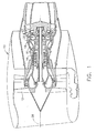
- FIG. 1 depicts an exemplary turbofan gas turbine engine 10 having in serial flow communication a conventional fan 12, a high pressure compressor 14, and a combustor 16.
- Combustor 16 conventionally generates combustion gases that are discharged therefrom through a high pressure turbine nozzle assembly 18, from which the combustion gases are channeled to a conventional high pressure turbine 20 and, in turn, to a conventional low pressure turbine 22.
- High pressure turbine 20 drives high pressure compressor 14 through a suitable shaft 24, while low pressure turbine 22 drives fan 12 through another suitable shaft 26, all disposed coaxially about a longitudinal or axial centerline axis 28.
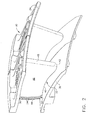
- turbine nozzle 18 preferably includes a plurality of circumferentially adjoining nozzle segments 30 to collectively form a complete 360° assembly.
- Each nozzle segment 30 preferably has two or more circumferentially spaced airfoils 32 which are connected to an arcuate radially outer band 34 and an arcuate radially inner band 36.
- each airfoil 32 includes an outer side wall 38 whose surface lies adjacent to outer band 34, an inner side wall 40 whose surface lies adjacent to inner band 36, a leading edge 42 extending from outer side wall 38 to inner side wall 40, a trailing edge 44 extending from outer side wall 38 to inner side wall 40, a concave surface 46 extending from leading edge 42 to trailing edge 44 on a pressure side of airfoil 32, and a convex surface 48 extending from leading edge 42 to trailing edge 44 on a suction side of airfoil 32.
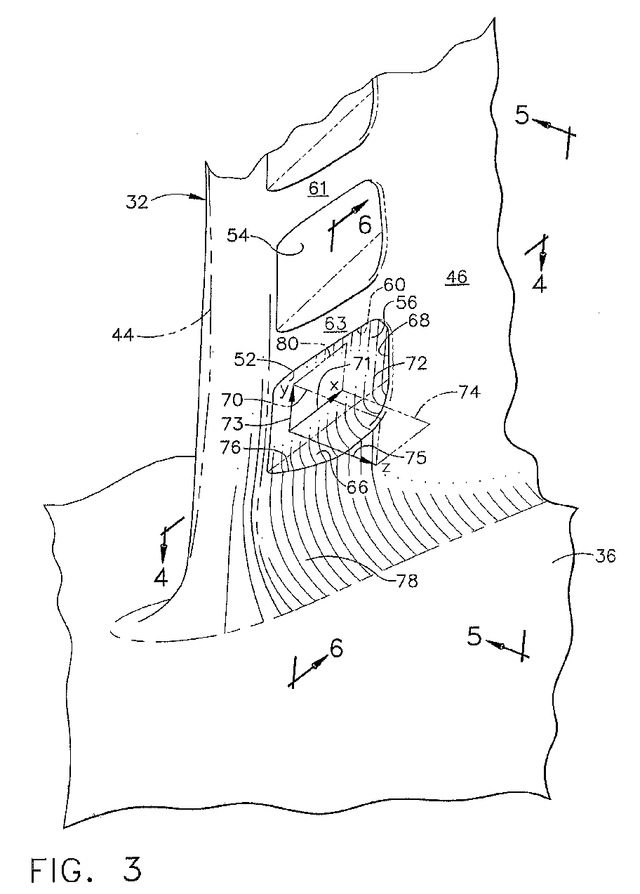
- airfoils 32 further include an outer cooling slot 50 located adjacent outer band 34, an inner cooling slot 52 located adjacent inner band 36, and at least one middle cooling slot 54 located between outer and inner cooling slots 50 and 52, respectively.
- each of cooling slots 50, 52 and 54 is formed by a recessed wall 56, an inner slot side wall 58, an outer slot side wall 60, an inner corner fillet 62 located between inner slot side wall 58 and recessed wall 56, and an outer corner fillet 64 located between outer slot side wall 60 and recessed wall 56.
- the inner and outer slot walls 58 and 60 are generally provided by adjacent ribs 61 interposed between each cooling slot, but it will be seen that a rib 63 is used to provide outer slot side wall 60 for inner cooling slot 52 and an inner portion 78 of airfoil 32 (discussed in greater detail hereinafter) provides inner slot side wall 58 thereof.
- At least one of inner corner fillet 62 for inner cooling slot 52 and outer corner fillet 64 for outer cooling slot 50 form a variable contour (as designated by surface 66 in Fig. 3) from an opening 68 in concave surface 46 (known in the art as the breakout) to an exit plane 70 which extends substantially perpendicular to cooling slots 50, 52 and 54.
- exit plane 70 is defined as the extending in the y-z plane thereof.
- the present invention can be, and preferably is, applied in mirror image to outer corner fillet 64 for outer cooling slot 50.
- surface 66 (which may also be considered inner slot side wall 58 for inner cooling slot 52) is radiused in a first plane 74 (defined as extending in the x-z plane) which extends substantially perpendicular to slot exit plane 70 from opening 68 to slot exit plane 70.
- first plane 74 defined as extending in the x-z plane
- the radius of inner corner fillet 62 forming the variable contour gradually increases from a minimum radius R min at opening 68 to a maximum radius R max at slot exit plane 70. This is done in order to maintain the slot area, footprint and cooling characteristics for inner cooling slot 52.
- airfoil 32 includes a junction 76 between inner corner fillet 62 and an inner portion 78 of concave surface 46, wherein junction 76 is radiused in a second plane 80 (defined as extending in the x-y plane) which extends substantially perpendicular to slot exit plane 70 (and first plane 74) from opening 68 to slot exit plane 72.
- a second plane 80 defined as extending in the x-y plane
- an angle ⁇ between inner corner fillet 62 and inner portion 78 of airfoil 32 is established at junction 76, where such angel ⁇ gradually decreases from a maximum angle ⁇ max at opening 68 to a minimum angle ⁇ min at slot exit plane 72.
- maximum angle ⁇ max be approximately 65°-85° and minimum angle ⁇ min be approximately 0°-10°.
- angle ⁇ is approximately 45° at the approximate mid-point between opening 68 and slot exit plane 70 shown in Fig. 6.
- inner slot side wall 58 and recessed wall 56 of inner cooling slot 52 preferably form a continuous curve having a predetermined radius from opening 68 in concave surface 46 to slot exit plane 70 (best seen in Fig. 6).
- outer slot side wall 60 and recessed wall 56 will preferably form a continuous curve having a predetermined radius from opening 68 in concave surface 46 to slot exit plane 70.
- airfoil core 100 is utilized to form the interior hollow portions and trailing edge cooling slots 50, 52 and 54 of airfoil 32.
- airfoil core 100 includes a wedge channel 104, an outer finger 105, a plurality of middle fingers 106, and an inner finger 108 extending from wedge channel 104.
- inner finger 108 is utilized to form inner cooling slot 52 of airfoil 32
- outer finger 105 forms outer cooling slot 50
- middle fingers 106 form middle cooling slots 54.
- inner finger 108 is configured to have a stem portion 109 connected to wedge channel 104 and a distal portion 110 which has a predetermined radius from a first side wall 112 to a second side wall 114 when viewed in section (see Figs. 6-8).
- a continuous curve is established by recessed wall 56 and inner slot side wall 58 of inner cooling slot 52 as described hereinabove.
- a continuous curve is established by recessed wall 56 and outer slot side wall 60 for outer cooling slot 50 in airfoil 32 since distal portion 115 of outer finger 105 preferably has a predetermined radius from a first side wall 117 to a second side wall 119 (see Fig. 8).
- distal portion 110 of inner finger 108 is radiused in a first plane 116 (corresponding to first plane 74) substantially perpendicular to an axis 118 through inner finger 108, as well as a second plane 120 (corresponding to second plane 80) substantially parallel to axis 118.
- first plane 116 corresponding to first plane 74
- second plane 120 corresponding to second plane 80
- airfoil core 100 is discussed with respect to inner finger 108, it will be appreciated that a mirror image thereof is preferably utilized for outer finger 105 to form the preferred configuration of outer cooling slot 50 in airfoil 32.
- Airfoil core 100 results in "flash," where ceramic material escapes between two mating pieces of the die. Airfoil core 100 is then preferably finished using a small computer controlled milling machine to remove the flash. As demonstrated by dashed line 122 in Fig. 6, this finishing process can also remove a portion of the radius for finger side walls that eventually form inner and outer corner fillets 62 and 64, which has created sharp corners in previous designs.
- airfoil core 100 is held within a die so that a wax encapsulates it.
- a final wax pattern is produced which is a replica of the metal casting for airfoil 32, with airfoil core 100 taking the place of cavities formed in the finished part.
- the wax pattern is dipped in a ceramic solution and dried a number of times to build up layers which form a strong shell mold. The mold is then heated to melt out the wax and cure the ceramic so that airfoil core 100 remains within the shell to form the cavities of airfoil 32 when the mold is filled with molten metal.
- a molten alloy is poured into the mold, taking up the form left by the wax, with airfoil core 100 preventing the metal from entering areas that are to be cavities in the finished casting and creating the internal features. Finally, the ceramic shell is broken off the casting and the internal ceramic core 100 is leached out using a dissolving solution.
- the final casting of airfoil 32 thus has the external form of the wax pattern and the internal features of airfoil core 100, which preferably includes inner corner fillet 62 of inner cooling slot 52 and outer corner fillet 64 of outer cooling slot 50 as described above.
Landscapes
- Engineering & Computer Science (AREA)
- Mechanical Engineering (AREA)
- General Engineering & Computer Science (AREA)
- Turbine Rotor Nozzle Sealing (AREA)
Abstract
Description
Claims (10)
- An airfoil (32), comprising:wherein one of said inner and outer corner fillets (62,64) for at least one of said inner and outer cooling slots (52,50) forms a variable contour (66) from an opening (68) in said concave surface (46) to an exit plane (70) of said trailing edge cooling slots (50,52,54).(a) an outer side wall (38);(b) an inner side wall (40);(c) a leading edge (42) extending from said outer side wall (38) to said inner side wall (40);(d) a trailing edge (44) extending from said outer side wall (38) to said inner side wall (40);(e) a concave surface (46) extending from said leading edge (42) to said trailing edge (44) on a pressure side of said airfoil (32);(f) a convex surface (48) extending from said leading edge (42) to said trailing edge (44) on a suction side of said airfoil (32);(g) an outer cooling slot (50), an inner cooling slot (52), and at least one middle cooling slot (54) formed in said concave side (46) of said airfoil (32) adjacent said trailing edge (44), each of said cooling slots (50,52,54) further including:(1) a recessed wall (56);(2) an inner slot side wall (58);(3) an outer slot side wall (60);(4) an inner corner fillet (62) located between said inner slot side wall (58) and said recessed wall (56); and,(5) an outer corner fillet (64) located between said outer slot side wall (60) and said recessed wall (56);
- The airfoil of claim 1, wherein said corner fillet (62/64) forming a variable contour (66) is radiused in a first plane (74) substantially perpendicular to said slot exit plane (70) from said opening (68) to said exit plane (70).
- The airfoil claim 2, wherein said radius of said corner fillet (62/64) forming a variable contour (66) gradually increases from a minimum radius at said opening (68) to a maximum radius at said exit plane (70).
- The airfoil of claim 1, said airfoil (32) including a junction (76) between said corner fillet (62/64) forming a variable contour (66) and an end portion (78) of said airfoil (32), wherein said junction (76) is radiused in a second plane (80) substantially perpendicular to said slot exit plane (70) from said opening (68) to said exit plane (70).
- The airfoil of claim 4, wherein an angle (0) between said corner fillet (62/64) and said end portion (78) of said airfoil (32) at said junction (76) gradually decreases from a maximum angle at said opening (68) to a minimum angle at said exit plane (70).
- The airfoil of claim 1, wherein said corner fillet (62/64) forming a variable contour (66) is said outer corner fillet (64) in said outer cooling slot (50).
- The airfoil of claim 1, wherein said corner fillet (62/64) forming a variable contour (66) is said inner corner fillet (62) in said inner cooling slot (52).
- The airfoil of claim 6, wherein said outer side wall (60) and said recessed wall (56) of said outer cooling slot (50) form a continuous curve having a predetermined radius from an opening (68) in said concave surface (46) to said slot exit plane (70).
- The airfoil of claim 7, wherein said inner side wall (58) and said recessed wall (56) of said inner cooling slot (52) form a continuous curve having a predetermined radius from an opening (68) in said concave surface (46) to said slot exit plane (70).
- A turbine nozzle for a gas turbine engine, including an airfoil (32) in accordance with any one of claims 1 to 9.
Applications Claiming Priority (2)
| Application Number | Priority Date | Filing Date | Title |
|---|---|---|---|
| US10/015,313 US6612811B2 (en) | 2001-12-12 | 2001-12-12 | Airfoil for a turbine nozzle of a gas turbine engine and method of making same |
| US15313 | 2001-12-12 |
Publications (3)
| Publication Number | Publication Date |
|---|---|
| EP1321628A2 true EP1321628A2 (en) | 2003-06-25 |
| EP1321628A3 EP1321628A3 (en) | 2004-05-26 |
| EP1321628B1 EP1321628B1 (en) | 2007-08-08 |
Family
ID=21770699
Family Applications (1)
| Application Number | Title | Priority Date | Filing Date |
|---|---|---|---|
| EP02258505A Expired - Lifetime EP1321628B1 (en) | 2001-12-12 | 2002-12-10 | Airfoil for a turbine nozzle of a gas turbine engine and method of making same |
Country Status (4)
| Country | Link |
|---|---|
| US (1) | US6612811B2 (en) |
| EP (1) | EP1321628B1 (en) |
| JP (1) | JP4374184B2 (en) |
| DE (1) | DE60221628T2 (en) |
Cited By (8)
| Publication number | Priority date | Publication date | Assignee | Title |
|---|---|---|---|---|
| EP1726781A1 (en) * | 2005-04-01 | 2006-11-29 | The General Electric Company | Turbine airfoil with tapered trailing edge ribs |
| FR2924156A1 (en) * | 2007-11-26 | 2009-05-29 | Snecma Sa | Blade for use in high pressure turbine of e.g. turboprop engine, has ribs with ends formed closer to trailing edge in zone, and small ribs arranged closer to platform, where surfaces are connected at level of trailing and leading edges |
| US7934906B2 (en) | 2007-11-14 | 2011-05-03 | Siemens Energy, Inc. | Turbine blade tip cooling system |
| FR2983420A1 (en) * | 2011-12-06 | 2013-06-07 | Michael Appleby | SYSTEMS, DEVICES AND / OR METHODS FOR FORMING HOLES |
| CN103195495A (en) * | 2012-01-05 | 2013-07-10 | 通用电气公司 | Slotted turbine airfoil |
| EP2636466A1 (en) * | 2012-03-07 | 2013-09-11 | Siemens Aktiengesellschaft | A core for casting a hollow component |
| EP2286938A3 (en) * | 2009-07-27 | 2015-02-25 | United Technologies Corporation | Refractory metal core for integrally cast exit trench |
| CN105689690A (en) * | 2014-10-31 | 2016-06-22 | 联合工艺公司 | Additively manufactured casting articles for manufacturing gas turbine engine parts |
Families Citing this family (24)
| Publication number | Priority date | Publication date | Assignee | Title |
|---|---|---|---|---|
| GB2391046B (en) * | 2002-07-18 | 2007-02-14 | Rolls Royce Plc | Aerofoil |
| DE10346366A1 (en) * | 2003-09-29 | 2005-04-28 | Rolls Royce Deutschland | Turbine blade for an aircraft engine and casting mold for the production thereof |
| FR2864990B1 (en) * | 2004-01-14 | 2008-02-22 | Snecma Moteurs | IMPROVEMENTS IN THE HIGH-PRESSURE TURBINE AIR COOLING AIR EXHAUST DUCTING SLOTS |
| US7217094B2 (en) * | 2004-10-18 | 2007-05-15 | United Technologies Corporation | Airfoil with large fillet and micro-circuit cooling |
| US7575414B2 (en) * | 2005-04-01 | 2009-08-18 | General Electric Company | Turbine nozzle with trailing edge convection and film cooling |
| US7097540B1 (en) | 2005-05-26 | 2006-08-29 | General Electric Company | Methods and apparatus for machining formed parts to obtain a desired profile |
| US7360988B2 (en) * | 2005-12-08 | 2008-04-22 | General Electric Company | Methods and apparatus for assembling turbine engines |
| US7387492B2 (en) * | 2005-12-20 | 2008-06-17 | General Electric Company | Methods and apparatus for cooling turbine blade trailing edges |
| US20100034662A1 (en) * | 2006-12-26 | 2010-02-11 | General Electric Company | Cooled airfoil and method for making an airfoil having reduced trail edge slot flow |
| US9315663B2 (en) | 2008-09-26 | 2016-04-19 | Mikro Systems, Inc. | Systems, devices, and/or methods for manufacturing castings |
| US8632297B2 (en) | 2010-09-29 | 2014-01-21 | General Electric Company | Turbine airfoil and method for cooling a turbine airfoil |
| EP2450123A1 (en) * | 2010-11-03 | 2012-05-09 | Siemens Aktiengesellschaft | Method for manufacturinf a core forming tool |
| US9175569B2 (en) | 2012-03-30 | 2015-11-03 | General Electric Company | Turbine airfoil trailing edge cooling slots |
| US9017026B2 (en) | 2012-04-03 | 2015-04-28 | General Electric Company | Turbine airfoil trailing edge cooling slots |
| US9145773B2 (en) | 2012-05-09 | 2015-09-29 | General Electric Company | Asymmetrically shaped trailing edge cooling holes |
| US20130302179A1 (en) * | 2012-05-09 | 2013-11-14 | Robert Frederick Bergholz, JR. | Turbine airfoil trailing edge cooling hole plug and slot |
| US9879546B2 (en) * | 2012-06-21 | 2018-01-30 | United Technologies Corporation | Airfoil cooling circuits |
| US9003657B2 (en) * | 2012-12-18 | 2015-04-14 | General Electric Company | Components with porous metal cooling and methods of manufacture |
| US10352180B2 (en) | 2013-10-23 | 2019-07-16 | General Electric Company | Gas turbine nozzle trailing edge fillet |
| MX392790B (en) | 2015-04-08 | 2025-03-24 | Horton Inc | FAN BLADE SURFACE CHARACTERISTICS. |
| US20170306775A1 (en) * | 2016-04-21 | 2017-10-26 | General Electric Company | Article, component, and method of making a component |
| DE102020207646A1 (en) * | 2020-06-22 | 2021-12-23 | Siemens Aktiengesellschaft | Turbine blade and method for processing such |
| US12158083B2 (en) * | 2021-11-18 | 2024-12-03 | Rtx Corporation | Airfoil with axial cooling slot having diverging ramp |
| US11998974B2 (en) | 2022-08-30 | 2024-06-04 | General Electric Company | Casting core for a cast engine component |
Family Cites Families (13)
| Publication number | Priority date | Publication date | Assignee | Title |
|---|---|---|---|---|
| US4684323A (en) * | 1985-12-23 | 1987-08-04 | United Technologies Corporation | Film cooling passages with curved corners |
| US5700132A (en) * | 1991-12-17 | 1997-12-23 | General Electric Company | Turbine blade having opposing wall turbulators |
| US5368441A (en) * | 1992-11-24 | 1994-11-29 | United Technologies Corporation | Turbine airfoil including diffusing trailing edge pedestals |
| US5382133A (en) * | 1993-10-15 | 1995-01-17 | United Technologies Corporation | High coverage shaped diffuser film hole for thin walls |
| US5599166A (en) * | 1994-11-01 | 1997-02-04 | United Technologies Corporation | Core for fabrication of gas turbine engine airfoils |
| US5662160A (en) | 1995-10-12 | 1997-09-02 | General Electric Co. | Turbine nozzle and related casting method for optimal fillet wall thickness control |
| US5609779A (en) * | 1996-05-15 | 1997-03-11 | General Electric Company | Laser drilling of non-circular apertures |
| US6004100A (en) * | 1997-11-13 | 1999-12-21 | United Technologies Corporation | Trailing edge cooling apparatus for a gas turbine airfoil |
| FR2782118B1 (en) * | 1998-08-05 | 2000-09-15 | Snecma | COOLED TURBINE BLADE WITH LEADING EDGE |
| US6062817A (en) | 1998-11-06 | 2000-05-16 | General Electric Company | Apparatus and methods for cooling slot step elimination |
| US6095750A (en) | 1998-12-21 | 2000-08-01 | General Electric Company | Turbine nozzle assembly |
| US6126400A (en) | 1999-02-01 | 2000-10-03 | General Electric Company | Thermal barrier coating wrap for turbine airfoil |
| US6183192B1 (en) | 1999-03-22 | 2001-02-06 | General Electric Company | Durable turbine nozzle |
-
2001
- 2001-12-12 US US10/015,313 patent/US6612811B2/en not_active Expired - Lifetime
-
2002
- 2002-12-10 EP EP02258505A patent/EP1321628B1/en not_active Expired - Lifetime
- 2002-12-10 DE DE60221628T patent/DE60221628T2/en not_active Expired - Lifetime
- 2002-12-11 JP JP2002358882A patent/JP4374184B2/en not_active Expired - Fee Related
Cited By (12)
| Publication number | Priority date | Publication date | Assignee | Title |
|---|---|---|---|---|
| EP1726781A1 (en) * | 2005-04-01 | 2006-11-29 | The General Electric Company | Turbine airfoil with tapered trailing edge ribs |
| CN1840859B (en) * | 2005-04-01 | 2012-08-08 | 通用电气公司 | Turbine airfoil with trailing edge convection |
| US7934906B2 (en) | 2007-11-14 | 2011-05-03 | Siemens Energy, Inc. | Turbine blade tip cooling system |
| FR2924156A1 (en) * | 2007-11-26 | 2009-05-29 | Snecma Sa | Blade for use in high pressure turbine of e.g. turboprop engine, has ribs with ends formed closer to trailing edge in zone, and small ribs arranged closer to platform, where surfaces are connected at level of trailing and leading edges |
| EP2286938A3 (en) * | 2009-07-27 | 2015-02-25 | United Technologies Corporation | Refractory metal core for integrally cast exit trench |
| FR2983420A1 (en) * | 2011-12-06 | 2013-06-07 | Michael Appleby | SYSTEMS, DEVICES AND / OR METHODS FOR FORMING HOLES |
| CN103195495A (en) * | 2012-01-05 | 2013-07-10 | 通用电气公司 | Slotted turbine airfoil |
| CN103195495B (en) * | 2012-01-05 | 2016-03-23 | 通用电气公司 | The turbine airfoil of trough of belt |
| EP2636466A1 (en) * | 2012-03-07 | 2013-09-11 | Siemens Aktiengesellschaft | A core for casting a hollow component |
| WO2013131594A1 (en) * | 2012-03-07 | 2013-09-12 | Siemens Aktiengesellschaft | A core for casting a hollow component |
| CN105689690A (en) * | 2014-10-31 | 2016-06-22 | 联合工艺公司 | Additively manufactured casting articles for manufacturing gas turbine engine parts |
| CN105689690B (en) * | 2014-10-31 | 2019-06-04 | 联合工艺公司 | Additively manufactured castings for the manufacture of gas turbine engine parts |
Also Published As
| Publication number | Publication date |
|---|---|
| JP2003201805A (en) | 2003-07-18 |
| US6612811B2 (en) | 2003-09-02 |
| DE60221628D1 (en) | 2007-09-20 |
| US20030108423A1 (en) | 2003-06-12 |
| EP1321628A3 (en) | 2004-05-26 |
| DE60221628T2 (en) | 2008-05-21 |
| EP1321628B1 (en) | 2007-08-08 |
| JP4374184B2 (en) | 2009-12-02 |
Similar Documents
| Publication | Publication Date | Title |
|---|---|---|
| US6612811B2 (en) | Airfoil for a turbine nozzle of a gas turbine engine and method of making same | |
| JP7455074B2 (en) | Ceramic core for multi-cavity turbine blades | |
| US7841083B2 (en) | Method of manufacturing a turbomachine component that includes cooling air discharge orifices | |
| EP1930097B1 (en) | A core for use in a casting mould | |
| US4417381A (en) | Method of making gas turbine engine blades | |
| US6257831B1 (en) | Cast airfoil structure with openings which do not require plugging | |
| US4422229A (en) | Method of making an airfoil member for a gas turbine engine | |
| EP2554294B1 (en) | Hybrid core assembly | |
| EP2071126B1 (en) | Turbine blades and methods of manufacturing | |
| US6915840B2 (en) | Methods and apparatus for fabricating turbine engine airfoils | |
| EP1279796B1 (en) | Selective step turbine nozzle and method of making such nozzle | |
| US6062817A (en) | Apparatus and methods for cooling slot step elimination | |
| JP4482273B2 (en) | Method and apparatus for cooling a gas turbine nozzle | |
| JP2008151129A (en) | Turbine engine component and its manufacturing method | |
| US11220918B2 (en) | Gas turbine component with cooling aperture having shaped inlet and method of forming the same | |
| CN106457363A (en) | Turbine blade investment casting using film hole protrusions for integral wall thickness control | |
| JP2000199402A (en) | Turbine blades with chamfers with truncated tips | |
| US6932570B2 (en) | Methods and apparatus for extending gas turbine engine airfoils useful life | |
| US6485262B1 (en) | Methods and apparatus for extending gas turbine engine airfoils useful life | |
| JP3927628B2 (en) | Turbine nozzle and its investment casting method | |
| KR19980024573A (en) | Airfoil and stator wings | |
| US20170081967A1 (en) | Casting of thin wall hollow airfoil sections | |
| EP4259376B1 (en) | Method of producing a high-pressure turbine blade comprising a cavity under a squealer tip | |
| CN105705265A (en) | Investment casting method for gas turbine engine vane segment | |
| US20210121945A1 (en) | Cast-in film cooling hole structures |
Legal Events
| Date | Code | Title | Description |
|---|---|---|---|
| PUAI | Public reference made under article 153(3) epc to a published international application that has entered the european phase |
Free format text: ORIGINAL CODE: 0009012 |
|
| AK | Designated contracting states |
Designated state(s): AT BE BG CH CY CZ DE DK EE ES FI FR GB GR IE IT LI LU MC NL PT SE SI SK TR |
|
| AX | Request for extension of the european patent |
Extension state: AL LT LV MK RO |
|
| PUAL | Search report despatched |
Free format text: ORIGINAL CODE: 0009013 |
|
| AK | Designated contracting states |
Kind code of ref document: A3 Designated state(s): AT BE BG CH CY CZ DE DK EE ES FI FR GB GR IE IT LI LU MC NL PT SE SI SK TR |
|
| AX | Request for extension of the european patent |
Extension state: AL LT LV MK RO |
|
| 17P | Request for examination filed |
Effective date: 20041126 |
|
| AKX | Designation fees paid |
Designated state(s): DE FR GB IT |
|
| 17Q | First examination report despatched |
Effective date: 20050201 |
|
| GRAP | Despatch of communication of intention to grant a patent |
Free format text: ORIGINAL CODE: EPIDOSNIGR1 |
|
| GRAS | Grant fee paid |
Free format text: ORIGINAL CODE: EPIDOSNIGR3 |
|
| GRAA | (expected) grant |
Free format text: ORIGINAL CODE: 0009210 |
|
| AK | Designated contracting states |
Kind code of ref document: B1 Designated state(s): DE FR GB IT |
|
| REG | Reference to a national code |
Ref country code: GB Ref legal event code: FG4D |
|
| REF | Corresponds to: |
Ref document number: 60221628 Country of ref document: DE Date of ref document: 20070920 Kind code of ref document: P |
|
| ET | Fr: translation filed | ||
| PLBE | No opposition filed within time limit |
Free format text: ORIGINAL CODE: 0009261 |
|
| STAA | Information on the status of an ep patent application or granted ep patent |
Free format text: STATUS: NO OPPOSITION FILED WITHIN TIME LIMIT |
|
| 26N | No opposition filed |
Effective date: 20080509 |
|
| REG | Reference to a national code |
Ref country code: FR Ref legal event code: PLFP Year of fee payment: 14 |
|
| PGFP | Annual fee paid to national office [announced via postgrant information from national office to epo] |
Ref country code: GB Payment date: 20151229 Year of fee payment: 14 |
|
| PGFP | Annual fee paid to national office [announced via postgrant information from national office to epo] |
Ref country code: FR Payment date: 20151217 Year of fee payment: 14 |
|
| PGFP | Annual fee paid to national office [announced via postgrant information from national office to epo] |
Ref country code: DE Payment date: 20151229 Year of fee payment: 14 |
|
| PG25 | Lapsed in a contracting state [announced via postgrant information from national office to epo] |
Ref country code: IT Free format text: LAPSE BECAUSE OF NON-PAYMENT OF DUE FEES Effective date: 20151210 |
|
| REG | Reference to a national code |
Ref country code: DE Ref legal event code: R119 Ref document number: 60221628 Country of ref document: DE |
|
| GBPC | Gb: european patent ceased through non-payment of renewal fee |
Effective date: 20161210 |
|
| PG25 | Lapsed in a contracting state [announced via postgrant information from national office to epo] |
Ref country code: IT Free format text: LAPSE BECAUSE OF NON-PAYMENT OF DUE FEES Effective date: 20151210 |
|
| PGFP | Annual fee paid to national office [announced via postgrant information from national office to epo] |
Ref country code: IT Payment date: 20151222 Year of fee payment: 14 |
|
| PGRI | Patent reinstated in contracting state [announced from national office to epo] |
Ref country code: IT Effective date: 20170710 |
|
| REG | Reference to a national code |
Ref country code: FR Ref legal event code: ST Effective date: 20170831 |
|
| PG25 | Lapsed in a contracting state [announced via postgrant information from national office to epo] |
Ref country code: FR Free format text: LAPSE BECAUSE OF NON-PAYMENT OF DUE FEES Effective date: 20170102 Ref country code: IT Free format text: LAPSE BECAUSE OF NON-PAYMENT OF DUE FEES Effective date: 20161210 |
|
| PGRI | Patent reinstated in contracting state [announced from national office to epo] |
Ref country code: IT Effective date: 20170710 |
|
| PG25 | Lapsed in a contracting state [announced via postgrant information from national office to epo] |
Ref country code: GB Free format text: LAPSE BECAUSE OF NON-PAYMENT OF DUE FEES Effective date: 20161210 Ref country code: DE Free format text: LAPSE BECAUSE OF NON-PAYMENT OF DUE FEES Effective date: 20170701 |