EP1321400A2 - Sheet stack holding apparatus for a printer or copier - Google Patents
Sheet stack holding apparatus for a printer or copier Download PDFInfo
- Publication number
- EP1321400A2 EP1321400A2 EP02028637A EP02028637A EP1321400A2 EP 1321400 A2 EP1321400 A2 EP 1321400A2 EP 02028637 A EP02028637 A EP 02028637A EP 02028637 A EP02028637 A EP 02028637A EP 1321400 A2 EP1321400 A2 EP 1321400A2
- Authority
- EP
- European Patent Office
- Prior art keywords
- plate
- stack
- lever
- slanted
- printer
- Prior art date
- Legal status (The legal status is an assumption and is not a legal conclusion. Google has not performed a legal analysis and makes no representation as to the accuracy of the status listed.)
- Granted
Links
Images


Classifications
-
- B—PERFORMING OPERATIONS; TRANSPORTING
- B65—CONVEYING; PACKING; STORING; HANDLING THIN OR FILAMENTARY MATERIAL
- B65H—HANDLING THIN OR FILAMENTARY MATERIAL, e.g. SHEETS, WEBS, CABLES
- B65H1/00—Supports or magazines for piles from which articles are to be separated
- B65H1/26—Supports or magazines for piles from which articles are to be separated with auxiliary supports to facilitate introduction or renewal of the pile
- B65H1/266—Support fully or partially removable from the handling machine, e.g. cassette, drawer
-
- B—PERFORMING OPERATIONS; TRANSPORTING
- B65—CONVEYING; PACKING; STORING; HANDLING THIN OR FILAMENTARY MATERIAL
- B65H—HANDLING THIN OR FILAMENTARY MATERIAL, e.g. SHEETS, WEBS, CABLES
- B65H1/00—Supports or magazines for piles from which articles are to be separated
- B65H1/04—Supports or magazines for piles from which articles are to be separated adapted to support articles substantially horizontally, e.g. for separation from top of pile
-
- B—PERFORMING OPERATIONS; TRANSPORTING
- B65—CONVEYING; PACKING; STORING; HANDLING THIN OR FILAMENTARY MATERIAL
- B65H—HANDLING THIN OR FILAMENTARY MATERIAL, e.g. SHEETS, WEBS, CABLES
- B65H2301/00—Handling processes for sheets or webs
- B65H2301/40—Type of handling process
- B65H2301/42—Piling, depiling, handling piles
- B65H2301/422—Handling piles, sets or stacks of articles
- B65H2301/4227—Deforming piles, e.g. folding
-
- B—PERFORMING OPERATIONS; TRANSPORTING
- B65—CONVEYING; PACKING; STORING; HANDLING THIN OR FILAMENTARY MATERIAL
- B65H—HANDLING THIN OR FILAMENTARY MATERIAL, e.g. SHEETS, WEBS, CABLES
- B65H2405/00—Parts for holding the handled material
- B65H2405/10—Cassettes, holders, bins, decks, trays, supports or magazines for sheets stacked substantially horizontally
- B65H2405/11—Parts and details thereof
- B65H2405/112—Rear, i.e. portion opposite to the feeding / delivering side
-
- B—PERFORMING OPERATIONS; TRANSPORTING
- B65—CONVEYING; PACKING; STORING; HANDLING THIN OR FILAMENTARY MATERIAL
- B65H—HANDLING THIN OR FILAMENTARY MATERIAL, e.g. SHEETS, WEBS, CABLES
- B65H2405/00—Parts for holding the handled material
- B65H2405/10—Cassettes, holders, bins, decks, trays, supports or magazines for sheets stacked substantially horizontally
- B65H2405/11—Parts and details thereof
- B65H2405/113—Front, i.e. portion adjacent to the feeding / delivering side
-
- B—PERFORMING OPERATIONS; TRANSPORTING
- B65—CONVEYING; PACKING; STORING; HANDLING THIN OR FILAMENTARY MATERIAL
- B65H—HANDLING THIN OR FILAMENTARY MATERIAL, e.g. SHEETS, WEBS, CABLES
- B65H2405/00—Parts for holding the handled material
- B65H2405/10—Cassettes, holders, bins, decks, trays, supports or magazines for sheets stacked substantially horizontally
- B65H2405/11—Parts and details thereof
- B65H2405/113—Front, i.e. portion adjacent to the feeding / delivering side
- B65H2405/1136—Front, i.e. portion adjacent to the feeding / delivering side inclined, i.e. forming an angle different from 90 with the bottom
-
- B—PERFORMING OPERATIONS; TRANSPORTING
- B65—CONVEYING; PACKING; STORING; HANDLING THIN OR FILAMENTARY MATERIAL
- B65H—HANDLING THIN OR FILAMENTARY MATERIAL, e.g. SHEETS, WEBS, CABLES
- B65H2405/00—Parts for holding the handled material
- B65H2405/30—Other features of supports for sheets
- B65H2405/31—Supports for sheets fully removable from the handling machine, e.g. cassette
Definitions
- the present invention relates to office equipment such as printers and copiers, and in particular relates to an apparatus for holding a stack of sheets, as would be used in a paper supply for such equipment.
- US Patent 5,377,969 describes a feeding apparatus for drawing sheets from a stack of paper, as would be used in a printer or copier.
- a stack of sheets is held so that one side of the stack abuts a slanted surface, so that, viewed elevationally, the stack assumes a generally parallelogram shape.
- the slanted surface is exploited by rollers which engage the top sheet of the stack, to ensure that exactly one sheet is drawn at a time when the printer or copier is in use.
- the present invention relates to a device for holding a stack of sheets in a parallelogram shape.
- an apparatus useful in retaining a stack of sheets comprising a plate for engaging an edge of the stack of sheets, and a mechanism for selectably positioning the plate in an upright position and a slanted position.
- the mechanism including a lever positionable in a first position and a second position, the first position being consistent with the plate being in the upright position and the second position consistent with the plate being in the slanted position.
- the lever is pivotably mounted relative to the mechanism.
- lever is slidably mounted relative to the mechanism.
- the apparatus further comprises a tray for holding the plate and the mechanism.
- the tray defining a slanted surface for contacting an edge of the stack of sheets.
- the apparatus further comprises a slidable mount for adjusting a position of the plate relative to the slanted surface.
- the slidable mount is at least partially covered by the lever when the lever is in the second position.
- a printing apparatus comprising a paper tray for retaining a stack of sheets, a plate for engaging an edge of the stack of sheets and a mechanism for selectably positioning the plate in an upright position and a slanted position.
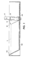
- Figure 1 is a sectional elevational view of a paper supply drawer, or tray, as would be found, for instance, in a printer, copier, or other office equipment, showing some essential features of the present invention.
- the drawer 100 defines a slanted surface 102, which is a generally flat surface disposed approximately 30 to 60 degrees from the vertical.
- a certain type of paper feeding apparatus exploits such a slanted surface, and it is desirable that a paper stack, such as indicated in Figure 1 as S, be disposed with one of its edges abutting such a slanted surface.
- one edge of a paper stack S is caused to abut slanted surface 102 by the presence and action of a plate 10 in contact with an opposite side of the stack.
- a stack S is initially placed in the drawer, with the typical vertical sides (such as when removed from a package), one side of the stack is in general contact with plate 10, which is in a substantially vertical "upright position" as shown.
- the plate 10 is moved to a substantially slanted position as shown in phantom and indicated as 10'.
- plate 10' is in the second position, the opposite side of stack S is pushed against slanted surface 102, and the stack S generally assumes a parallelogram shape, as shown.
- lever 12 which interacts with plate 10, and is shown in a position which is consistent with p late 10 being in its upright position. Shown in phantom and indicated as 12' is the lever in a position consistent with plate 10' being in its second position.
- the various possible mechanical means by which lever 12 interacts with plate 10 will be discussed below.
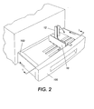
- FIG 2 is a perspective view of a portion of some office equipment, such as a printer or copier, in which a paper supply drawer or tray such as 100 is used.
- a paper supply drawer or tray such as 100
- lever 12 is shaped and located so that, when drawer 100 is pushed back into the machine, such as after loading a stack of paper therein, lever 12 contacts a "contact surface" of the machine and is thus pushed downward as the drawer 100 is closed.
- plate 10 is caused to move from its upright position to its slanted position, as described above.
- a stack of paper placed in the drawer 100 assumes the desired parallelogram shape and is pressed against the slanted surface 102.
- pushing the drawer 100 in causes the stack S to assume the parallelogram shape.
- the contact surface of a machine for this purpose can be an outer surface of the machine, as shown in Figure 2, or can be on a member internal to the machine.
- lever 12 can be in effect attached to a member within the body of the machine.
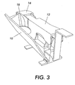
- FIG 3 is a perspective view of one embodiment of the present invention.
- plate 10 is movable between and upright position and a slanted position, as shown.
- Plate 10 assumes its slanted position when lever 12, which is pivotably mounted relative to a main portion 16 of a mechanism which supports p late 10 in a particular position, is in a down position ( as opposed to the up position, such as shown in Figure 2).
- the mechanism includes at least one camming surface, such as 18, which in effect transfers the motion of the downward positioning of lever 12 to move the plate 10 to its slanted position.
- the plate 10 returns to an upright position, either through the action of another camming surface, or of springs associated with the mechanism (not shown).
- Figure 4 is a perspective view of an alternate embodiment of the present invention.
- the plate 10 is once again caused to change position by the action of a lever 12, but the lever 12 slides relative to the basic mechanism instead of pivoting.
- the member forming lever 12 slides along a bar 20 while a surface thereof engages a camming surface 22 associated with plate 10.
- the plate 10 when lever 12 is slid to the right in the Figure, the plate 10 is moved to its slanted position; when the lever 12 is slid to the left, plate 10 returns to an upright position, aided by spring 24.
- a very simple mechanism is illustrated, many practical variations on the design can be contemplated to allow the sliding action of lever 12 and resulting positioning of plate 10.
- the lever 12 can be attached to or otherwise contact other surfaces (not shown) of the rest of a machine, to achieve the principle of "automatic" positioning of plate 10 to its slanted position when a paper tray or drawer is closed.
- the lever 12 can contact the outside of a machine, as largely shown in Figure 2 above, or contact or be attached to a member within the body of the machine.
- the lever 12 will contact a surface of the machine, be pushed to the right, and therefore place plate 10 in its slanted position.
- FIG. 5 is a perspective view of another possible embodiment of the present invention.
- the plate 10 is more or less directly moved, such as by a user's hand, into a slanted position as needed, and a lever 12, pivotably mounted on a surface (such as a main portion 16 as shown, or even a bottom surface of a paper tray or drawer), functions mainly as a "stop" to hold plate 10 in its slanted position.
- the "mechanism" for positioning plate 10 basically comprises the hinge on which plate 10 is mounted.
- a paper tray or drawer is typically provided with adjustable parts so that the tray can accommodate paper stock of various sizes.
- the position of plate 10 in terms of distance to slanted surface 102 be adjustable so that a stack S of a range of sizes can be placed properly in the tray.
- means for adjusting the position of plate 10 can include a track 14, which can be defined by a set of teeth or other structure in the body of tray 100. The plate 10 and its associated mechanism moves along track 14 as needed to conform to a stack S of a given size.
- FIG 6 is a perspective view of another aspect of the present invention, what can generally be called a slidable mount for adjusting a position of the plate 10, particularly relative to slanted surface 102 such as shown in Figure 1.
- a catch 30, which can be of any design, engages the teeth of track 14 to retain the plate 10 in a selected position relative to slanted surface 102.
- Any basic design of such a slidable mount can be provided, with or without the illustrated teeth in track 14.
- Another aspect of the invention is disposing the catch 30 or equivalent element underneath I ever 1 2 when I ever 12 is in a position consistent with plate 10 being in a slanted second position. T he position of lever 1 2 thus makes catch 30 largely inaccessible, so that the position of plate 10 cannot be changed when the plate is in its slanted position.
- plate 10 can be of any practical configuration, such as including openings, fingers, ridges, etc. as required to enhance performance.
- FIG. 7 is a simplified elevational view of an office machine, in this case a xerographic or electrostatographic printer 200 (which may also function as part of a copier or facsimile machine) embodying the present invention.
- Sheets from a tray 100 are stacked in a parallelogram-shaped stack S by the action of plate 10.
- Sheets are individually drawn by feed head 202 from stack S in a manner such as shown in the '969 patent, and sent through paper path 204.
- Each sheet receives marking material forming an image from charge receptor 206, and the marking material is fused in fuser 208 and deposited in tray 210 or other finishing device.
Landscapes
- Engineering & Computer Science (AREA)
- Mechanical Engineering (AREA)
- Sheets, Magazines, And Separation Thereof (AREA)
- Manual Feeding Of Sheets (AREA)
Abstract
Description
Claims (9)
- A printing apparatus, comprising:a paper tray for retaining a stack of sheets;a plate for engaging an edge of the stack of sheets; anda mechanism for selectably positioning the plate in an upright position and a slanted position.
- The apparatus of claim 1, the mechanism including a lever positionable in a first position and a second position, the first position being consistent with the plate being in the upright position and the second position consistent with the plate being in the slanted position.
- The apparatus of claim 1, wherein the lever is pivotably mounted relative to the mechanism.
- The apparatus of claim 1, wherein the I ever is slidably mounted relative to the mechanism.
- The apparatus of claim 1, the paper tray being slidable relative to a body of the apparatus; and the apparatus further comprising
means for positioning the lever in the second position when the paper tray is slid into the body of the apparatus. - The apparatus of claim 5, the apparatus defining a contact surface, and wherein the lever contacts the contact surface when the paper tray is slid into the body of the apparatus.
- The apparatus of claim 1, further comprising a slidable mount for the plate within the tray.
- The apparatus of claim 7, wherein the slidable mount is at least partially covered by the lever when the lever is in the second position.
- The apparatus of claim 1, further comprising a charge receptor for placing images on a sheet drawn from the stack.
Applications Claiming Priority (2)
| Application Number | Priority Date | Filing Date | Title |
|---|---|---|---|
| US22898 | 2001-12-20 | ||
| US10/022,898 US6644502B2 (en) | 2001-12-20 | 2001-12-20 | Sheet stack holding apparatus for a printer or copier |
Publications (3)
| Publication Number | Publication Date |
|---|---|
| EP1321400A2 true EP1321400A2 (en) | 2003-06-25 |
| EP1321400A3 EP1321400A3 (en) | 2004-05-06 |
| EP1321400B1 EP1321400B1 (en) | 2006-10-11 |
Family
ID=21812000
Family Applications (1)
| Application Number | Title | Priority Date | Filing Date |
|---|---|---|---|
| EP02028637A Expired - Lifetime EP1321400B1 (en) | 2001-12-20 | 2002-12-20 | Sheet stack holding apparatus for a printer or copier |
Country Status (7)
| Country | Link |
|---|---|
| US (1) | US6644502B2 (en) |
| EP (1) | EP1321400B1 (en) |
| JP (1) | JP3953948B2 (en) |
| BR (1) | BR0205160B1 (en) |
| CA (1) | CA2414324C (en) |
| DE (1) | DE60215292T2 (en) |
| MX (1) | MXPA02012741A (en) |
Families Citing this family (12)
| Publication number | Priority date | Publication date | Assignee | Title |
|---|---|---|---|---|
| JP3948428B2 (en) * | 2003-03-28 | 2007-07-25 | ブラザー工業株式会社 | Paper feed cassette and image forming apparatus provided with the same |
| US7152859B2 (en) * | 2004-06-15 | 2006-12-26 | Xerox Corporation | Sheet separator |
| JP4612872B2 (en) * | 2005-06-30 | 2011-01-12 | キヤノン株式会社 | Paper feeding device, recording device, and image reading device |
| JP2008105846A (en) * | 2006-10-27 | 2008-05-08 | Sony Corp | Recording medium protective sheet, transport tray, and image forming apparatus |
| US7543812B2 (en) * | 2006-10-31 | 2009-06-09 | Hewlett-Packard Development Company, L.P. | Media registration devices |
| JP2008110854A (en) * | 2006-10-31 | 2008-05-15 | Brother Ind Ltd | Image forming apparatus |
| KR101228930B1 (en) * | 2007-10-10 | 2013-02-01 | 삼성전자주식회사 | Medium feeding unit and image forming apparatus having the same |
| US7918444B2 (en) * | 2008-07-11 | 2011-04-05 | Lexmark International, Inc. | Media handling device having media shingling mechanism for providing uniform inter-page gap between successive media sheets |
| JP6668864B2 (en) * | 2016-03-22 | 2020-03-18 | コニカミノルタ株式会社 | Sheet material feeding device and image forming device |
| JP6939290B2 (en) * | 2017-09-07 | 2021-09-22 | 株式会社リコー | Sheet loading device, paper cassette, image forming device and composite image forming device |
| JP2020083573A (en) * | 2018-11-28 | 2020-06-04 | 京セラドキュメントソリューションズ株式会社 | Sheet positioning member, sheet storage device including the sheet positioning member, and image processing device including the sheet storage device |
| US11858765B2 (en) * | 2022-01-14 | 2024-01-02 | Toshiba Tec Kabushiki Kaisha | Sheet cassette |
Family Cites Families (13)
| Publication number | Priority date | Publication date | Assignee | Title |
|---|---|---|---|---|
| US4010944A (en) * | 1975-06-16 | 1977-03-08 | Koppers Company, Inc. | Blank feeding device having an adjustable and automatic positioning backstop means |
| JPS62175351A (en) * | 1986-01-29 | 1987-08-01 | Minolta Camera Co Ltd | Paper refeeder |
| JPH0684219B2 (en) * | 1986-07-10 | 1994-10-26 | レンゴ−株式会社 | Paper feeder |
| JPH04272034A (en) * | 1991-02-26 | 1992-09-28 | Hitachi Ltd | Paper sheet separation device |
| DE4131726A1 (en) | 1991-09-24 | 1993-03-25 | Bdt Buero Datentech Gmbh | METHOD AND DEVICE FOR SEPARATING SHEET-SHAPED RECORD CARRIERS |
| JPH06107351A (en) * | 1991-12-18 | 1994-04-19 | Seiko Epson Corp | Paper transport mechanism in paper feeder |
| US5286018A (en) * | 1992-09-29 | 1994-02-15 | Hewlett-Packard Company | Printer paper stack-handling apparatus |
| US5709381A (en) * | 1996-11-22 | 1998-01-20 | Hewlett-Packard Company | Printer media tray with automatic skewing of stack of media |
| US5803631A (en) * | 1997-06-12 | 1998-09-08 | Hewlett-Packard Company | Print media alignment apparatus and method |
| JP3721258B2 (en) * | 1998-05-01 | 2005-11-30 | 株式会社リコー | Paper feeder |
| JP2000034024A (en) * | 1998-07-16 | 2000-02-02 | Canon Inc | Sheet material feeding device and image forming device |
| JP3716679B2 (en) * | 1999-08-02 | 2005-11-16 | コニカミノルタビジネステクノロジーズ株式会社 | Sheet feeding device |
| JP2001278460A (en) * | 2000-03-30 | 2001-10-10 | Canon Inc | Sheet feeding apparatus and image forming apparatus having the same |
-
2001
- 2001-12-20 US US10/022,898 patent/US6644502B2/en not_active Expired - Fee Related
-
2002
- 2002-12-10 BR BRPI0205160-5A patent/BR0205160B1/en not_active IP Right Cessation
- 2002-12-13 CA CA002414324A patent/CA2414324C/en not_active Expired - Fee Related
- 2002-12-18 MX MXPA02012741A patent/MXPA02012741A/en active IP Right Grant
- 2002-12-18 JP JP2002366147A patent/JP3953948B2/en not_active Expired - Fee Related
- 2002-12-20 EP EP02028637A patent/EP1321400B1/en not_active Expired - Lifetime
- 2002-12-20 DE DE60215292T patent/DE60215292T2/en not_active Expired - Lifetime
Also Published As
| Publication number | Publication date |
|---|---|
| EP1321400A3 (en) | 2004-05-06 |
| US20030116907A1 (en) | 2003-06-26 |
| DE60215292D1 (en) | 2006-11-23 |
| BR0205160B1 (en) | 2011-08-09 |
| JP3953948B2 (en) | 2007-08-08 |
| CA2414324A1 (en) | 2003-06-20 |
| DE60215292T2 (en) | 2007-01-18 |
| BR0205160A (en) | 2004-06-29 |
| US6644502B2 (en) | 2003-11-11 |
| JP2003192147A (en) | 2003-07-09 |
| EP1321400B1 (en) | 2006-10-11 |
| CA2414324C (en) | 2006-06-27 |
| MXPA02012741A (en) | 2005-08-26 |
Similar Documents
| Publication | Publication Date | Title |
|---|---|---|
| US6916019B2 (en) | End fence, sheet feeding cassette, sheet feeding device, and image forming apparatus including the end fence | |
| US8194255B2 (en) | Image forming apparatus | |
| US6644502B2 (en) | Sheet stack holding apparatus for a printer or copier | |
| US8387971B2 (en) | Media-loaded device and image forming apparatus | |
| US8727342B2 (en) | Feeding device and image forming apparatus | |
| US7527258B2 (en) | Paper feed tray and image forming apparatus including the same | |
| CN100533287C (en) | Tandem color imaging device | |
| US7686292B2 (en) | Sheet feeding device and image forming apparatus | |
| US8279495B2 (en) | Image forming apparatus having cover lock device | |
| US7920819B2 (en) | Image forming apparatus with shiftable guide member for preventing curling of a transfer medium | |
| JP2003112847A (en) | Paper ejection tray device and image forming apparatus | |
| JPH08301461A (en) | Paper cassette device | |
| US8200117B2 (en) | Image forming apparatus having pivotable upper body | |
| JP2003040513A (en) | Paper ejection tray device and image forming apparatus | |
| JP4982872B2 (en) | Image forming apparatus | |
| JPH11222329A (en) | Sheet loading device and image forming device | |
| JP2018008759A (en) | Sheet supply apparatus and image forming apparatus | |
| EP2028569B1 (en) | Image forming apparatus | |
| JP4656048B2 (en) | Image forming apparatus | |
| JP3556558B2 (en) | Image forming device | |
| JP3586756B2 (en) | Paper width adjuster | |
| JP2001287840A (en) | Paper feeder and image forming apparatus | |
| US20200071106A1 (en) | Paper Feed Tray and Image Forming Apparatus | |
| JP2000219328A (en) | Sheet storage cassette and image forming apparatus provided with the cassette | |
| JP2004123282A (en) | Paper feed cassette |
Legal Events
| Date | Code | Title | Description |
|---|---|---|---|
| PUAI | Public reference made under article 153(3) epc to a published international application that has entered the european phase |
Free format text: ORIGINAL CODE: 0009012 |
|
| AK | Designated contracting states |
Designated state(s): AT BE BG CH CY CZ DE DK EE ES FI FR GB GR IE IT LI LU MC NL PT SE SI SK TR |
|
| AX | Request for extension of the european patent |
Extension state: AL LT LV MK RO |
|
| PUAL | Search report despatched |
Free format text: ORIGINAL CODE: 0009013 |
|
| AK | Designated contracting states |
Kind code of ref document: A3 Designated state(s): AT BE BG CH CY CZ DE DK EE ES FI FR GB GR IE IT LI LU MC NL PT SE SI SK TR |
|
| AX | Request for extension of the european patent |
Extension state: AL LT LV MK RO |
|
| 17P | Request for examination filed |
Effective date: 20041108 |
|
| AKX | Designation fees paid |
Designated state(s): DE FR GB |
|
| 17Q | First examination report despatched |
Effective date: 20050304 |
|
| GRAP | Despatch of communication of intention to grant a patent |
Free format text: ORIGINAL CODE: EPIDOSNIGR1 |
|
| GRAS | Grant fee paid |
Free format text: ORIGINAL CODE: EPIDOSNIGR3 |
|
| GRAA | (expected) grant |
Free format text: ORIGINAL CODE: 0009210 |
|
| AK | Designated contracting states |
Kind code of ref document: B1 Designated state(s): DE FR GB |
|
| REG | Reference to a national code |
Ref country code: GB Ref legal event code: FG4D |
|
| REF | Corresponds to: |
Ref document number: 60215292 Country of ref document: DE Date of ref document: 20061123 Kind code of ref document: P |
|
| ET | Fr: translation filed | ||
| PLBE | No opposition filed within time limit |
Free format text: ORIGINAL CODE: 0009261 |
|
| STAA | Information on the status of an ep patent application or granted ep patent |
Free format text: STATUS: NO OPPOSITION FILED WITHIN TIME LIMIT |
|
| 26N | No opposition filed |
Effective date: 20070712 |
|
| PGFP | Annual fee paid to national office [announced via postgrant information from national office to epo] |
Ref country code: DE Payment date: 20141121 Year of fee payment: 13 Ref country code: GB Payment date: 20141126 Year of fee payment: 13 |
|
| PGFP | Annual fee paid to national office [announced via postgrant information from national office to epo] |
Ref country code: FR Payment date: 20141217 Year of fee payment: 13 |
|
| REG | Reference to a national code |
Ref country code: DE Ref legal event code: R119 Ref document number: 60215292 Country of ref document: DE |
|
| GBPC | Gb: european patent ceased through non-payment of renewal fee |
Effective date: 20151220 |
|
| REG | Reference to a national code |
Ref country code: FR Ref legal event code: ST Effective date: 20160831 |
|
| PG25 | Lapsed in a contracting state [announced via postgrant information from national office to epo] |
Ref country code: GB Free format text: LAPSE BECAUSE OF NON-PAYMENT OF DUE FEES Effective date: 20151220 Ref country code: DE Free format text: LAPSE BECAUSE OF NON-PAYMENT OF DUE FEES Effective date: 20160701 |
|
| PG25 | Lapsed in a contracting state [announced via postgrant information from national office to epo] |
Ref country code: FR Free format text: LAPSE BECAUSE OF NON-PAYMENT OF DUE FEES Effective date: 20151231 |