EP1321207A1 - A method of die casting an iron alloy reinforced aluminium alloy engine block for an internal combustion engine and an engine block die cast according to the method - Google Patents
A method of die casting an iron alloy reinforced aluminium alloy engine block for an internal combustion engine and an engine block die cast according to the method Download PDFInfo
- Publication number
- EP1321207A1 EP1321207A1 EP01850217A EP01850217A EP1321207A1 EP 1321207 A1 EP1321207 A1 EP 1321207A1 EP 01850217 A EP01850217 A EP 01850217A EP 01850217 A EP01850217 A EP 01850217A EP 1321207 A1 EP1321207 A1 EP 1321207A1
- Authority
- EP
- European Patent Office
- Prior art keywords
- reinforcement
- bores
- engine block
- die cavity
- metal alloy
- Prior art date
- Legal status (The legal status is an assumption and is not a legal conclusion. Google has not performed a legal analysis and makes no representation as to the accuracy of the status listed.)
- Granted
Links
- 238000000034 method Methods 0.000 title claims abstract description 14
- 229910000838 Al alloy Inorganic materials 0.000 title claims abstract description 8
- 238000004512 die casting Methods 0.000 title claims abstract description 8
- 238000002485 combustion reaction Methods 0.000 title claims abstract description 6
- 229910000640 Fe alloy Inorganic materials 0.000 title claims abstract description 5
- 230000002787 reinforcement Effects 0.000 claims abstract description 61
- 229910001092 metal group alloy Inorganic materials 0.000 claims description 21
- 229910045601 alloy Inorganic materials 0.000 claims description 6
- 239000000956 alloy Substances 0.000 claims description 6
- 230000001427 coherent effect Effects 0.000 claims description 2
- 238000005266 casting Methods 0.000 abstract description 3
- CWYNVVGOOAEACU-UHFFFAOYSA-N Fe2+ Chemical compound [Fe+2] CWYNVVGOOAEACU-UHFFFAOYSA-N 0.000 description 4
- XEEYBQQBJWHFJM-UHFFFAOYSA-N Iron Chemical compound [Fe] XEEYBQQBJWHFJM-UHFFFAOYSA-N 0.000 description 3
- 229910052782 aluminium Inorganic materials 0.000 description 3
- XAGFODPZIPBFFR-UHFFFAOYSA-N aluminium Chemical compound [Al] XAGFODPZIPBFFR-UHFFFAOYSA-N 0.000 description 3
- 239000000463 material Substances 0.000 description 3
- 229910052751 metal Inorganic materials 0.000 description 3
- 239000002184 metal Substances 0.000 description 3
- 230000002093 peripheral effect Effects 0.000 description 2
- 229910001018 Cast iron Inorganic materials 0.000 description 1
- 230000005484 gravity Effects 0.000 description 1
- 229910052742 iron Inorganic materials 0.000 description 1
- 229910001234 light alloy Inorganic materials 0.000 description 1
- 239000007769 metal material Substances 0.000 description 1
- 238000007711 solidification Methods 0.000 description 1
- 230000008023 solidification Effects 0.000 description 1
Images

Classifications
-
- F—MECHANICAL ENGINEERING; LIGHTING; HEATING; WEAPONS; BLASTING
- F02—COMBUSTION ENGINES; HOT-GAS OR COMBUSTION-PRODUCT ENGINE PLANTS
- F02F—CYLINDERS, PISTONS OR CASINGS, FOR COMBUSTION ENGINES; ARRANGEMENTS OF SEALINGS IN COMBUSTION ENGINES
- F02F7/00—Casings, e.g. crankcases
- F02F7/0043—Arrangements of mechanical drive elements
- F02F7/0053—Crankshaft bearings fitted in the crankcase
-
- B—PERFORMING OPERATIONS; TRANSPORTING
- B22—CASTING; POWDER METALLURGY
- B22D—CASTING OF METALS; CASTING OF OTHER SUBSTANCES BY THE SAME PROCESSES OR DEVICES
- B22D17/00—Pressure die casting or injection die casting, i.e. casting in which the metal is forced into a mould under high pressure
- B22D17/20—Accessories: Details
- B22D17/22—Dies; Die plates; Die supports; Cooling equipment for dies; Accessories for loosening and ejecting castings from dies
- B22D17/24—Accessories for locating and holding cores or inserts
-
- B—PERFORMING OPERATIONS; TRANSPORTING
- B22—CASTING; POWDER METALLURGY
- B22D—CASTING OF METALS; CASTING OF OTHER SUBSTANCES BY THE SAME PROCESSES OR DEVICES
- B22D19/00—Casting in, on, or around objects which form part of the product
- B22D19/0009—Cylinders, pistons
-
- F—MECHANICAL ENGINEERING; LIGHTING; HEATING; WEAPONS; BLASTING
- F02—COMBUSTION ENGINES; HOT-GAS OR COMBUSTION-PRODUCT ENGINE PLANTS
- F02B—INTERNAL-COMBUSTION PISTON ENGINES; COMBUSTION ENGINES IN GENERAL
- F02B75/00—Other engines
- F02B75/16—Engines characterised by number of cylinders, e.g. single-cylinder engines
- F02B75/18—Multi-cylinder engines
- F02B2075/1804—Number of cylinders
- F02B2075/182—Number of cylinders five
-
- F—MECHANICAL ENGINEERING; LIGHTING; HEATING; WEAPONS; BLASTING
- F05—INDEXING SCHEMES RELATING TO ENGINES OR PUMPS IN VARIOUS SUBCLASSES OF CLASSES F01-F04
- F05C—INDEXING SCHEME RELATING TO MATERIALS, MATERIAL PROPERTIES OR MATERIAL CHARACTERISTICS FOR MACHINES, ENGINES OR PUMPS OTHER THAN NON-POSITIVE-DISPLACEMENT MACHINES OR ENGINES
- F05C2201/00—Metals
- F05C2201/02—Light metals
- F05C2201/021—Aluminium
-
- F—MECHANICAL ENGINEERING; LIGHTING; HEATING; WEAPONS; BLASTING
- F05—INDEXING SCHEMES RELATING TO ENGINES OR PUMPS IN VARIOUS SUBCLASSES OF CLASSES F01-F04
- F05C—INDEXING SCHEME RELATING TO MATERIALS, MATERIAL PROPERTIES OR MATERIAL CHARACTERISTICS FOR MACHINES, ENGINES OR PUMPS OTHER THAN NON-POSITIVE-DISPLACEMENT MACHINES OR ENGINES
- F05C2201/00—Metals
- F05C2201/04—Heavy metals
- F05C2201/0433—Iron group; Ferrous alloys, e.g. steel
- F05C2201/0436—Iron
- F05C2201/0439—Cast iron
Definitions
- the present invention relates to a method of high pressure die casting in a first metal, e. g. iron, alloy reinforcements for main bearing scantlings in a second metal, e. g. aluminum, alloy block for an internal combustion engine.
- a first metal e. g. iron
- alloy reinforcements for main bearing scantlings in a second metal e. g. aluminum
- alloy block for an internal combustion engine e.g. aluminum
- the present invention also relates to an engine block for an internal combustion engine made of said second metal alloy, comprising a plurality of cylinder bores, scantling means between adjoining cylinder bores, a bearing support on each scantling means, two surfaces on opposite sides of said bearing support for engagement with co-operating surfaces of an associated bearing cap, a bore for a bearing cap screw leading from each of said surfaces, an essentially semi-circular scantling reinforcement of said first metal alloy incorporated in each scantling means and bores in said scantling reinforcement forming a continuation of said bores in the scantling means.
- Engine blocks cast of a light alloy such as aluminum alloy have the primary advantage that they are light in comparison with cast iron alloy engine blocks, thereby offering the opportunity to achieve high power/ weight ratios in the engine. They, however, have the disadvantage that they are not as strong as iron alloy engine blocks and are not as well able to withstand the stresses encountered in engine operation. Particularly the scantlings in the engine, which provide support for the main bearings, are subject to high stresses.
- One purpose of the present invention is therefore to achieve a method described by way of introduction by means of which it is possible to securely fix the reinforcements in the die without the need to use other means than those normally used when die casting a light metal alloy engine block without scantling reinforcements.
- the cores for the main bearing screws are used to position the reinforcement and cylinder liner cores on the opposite side are used to clamp the reinforcement against the surface of the main bearing screw cores.
- Another purpose of the present invention is to achieve a ligth metal, preferably aluminum, alloy block described by way of introduction which is specially designed to be die cast using the method according to the present invention.
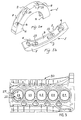
- Fig. 1a and Fig. 1b are perspective views from above and from below, respectively, of a scantling reinforcement to be die cast in an engine block according to one embodiment of the present invention
- Fig. 2 is a cross-section of the reinforcement shown i Fig. 1a and Fig. 1b and cylinder liners in a die casting die
- Fig. 3 is a top view of a light metal alloy, e. g. aluminum alloy, block according to one embodiment of the present invention.
- a light metal alloy e. g. aluminum alloy
- Fig. 1a and 1b 1 generally designates a scantling reinforcement made of a ferrous metal alloy.
- the reinforcement 1 is essentially semi-circular with inner and outer semi-circular surfaces 2 and 3, respectively, and opposite flat surfaces 4 and 5.
- the end portions of the reinforcement 1 have bores 6 for main bearing bolts (not shown), by means of which a main bearing cap can be attached to the engine block at the scantling location.
- the central portion of the outer surface 3 has a flat area 7, the purpose of which will be described below with reference to Fig. 2.
- the outer surface 3 is formed with a peripheral depression or channel 8 on each side of the central flat area 7.
- the inner surface 4 is formed with a peripheral depression or channel 9 which runs from one of the bores 6 to the other.
- the outer channel 8 communicates with the inner channels 9 via through-channels 10.
- the material in said channels 8, 9 and 10 forms a coherent mass with the material in the engine block to secure a mechanical grip between the ferrous reinforcement 1 and the surrounding light metal material.
- Fig. 2 designates a lower portion of a die casting die.
- Reinforcements 1 are first inserted in cavities 21 in the die portion 20 and positioned by cores (not shown) for the bores 6 for main bearing screws.
- Fig. 2 also shows three consecutive cylinder liners 22 with cylinder bores 23. After positioning of the reinforcements 1 a liner core 25 is inserted into each liner 22, so that bottom surfaces 26 rest on edges 27 of the above mentioned flat areas 7 of the surfaces 3, thereby securing the reinforcements 1 in the die cavity 21 before a molten light metal alloy such as an aluminum alloy is introduced and pressurized in the die cavity 21.
- a molten light metal alloy such as an aluminum alloy
- Fig. 3 shows a light metal alloy block 30 for a five cylinder engine with six reinforcements made of a ferrous metal alloy 1 cast in according to the above described method.
- Fig. 3 the edges 27 of the flat areas 7 of the surfaces 3 of the reinforcement 1 in each scantling 28 can be seen.
- cylinder liner cores are used to secure the reinforcements from above. It is also possible within the scope of the invention to design the reinforcements with portions projecting upwards and positioned such that cores for other cavities in the engine block than the cylinder bores could be used for the same purpose.
Landscapes
- Engineering & Computer Science (AREA)
- Mechanical Engineering (AREA)
- Chemical & Material Sciences (AREA)
- Combustion & Propulsion (AREA)
- General Engineering & Computer Science (AREA)
- Cylinder Crankcases Of Internal Combustion Engines (AREA)
- Molds, Cores, And Manufacturing Methods Thereof (AREA)
Abstract
Description
- The present invention relates to a method of high pressure die casting in a first metal, e. g. iron, alloy reinforcements for main bearing scantlings in a second metal, e. g. aluminum, alloy block for an internal combustion engine.
- The present invention also relates to an engine block for an internal combustion engine made of said second metal alloy, comprising a plurality of cylinder bores, scantling means between adjoining cylinder bores, a bearing support on each scantling means, two surfaces on opposite sides of said bearing support for engagement with co-operating surfaces of an associated bearing cap, a bore for a bearing cap screw leading from each of said surfaces, an essentially semi-circular scantling reinforcement of said first metal alloy incorporated in each scantling means and bores in said scantling reinforcement forming a continuation of said bores in the scantling means.
- Engine blocks cast of a light alloy such as aluminum alloy have the primary advantage that they are light in comparison with cast iron alloy engine blocks, thereby offering the opportunity to achieve high power/ weight ratios in the engine. They, however, have the disadvantage that they are not as strong as iron alloy engine blocks and are not as well able to withstand the stresses encountered in engine operation. Particularly the scantlings in the engine, which provide support for the main bearings, are subject to high stresses.
- It is previously known to increase the strength of the scantlings in an aluminum alloy engine block by casting an iron core reinforcement in the aluminum material of each scantling. Such a reinforcement forms a semi-circular surface facing the main bearing. According to a previously known method (US pat. no. 4,643,145) the reinforcements for the scantlings are positioned in the engine block die by means of rods which are screwed into the bores for the main bearing screws. The die is then gravity filled with molten aluminum alloy to cast the block around the reinforcements. After solidification the casting is removed from the die and the rods removed from the reinforcements.
- To be able to high pressure die casting in reinforcements made of a ferrous metal alloy in an engine block made of a light metal alloy it is essential that the reinforcements are securly fixed in the die, so the they will not become dislocated in the die when the molten light metal alloy is introduced. One purpose of the present invention is therefore to achieve a method described by way of introduction by means of which it is possible to securely fix the reinforcements in the die without the need to use other means than those normally used when die casting a light metal alloy engine block without scantling reinforcements.
- This can be achieved according to the invention by means of a method, which comprises the steps of placing a first metal alloy reinforcement having bores for main bearing screws and a semi-circular surface facing the main bearing between said bores at each scantling location in the die cavity, so that first core means in the die cavity protrude into said bores on one side of the reinforcement, fixing the reinforcement in the die cavity by placing second core means in the die cavity against a surface on the opposite side of the reinforcement, and introducing and pressurizing a molten second metal alloy in the die cavity.
- By clamping the reinforcement between existing cores on opposite sides of the reinforcement there is no need for other means such as fixing rods or the like. Preferably, according to the invention, the cores for the main bearing screws are used to position the reinforcement and cylinder liner cores on the opposite side are used to clamp the reinforcement against the surface of the main bearing screw cores.
- Another purpose of the present invention is to achieve a ligth metal, preferably aluminum, alloy block described by way of introduction which is specially designed to be die cast using the method according to the present invention.
- This can be achieved according to the invention by virtue of the fact that the maximum width of said reinforcement, in the axial direction of the engine block, is larger than than the minimum thickness of the cylinder walls between adjoining cylinder bores.
- This means that an area of the surface of the reinforcement facing the top of the engine block will be exposed inside the cylinder bore and, when the cylinder liner core is inserted into the liner, the bottom surface of the liner core will eventually hit this exposed reinforcement surface and press the reinforcement against the main bearing screw cores on the opposite side of the reinforcement.
- The invention will be described in more detail below with reference to the accompanying drawings, wherein Fig. 1a and Fig. 1b are perspective views from above and from below, respectively, of a scantling reinforcement to be die cast in an engine block according to one embodiment of the present invention, Fig. 2 is a cross-section of the reinforcement shown i Fig. 1a and Fig. 1b and cylinder liners in a die casting die and Fig. 3 is a top view of a light metal alloy, e. g. aluminum alloy, block according to one embodiment of the present invention.
- In Fig. 1a and 1b, 1 generally designates a scantling reinforcement made of a ferrous metal alloy. The reinforcement 1 is essentially semi-circular with inner and outer
semi-circular surfaces 2 and 3, respectively, and opposite flat surfaces 4 and 5. The end portions of the reinforcement 1 havebores 6 for main bearing bolts (not shown), by means of which a main bearing cap can be attached to the engine block at the scantling location. The central portion of the outer surface 3 has a flat area 7, the purpose of which will be described below with reference to Fig. 2. Also, the outer surface 3 is formed with a peripheral depression or channel 8 on each side of the central flat area 7. The inner surface 4 is formed with a peripheral depression or channel 9 which runs from one of thebores 6 to the other. The outer channel 8 communicates with the inner channels 9 via through-channels 10. In the finished engine block the material insaid channels 8, 9 and 10 forms a coherent mass with the material in the engine block to secure a mechanical grip between the ferrous reinforcement 1 and the surrounding light metal material. - In Fig. 2, 20 designates a lower portion of a die casting die. Reinforcements 1 are first inserted in
cavities 21 in thedie portion 20 and positioned by cores (not shown) for thebores 6 for main bearing screws. Fig. 2 also shows threeconsecutive cylinder liners 22 withcylinder bores 23. After positioning of the reinforcements 1 aliner core 25 is inserted into eachliner 22, so thatbottom surfaces 26 rest onedges 27 of the above mentioned flat areas 7 of the surfaces 3, thereby securing the reinforcements 1 in thedie cavity 21 before a molten light metal alloy such as an aluminum alloy is introduced and pressurized in thedie cavity 21. - Fig. 3 shows a light
metal alloy block 30 for a five cylinder engine with six reinforcements made of a ferrous metal alloy 1 cast in according to the above described method. In Fig. 3 theedges 27 of the flat areas 7 of the surfaces 3 of the reinforcement 1 in each scantling 28 can be seen. - According to the above described preferred method, cylinder liner cores are used to secure the reinforcements from above. It is also possible within the scope of the invention to design the reinforcements with portions projecting upwards and positioned such that cores for other cavities in the engine block than the cylinder bores could be used for the same purpose.
Claims (9)
- A method of high pressure die casting in first metal alloy reinforcements for main bearings scantlings in a second metal alloy engine block for an internal combustion engine, characterized by the following steps:placing a first metal alloy reinforcement (1) having bores (6) for main bearing screws and an essentially semi-circular surface (2) facing the main bearings between said bores at each scantling location (28) in a die cavity (21), so that first core means in the die cavity protrude into said bores on one side of the reinforcement;fixing the reinforcement in the die cavity by placing second core means (25) in the die cavity against a surface (27) on the opposite side of the reinforcement;and introducing and pressurizing a molten second metal alloy in the die cavity.
- A method according to claim 1, characterized in that the reinforcement (1) is placed in the die cavity (21), so that cores for main bearing screws protrude into the bores (6) on said one side of the reinforcement.
- A method according to claim 1 or 2, characterized in that the reinforcement (1) is fixed in the die cavity (21) by placing a cylinder liner core (25) against the surface (27) on said opposite side of the reinforcement.
- A method according to one of claims 1-3, characterized in that reinforcements (1) made of an iron alloy is placed in the die cavity (21) and that a molten alumnium alloy is thereafter introduced and pressurized in the die cavity.
- A metal alloy block for an internal combustion engine, comprising a plurality of cylinder bores, scantling means (28) for main bearing between adjoining cylinder bores, a scantling reinforement (1) made of a metal alloy different from the metal alloy of the block and having an essentially semi-circular surface (2) facing said main bearing incorporated in each scantling means and bores for main bearing screws in said reinforcement, characterized in that the maximum width of said reinforcement (1) in the axial direction of the engine block (30) is larger than the minimum thickness of the cylinder walls between adjoining cylinder bores (23).
- Engine block according to claim 5, characterized in that an outer peripherial surface (3) of said reinforcement (1) has a flat central area (7).
- Engine block according to claim 5 or 6, characterized in that said depressions (8, 9) are formed in opposite peripherial surfaces (2, 3) of the reinforcement (1).
- Engine block according to claim 7, characterized in that said reinforcement (1) has at least one through-channel (10) in a portion between said bores (6), said through -channel and depressions (8, 9) being filled with the same alloy as and forming a coherent mass with the surrounding metal alloy of the block
- Engine block according to one of claims 5-8, characterized in that the engine block is made of an aluminum alloy and the reinforcement of an iron alloy.
Priority Applications (3)
| Application Number | Priority Date | Filing Date | Title |
|---|---|---|---|
| EP01850217A EP1321207B1 (en) | 2001-12-21 | 2001-12-21 | A method of die casting an iron alloy reinforced aluminium alloy engine block for an internal combustion engine and an engine block die cast according to the method |
| DE60117751T DE60117751T2 (en) | 2001-12-21 | 2001-12-21 | A method of die casting an engine block from an iron alloy reinforced aluminum alloy and engine block cast according to this method |
| US10/248,142 US7047928B2 (en) | 2001-12-21 | 2002-12-20 | Method for casting an iron alloy reinforced aluminum alloy engine block |
Applications Claiming Priority (1)
| Application Number | Priority Date | Filing Date | Title |
|---|---|---|---|
| EP01850217A EP1321207B1 (en) | 2001-12-21 | 2001-12-21 | A method of die casting an iron alloy reinforced aluminium alloy engine block for an internal combustion engine and an engine block die cast according to the method |
Publications (2)
| Publication Number | Publication Date |
|---|---|
| EP1321207A1 true EP1321207A1 (en) | 2003-06-25 |
| EP1321207B1 EP1321207B1 (en) | 2006-03-08 |
Family
ID=8184902
Family Applications (1)
| Application Number | Title | Priority Date | Filing Date |
|---|---|---|---|
| EP01850217A Expired - Lifetime EP1321207B1 (en) | 2001-12-21 | 2001-12-21 | A method of die casting an iron alloy reinforced aluminium alloy engine block for an internal combustion engine and an engine block die cast according to the method |
Country Status (3)
| Country | Link |
|---|---|
| US (1) | US7047928B2 (en) |
| EP (1) | EP1321207B1 (en) |
| DE (1) | DE60117751T2 (en) |
Cited By (1)
| Publication number | Priority date | Publication date | Assignee | Title |
|---|---|---|---|---|
| EP1769865A3 (en) * | 2005-09-30 | 2009-07-08 | Fuji Jukogyo Kabushiki Kaisha | Iron species preform |
Families Citing this family (5)
| Publication number | Priority date | Publication date | Assignee | Title |
|---|---|---|---|---|
| JP2004028253A (en) * | 2002-06-27 | 2004-01-29 | Suzuki Motor Corp | Crankshaft support device |
| JP2007514550A (en) * | 2003-12-18 | 2007-06-07 | テネドーラ ネマク エス.エー.デ シー.ヴイ. | Method and apparatus for producing durable thin-walled castings |
| US20050247428A1 (en) * | 2004-04-20 | 2005-11-10 | Tenedora Nemak, S.A. De C.V. | Method and apparatus for casting aluminum engine blocks with cooling liquid passage in ultra thin interliner webs |
| DE102015201994A1 (en) * | 2015-02-05 | 2016-08-11 | Ford Global Technologies, Llc | Reciprocating engine, motor vehicle |
| US10125720B2 (en) | 2016-07-12 | 2018-11-13 | Ford Motor Company | Casting assembly and method to provide magnetic retention for over-molded inserts in die cast tooling |
Citations (4)
| Publication number | Priority date | Publication date | Assignee | Title |
|---|---|---|---|---|
| EP0052818A1 (en) * | 1980-11-26 | 1982-06-02 | Nissan Motor Co., Ltd. | Cylinder block of internal combustion engine |
| EP0145393A2 (en) * | 1983-12-10 | 1985-06-19 | Ae Plc | The reinforcement of engine blocks |
| EP0554575A1 (en) * | 1992-01-06 | 1993-08-11 | Honda Giken Kogyo Kabushiki Kaisha | Cylinder block |
| DE10026216A1 (en) * | 1999-08-19 | 2001-03-01 | Avl List Gmbh | Cylinder crankcase for IC engines has outer structure of pref. aluminum/ magnesium alloy, and cast-in component with bearing bracket, of cast steel |
Family Cites Families (9)
| Publication number | Priority date | Publication date | Assignee | Title |
|---|---|---|---|---|
| US256038A (en) * | 1882-04-04 | Ingot-mold shield | ||
| US1288326A (en) * | 1917-05-02 | 1918-12-17 | John F West | Mold-jacket and method of making the same. |
| DE3525747A1 (en) * | 1985-07-19 | 1987-01-29 | Pfeiffer Vakuumtechnik | SYSTEM AND METHOD FOR TREATING METALS IN VACUUM |
| US5203854A (en) * | 1991-02-06 | 1993-04-20 | Ab Volvo | Main bearing cap for internal combustion engines |
| US5390723A (en) * | 1992-03-09 | 1995-02-21 | Mohla; Prem P. | Method of treating casting metals |
| SE9500260L (en) * | 1994-02-11 | 1995-08-12 | Fischer Georg Giessereianlagen | Process and apparatus for cleaning of cast trees |
| JP3262461B2 (en) * | 1994-09-09 | 2002-03-04 | タイホー工業株式会社 | Casting heat treatment equipment |
| USH1769H (en) * | 1995-06-06 | 1999-01-05 | The United States Of America As Represented By The Secretary Of The Air Force | Optimized recursive foundry tooling fabrication method |
| JP3766269B2 (en) * | 2000-11-29 | 2006-04-12 | 東芝機械株式会社 | Ingot supply device and ingot supply method |
-
2001
- 2001-12-21 EP EP01850217A patent/EP1321207B1/en not_active Expired - Lifetime
- 2001-12-21 DE DE60117751T patent/DE60117751T2/en not_active Expired - Lifetime
-
2002
- 2002-12-20 US US10/248,142 patent/US7047928B2/en not_active Expired - Lifetime
Patent Citations (4)
| Publication number | Priority date | Publication date | Assignee | Title |
|---|---|---|---|---|
| EP0052818A1 (en) * | 1980-11-26 | 1982-06-02 | Nissan Motor Co., Ltd. | Cylinder block of internal combustion engine |
| EP0145393A2 (en) * | 1983-12-10 | 1985-06-19 | Ae Plc | The reinforcement of engine blocks |
| EP0554575A1 (en) * | 1992-01-06 | 1993-08-11 | Honda Giken Kogyo Kabushiki Kaisha | Cylinder block |
| DE10026216A1 (en) * | 1999-08-19 | 2001-03-01 | Avl List Gmbh | Cylinder crankcase for IC engines has outer structure of pref. aluminum/ magnesium alloy, and cast-in component with bearing bracket, of cast steel |
Cited By (2)
| Publication number | Priority date | Publication date | Assignee | Title |
|---|---|---|---|---|
| EP1769865A3 (en) * | 2005-09-30 | 2009-07-08 | Fuji Jukogyo Kabushiki Kaisha | Iron species preform |
| US7629057B2 (en) | 2005-09-30 | 2009-12-08 | Fuji Jukogyo Kabushiki Kaisha | Iron species preform |
Also Published As
| Publication number | Publication date |
|---|---|
| DE60117751T2 (en) | 2006-08-17 |
| US20030116114A1 (en) | 2003-06-26 |
| US7047928B2 (en) | 2006-05-23 |
| DE60117751D1 (en) | 2006-05-04 |
| EP1321207B1 (en) | 2006-03-08 |
Similar Documents
| Publication | Publication Date | Title |
|---|---|---|
| CN101547760B (en) | Casting mould for casting a cast part and use of such a casting mould | |
| US4599772A (en) | Method for reinforcement of pistons of aluminum or aluminum alloy | |
| EP0145393B1 (en) | The reinforcement of engine blocks | |
| US20150020757A1 (en) | Engine with cylinder liner with bonding layer | |
| US10690087B2 (en) | Aluminum cylinder block and method of manufacture | |
| US6845807B1 (en) | Metal casting core assembly for casting a crankshaft | |
| EP1321207B1 (en) | A method of die casting an iron alloy reinforced aluminium alloy engine block for an internal combustion engine and an engine block die cast according to the method | |
| US4903652A (en) | Cylinder liner insert and method of making engine block therewith | |
| EP0149313B1 (en) | Internal combustion engine | |
| CA2381015A1 (en) | Casting of engine blocks | |
| EP0476506B1 (en) | Method of manufacturing cylinder block of engine | |
| US20050173091A1 (en) | Method and apparatus for manufacturing strong thin-walled castings | |
| US7270168B2 (en) | Method for moulding light alloy cast parts, in particular cylinder blocks | |
| AU2003277864A1 (en) | Mold core arrangement for producing a cylinder crankcase with a separate water cooling area | |
| US5581881A (en) | Method of making a cylinder barrel having ceramic bore liners | |
| US20050150476A1 (en) | Combination of cylinder liners consisting of a light metal alloy | |
| US7293598B2 (en) | Cylinder liner improvements | |
| US6415848B1 (en) | Metal mold arrangement for producing cylinder block | |
| EP1769865B1 (en) | Iron species preform | |
| US11554413B2 (en) | Hybrid cam bore sand core with metal chills for cast aluminum block | |
| JPS62161453A (en) | Production of closed deck type cylinder block with wet liner | |
| JP2002089362A (en) | Structure of cylinder block | |
| JPH10176597A (en) | Method of manufacturing piston for internal combustion engine | |
| JPH0229427B2 (en) | ||
| JPH09242598A (en) | Cylinder block insert member and method for manufacturing cylinder block |
Legal Events
| Date | Code | Title | Description |
|---|---|---|---|
| PUAI | Public reference made under article 153(3) epc to a published international application that has entered the european phase |
Free format text: ORIGINAL CODE: 0009012 |
|
| AK | Designated contracting states |
Designated state(s): AT BE CH CY DE DK ES FI FR GB GR IE IT LI LU MC NL PT SE TR |
|
| AX | Request for extension of the european patent |
Extension state: AL LT LV MK RO SI |
|
| 17P | Request for examination filed |
Effective date: 20031205 |
|
| AKX | Designation fees paid |
Designated state(s): DE GB SE |
|
| GRAP | Despatch of communication of intention to grant a patent |
Free format text: ORIGINAL CODE: EPIDOSNIGR1 |
|
| GRAS | Grant fee paid |
Free format text: ORIGINAL CODE: EPIDOSNIGR3 |
|
| GRAA | (expected) grant |
Free format text: ORIGINAL CODE: 0009210 |
|
| RAP1 | Party data changed (applicant data changed or rights of an application transferred) |
Owner name: FORD GLOBAL TECHNOLOGIES, LLC |
|
| AK | Designated contracting states |
Kind code of ref document: B1 Designated state(s): DE GB SE |
|
| REG | Reference to a national code |
Ref country code: GB Ref legal event code: FG4D |
|
| REF | Corresponds to: |
Ref document number: 60117751 Country of ref document: DE Date of ref document: 20060504 Kind code of ref document: P |
|
| RAP2 | Party data changed (patent owner data changed or rights of a patent transferred) |
Owner name: FORD GLOBAL TECHNOLOGIES, LLC. |
|
| REG | Reference to a national code |
Ref country code: SE Ref legal event code: TRGR |
|
| PLBE | No opposition filed within time limit |
Free format text: ORIGINAL CODE: 0009261 |
|
| STAA | Information on the status of an ep patent application or granted ep patent |
Free format text: STATUS: NO OPPOSITION FILED WITHIN TIME LIMIT |
|
| 26N | No opposition filed |
Effective date: 20061211 |
|
| REG | Reference to a national code |
Ref country code: GB Ref legal event code: 732E Free format text: REGISTERED BETWEEN 20111020 AND 20111025 |
|
| REG | Reference to a national code |
Ref country code: DE Ref legal event code: R082 Ref document number: 60117751 Country of ref document: DE Representative=s name: HOFFMANN - EITLE, DE |
|
| REG | Reference to a national code |
Ref country code: DE Ref legal event code: R081 Ref document number: 60117751 Country of ref document: DE Owner name: VOLVO CAR CORPORATION, SE Free format text: FORMER OWNER: FORD GLOBAL TECHNOLOGIES, LLC, DEARBORN, MICH., US Effective date: 20120207 Ref country code: DE Ref legal event code: R082 Ref document number: 60117751 Country of ref document: DE Representative=s name: HOFFMANN - EITLE PATENT- UND RECHTSANWAELTE PA, DE Effective date: 20120207 Ref country code: DE Ref legal event code: R082 Ref document number: 60117751 Country of ref document: DE Representative=s name: HOFFMANN - EITLE, DE Effective date: 20120207 Ref country code: DE Ref legal event code: R081 Ref document number: 60117751 Country of ref document: DE Owner name: VOLVO CAR CORPORATION, SE Free format text: FORMER OWNER: FORD GLOBAL TECHNOLOGIES, LLC, DEARBORN, US Effective date: 20120207 |
|
| PGFP | Annual fee paid to national office [announced via postgrant information from national office to epo] |
Ref country code: SE Payment date: 20141215 Year of fee payment: 14 Ref country code: GB Payment date: 20141209 Year of fee payment: 14 |
|
| PGFP | Annual fee paid to national office [announced via postgrant information from national office to epo] |
Ref country code: DE Payment date: 20151210 Year of fee payment: 15 |
|
| REG | Reference to a national code |
Ref country code: SE Ref legal event code: EUG |
|
| GBPC | Gb: european patent ceased through non-payment of renewal fee |
Effective date: 20151221 |
|
| PG25 | Lapsed in a contracting state [announced via postgrant information from national office to epo] |
Ref country code: SE Free format text: LAPSE BECAUSE OF NON-PAYMENT OF DUE FEES Effective date: 20151222 |
|
| PG25 | Lapsed in a contracting state [announced via postgrant information from national office to epo] |
Ref country code: GB Free format text: LAPSE BECAUSE OF NON-PAYMENT OF DUE FEES Effective date: 20151221 |
|
| REG | Reference to a national code |
Ref country code: DE Ref legal event code: R119 Ref document number: 60117751 Country of ref document: DE |
|
| PG25 | Lapsed in a contracting state [announced via postgrant information from national office to epo] |
Ref country code: DE Free format text: LAPSE BECAUSE OF NON-PAYMENT OF DUE FEES Effective date: 20170701 |