EP1321061A2 - Slide fastener with separable bottom stop assembly and method of manufacturing the same - Google Patents
Slide fastener with separable bottom stop assembly and method of manufacturing the same Download PDFInfo
- Publication number
- EP1321061A2 EP1321061A2 EP02258444A EP02258444A EP1321061A2 EP 1321061 A2 EP1321061 A2 EP 1321061A2 EP 02258444 A EP02258444 A EP 02258444A EP 02258444 A EP02258444 A EP 02258444A EP 1321061 A2 EP1321061 A2 EP 1321061A2
- Authority
- EP
- European Patent Office
- Prior art keywords
- fastener
- core portion
- core
- pin
- tape
- Prior art date
- Legal status (The legal status is an assumption and is not a legal conclusion. Google has not performed a legal analysis and makes no representation as to the accuracy of the status listed.)
- Granted
Links
Images



Classifications
-
- A—HUMAN NECESSITIES
- A44—HABERDASHERY; JEWELLERY
- A44B—BUTTONS, PINS, BUCKLES, SLIDE FASTENERS, OR THE LIKE
- A44B19/00—Slide fasteners
- A44B19/24—Details
- A44B19/38—Means at the end of stringer by which the slider can be freed from one stringer, e.g. stringers can be completely separated from each other
- A44B19/384—Separable slide fasteners with quick opening devices
- A44B19/388—Bottom end stop means for quick opening slide fasteners
-
- A—HUMAN NECESSITIES
- A44—HABERDASHERY; JEWELLERY
- A44B—BUTTONS, PINS, BUCKLES, SLIDE FASTENERS, OR THE LIKE
- A44B19/00—Slide fasteners
- A44B19/24—Details
- A44B19/36—Means for permanently uniting the stringers at the end; Means for stopping movement of slider at the end
-
- Y—GENERAL TAGGING OF NEW TECHNOLOGICAL DEVELOPMENTS; GENERAL TAGGING OF CROSS-SECTIONAL TECHNOLOGIES SPANNING OVER SEVERAL SECTIONS OF THE IPC; TECHNICAL SUBJECTS COVERED BY FORMER USPC CROSS-REFERENCE ART COLLECTIONS [XRACs] AND DIGESTS
- Y10—TECHNICAL SUBJECTS COVERED BY FORMER USPC
- Y10T—TECHNICAL SUBJECTS COVERED BY FORMER US CLASSIFICATION
- Y10T24/00—Buckles, buttons, clasps, etc.
- Y10T24/25—Zipper or required component thereof
- Y10T24/2511—Zipper or required component thereof with distinct, stationary means for anchoring slider
- Y10T24/2513—Zipper or required component thereof with distinct, stationary means for anchoring slider and for aligning surfaces or obstructing slider movement
-
- Y—GENERAL TAGGING OF NEW TECHNOLOGICAL DEVELOPMENTS; GENERAL TAGGING OF CROSS-SECTIONAL TECHNOLOGIES SPANNING OVER SEVERAL SECTIONS OF THE IPC; TECHNICAL SUBJECTS COVERED BY FORMER USPC CROSS-REFERENCE ART COLLECTIONS [XRACs] AND DIGESTS
- Y10—TECHNICAL SUBJECTS COVERED BY FORMER USPC
- Y10T—TECHNICAL SUBJECTS COVERED BY FORMER US CLASSIFICATION
- Y10T24/00—Buckles, buttons, clasps, etc.
- Y10T24/25—Zipper or required component thereof
- Y10T24/2593—Zipper or required component thereof including complementary, aligning means attached to ends of interlocking surfaces
Definitions
- the present invention relates to a slide fastener having a separable bottom stop assembly at a bottom stopper portion thereof and a method of manufacturing the same.
- this method requires a heating apparatus for applying enough heat to the core portion and its periphery in preliminary heat-setting so as to stabilize the folded configuration of the fastener tape.
- its thermal history is so large that the core portion and the surrounding portion thereof become brittle. Consequently, the insert pin and the box pin attached around the core portion easily split at their boundary.
- the configurations of the core portion and its periphery in a cavity may not be maintained upon molding of the separable bottom stop assembly.
- An object of this invention is to provide a slide fastener and a method for efficiently manufacturing the same, in which an insert pin or a box pin with substantially even thickness is formed around a core portion without other equipment than an injection-molding machine and without making the core portion and its periphery brittle.
- a slide fastener having linear fastener element rows along opposing side edges of a pair of fastener tapes and the separable bottom stop assembly comprising an insert pin, a box pin and a box made of synthetic resin at an end thereof, said insert pin and said box pin being formed integrally by injection molding so as to include core portions adjacent end portions of the fastener element rows.
- the insert pin and the box pin have peripheral shapes allowing themselves to be inserted into element row guide grooves of a slider.
- the insert pin and the box pin are molded integrally such that the entire insert pin and box pin incline toward a rear face side of the tape from their inner side edges to outer side edges relative to a tape plane of the fastener, said rear face side having no core thread of the'core portion.
- the sectional shapes of the insert pin and the box pin of the present invention is not different from the conventional ones.
- the insert pin and the box pin are inclined at a predetermined angle from their inner edges to their outer edges toward the rear face side, or the side without core thread, opposite to the front face to which the fastener element row is attached. Consequently, a sufficient amount of resin material for the insert pin and the box pin is supplied also to the rear face side of the core portion.
- the thickness of the resin on the rear face side can be approximated to the thickness of the resin on the front face side. Accordingly, possibility of damage due to peel of resin at the rear face side of the core portion can be minimized.
- the slide fastener having above-described structure can be produced by the following two manufacturing methods.
- the fastener is provided with the linear fastener element rows along the opposing side edges of a pair of the fastener tapes and the separable bottom stop assembly comprising the insert pin, the box pin and the box made of synthetic resin, said insert pin and said box pin being molded integrally so as to include the core portion at the bottom end of each of the fastener element rows.
- This manufacturing method comprises: introducing the core portion into an injection-molding die for the insert pin or the box pin; pressing the core portion disposed in the molding cavity from the rear face side without the core thread to the front face side of the fastener tape; and injecting molten resin into the molding cavity so that the molten resin flows into molding spaces on the front and rear face sides of the core portion and fixes to the periphery of the core portion.
- the fastener is provided with the linear fastener element rows along the opposing side edges of a pair of the fastener tapes and the separable bottom stop assembly comprising the insert pin, the box pin and the box made of synthetic resin, said insert pin and said box pin being molded integrally so as to include the core portion at the bottom end of each of the fastener element rows .
- This manufacturing method further comprises: forming the molding cavity for the insert pin or the box pin in the injection-molding die so that said cavity may incline relative to a core-portion-insertion plane toward a rear face side without the core thread of the fastener tape; introducing the core portion into the molding die for the insert pin or the box pin; maintaining the core portion without bending a tape portion around its border with the core portion disposed in the molding cavity; and injecting molten resin into the molding cavity so that the molten resin flows into molding spaces on the front and rear face sides of the core portion and fixes to the periphery of the core portion.
- an inner face on the front face side of the molded product and an inner face on the rear face side thereof are substantially parallel to the fastener tape in the section of the molding cavity, as in conventional ones.
- a pin for pressing the core portion from the rear face side to the front face side of the fastener tape is provided protrusively in the cavity. If so, the core portion inclines downward due to its own weight so as not to block flow of molten resin into the rear face side of the core portion.
- the molding cavity is formed such that its entire section inclines relative to the core-portion-insertion plane toward the rear face side of the fastener tape.
- the pin for maintaining the core portion in parallel to the tape plane of the fastener tape is provided protrusively in the cavity. If so, the core portion never inclines downward due to its own weight and spaces into which a sufficient amount of molten resin flows can be secured on both the front and rear face sides of the core portion. Consequently, the molten resin smoothly flows into the rear face side of the core portion.
- a conventional injection-molding machine for producing the separable bottom stop assembly can be used directly if the molding cavity in the molding die is formed as described above, while the manufacturing method disclosed in the above patent publication requires such special equipment as a heat-setting device.
- special heat treatment is unnecessary except in molding, so that the core portion and the fastener tape nearby never become brittle.
- the insert pin and the box pin having substantially even thickness can be formed at the core portion and the front and rear face sides of the nearby fastener tape.
- fastener element rows 2 formed in a coiled shape with synthetic resin monofilament are fixed by sewing along opposing side edges of a pair of fastener tapes 3, 3 made of woven fabric. Upon sewing and using this fastener, a core thread 4 is passed through the interior of each of the fastener element rows 2 so as to maintain a shape of each element portion 2a of said fastener element rows 2.
- the core thread 4 is exposed at the space portion where part of the element portion 2a of the fastener element row 2 is removed, so that the core thread 4 is connected to one face side of the fastener tape 3 by the sewing thread.
- said one surface side of the core portion 7 of the fastener tape 3 is thicker than a fastener tape main body 3a by the thickness of the core thread 4.
- the coiled fastener element row made from monofilament can be woven or knitted onto the fastener tape when the fastener tape is produced by weaving or knitting.
- the core thread 4 is passed through the fastener element row.
- the fastener element row is formed in a coiled shape.
- a zigzagged fastener element row may be employed which is produced by folding a zigzagged monofilament at the center of the width direction.
- an upper stop end (not shown) is fixed at an upper end of each of the fastener element rows 2, 2 so as to restrict the sliding operation of a slider (not shown).
- the reinforcement tape 5 is fused together with a fastener tape portion 3b adjacent a bottom end of each of the fastener element rows 2, 2 by ultrasonic heating or high frequency heating.
- an insert pin 6a and a box pin 6b of a separable bottom stop assembly 6 are molded integrally along the core portions 7 of opposing edge portions of the reinforcement tapes 5 by injection molding.
- the reinforcement tape 5 is produced from taffeta fabric made from synthetic fiber or thermoplastic synthetic resin film. When synthetic resin film is used, its surface is knurled so as eliminate the surface gloss.
- Reference numeral 6c in Fig. 4 denotes a box which is fixed to a front end side of the box pin 6b and has an insertion hole into which the insert pin 6a is to be inserted.
- Figs. 1 and 2 are explanatory diagrams showing an example of a fusing process in which the reinforcement tape 5 is fused integrally to a space portion of a slide fastener chain 9.
- reference numeral 11 denotes an ultrasonic horn and reference numeral 12 denotes an anvil to be disposed opposing to a pressing face of the ultrasonic horn 11.
- the ultrasonic horn 11 and the anvil 12 are located at standby positions with a predetermined interval as shown in Fig. 1 and a fastener tape portion of the space portion of the slide fastener chain 9 is inserted between them.
- two reinforcement tapes 5, 5 are inserted so as to sandwich the entire front and rear faces of the fastener tape portion.
- a core portion press-molding groove 11b is formed at the pressing face 11a of the ultrasonic horn 11.
- a slight step portion 11c is formed in an adjacent portion of the core portion press-molding groove 11b and in a flat plane adjacent the core portion press-molding groove 11b.
- the pressing face of the anvil 12 disposed opposing to the ultrasonic horn 11 is entirely flat.
- the ultrasonic horn 11 and the anvil 12 move in directions approaching each other, so that, as shown in Fig. 2, the reinforcement tapes 5, 5 are pressed tightly to the core portion 7 having the core thread 4 extended in the tape length direction and the entire front and rear faces of the fastener tape 3 including the core portion 7 such that the core portion 7 is embraced.
- pressing force at part of the tape portion 3b corresponding to the step portion 11c formed at the pressing face 11a of the ultrasonic horn 11 is weaker than the pressing force at the other part of the tape portion 3b.
- the tape portion corresponding to the step portion 11c keeps plasticity after the reinforcement tape 5 is fused, so that the tape portion 3b adjacent the core portion 7 never becomes brittle.
- an ultrasonic oscillator (not shown) is actuated at a predetermined amplitude and for a predetermined time so as to vibrate the ultrasonic horn. Consequently, the reinforcement tapes 5, 5 are heated by internal heating in their entire face in contact with the core thread 4 and the fastener tape main body 3a and fused together with the core portion 7 and the fastener tape main body 3a.
- Fig. 3 shows a condition in which the fastener tape portion 3b with reinforcement tapes is inserted into a molding cavity 13a formed in a molding die 13 for molding the insert pin 6a or the box pin 6b of the separable bottom stop assembly 6 integrally with the core portion 7 in the first embodiment of the present invention.
- the sectional shape is not different from an ordinary one as evident from Fig. 3.
- the core portion 7, which is an opposing side edge of the fastener tape portion 3b with reinforcement tape inserted into the molding cavity 13a is disposed so as to incline toward a side where the core thread 4 is attached.
- the means for maintaining this inclined posture is adopted, having a structure in which pins 8a, 8b are protruded inward from the inner faces on both sides of the molding cavity 13a across the core portion 7 such that said pins 8a, 8b oppose each other.
- Several pairs of pins 8a, 8b are provided in the tape length direction of the molding cavity 13a. The inclination angle of the core portion 7 relative to the tape portion 3b side is altered as the protrusion lengths of the pair of pins 8a, 8b are changed relatively.
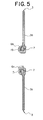
- this separable bottom stop assembly not only allows smooth insertion of a slider (not shown) but also has improved durability because resin on the rear face side opposite to the side where the core thread 4 is attached never peels away upon usage of the fastener.
- Reference numeral 15 in the figure denotes pin holes formed by the pins 8a, 8b. These holes are formed with a predetermined interval in the longitudinal direction in the insert pin 6a and the box pin 6b.
- Fig. 6 shows a condition in which the fastener tape portion 3b with reinforcement tape is inserted into a molding cavity 14a formed in a molding die 14 for molding the insert pin 6a or the box pin 6b of the separable bottom stop assembly 6 integrally with the core portion 7 in the second embodiment of the present invention.
- the sectional shape of the molding cavity 14a of the molding die 14 is not different from an ordinary one as in the first embodiment. Yet, the entire molding cavity 14a is inclined at a predetermined angle to the rear face side of the tape, or rightward in this figure.
- the fastener tape portion 3b with the reinforcement tape inserted into the molding die 14 is not bent around its border with the core portion 7.
- pins 8c, 8d are provided protrusively on both inner walls inside the molding cavity 14a across the core portion 7 so as to oppose each other in the same manner as in the first embodiment. Multiple pairs of the pins 8c, 8d are provided in the tape-length direction of the molding cavity 13a, as in the first embodiment.
- the molding cavity 14a is formed such that it is inclined to the tape main body 3a side of the core portion 7 and the fastener tape portion is held with the pins 8a, 8b without bending the tape portion 3b around its border with the core portion 7, the resin flow-in space at the rear face side of the core portion 7 formed inside the molding cavity 14a is enlarged as in the first embodiment. Consequently, the resin volume at the side opposite to the side where the core thread 4 is attached is increased although the outer shapes of the insert pin 6a and the box pin 6b are not different from the conventional ones, as shown in Fig. 7. Thus, the thickness at the front face side and the rear face side can be made substantially equal. Accordingly, this separable bottom stop assembly not only allows smooth insertion of a slider (not shown) but also has improved durability because resin on the rear face side opposite to the side where the core thread 4 is attached never peels away upon usage of the fastener.
- the fastener tape is bent at the predetermined angle around the border between the core portion 7 and the tape portion 3b when the insert pin 6a and the box pin 6b are formed, as described above.
- special treatment for fixing the bending shape is not carried out on the core portion 7 and the tape main body 3a upon molding.
- the insert pin 6a and the box pin 6b turn to the same condition as shown in Fig. 7, in which the insert pin 6a and the box pin 6b are inclined at the predetermined angle.
Landscapes
- Slide Fasteners (AREA)
- Moulds For Moulding Plastics Or The Like (AREA)
Abstract
Description
Claims (5)
- A slide fastener with a separable bottom stop assembly, having linear fastener element rows (2, 2) along opposing side edges of a pair of fastener tapes (3, 3) and the separable bottom stop assembly (6) comprising an insert pin (6a), a box pin (6b) and a box (6c) made of synthetic resin at an end thereof, said insert pin (6a) and said box pin (6b) being formed integrally by injection molding so as to include core portions (7, 7) adjacent end portions of the fastener element rows (2, 2), and having peripheral shapes allowing themselves to be inserted into element row guide grooves of a slider, being characterized in that
said insert pin (6a) and said box pin (6b) are molded integrally such that the entire insert pin (6a) and the box pin (6b) incline toward rear face sides of the respective tapes (3, 3) from their inner side edges to outer side edges relative to tape planes of the fastener tapes (3, 3), said rear face sides having no core threads (4, 4) of the core portions (7, 7). - A method of manufacturing a slide fastener with a separable bottom stop assembly, including: introducing a core portion (7) adjacent an end portion of each of linear fastener element rows (2, 2) disposed along opposing side edges of a pair of fastener tapes (3, 3) into an injection-molding die (13) for an insert pin (6a) or a box pin (6b); and injecting molten resin into a molding cavity (13a) of said injection-molding die (13) so that the molten resin flows into molding spaces on front and rear face sides of the core portion (7) and is molded integrally around the core portion (7), being characterized by further including:pressing up the core portion (7) disposed in said molding cavity (13a) from the rear face side without a core thread (4) to the front face side of a fastener tape.
- A method of manufacturing a slide fastener with a separable bottom stop assembly according to claim 2, being characterized by further comprising pins (8a) provided protrusively in said cavity (13) for pressing up the core portion (7) from the rear face side to the front face side of the fastener tape.
- A method of manufacturing a slide fastener with a separable bottom stop assembly, including: introducing a core portion (7) adjacent an end portion of each of linear fastener element rows (2, 2) disposed along opposing side edges of a pair of fastener tapes (3, 3) into an injection-molding die (14) for an insert pin (6a) or a box pin (6b); and injecting molten resin into a molding cavity (14a) of said injection-molding die (14) so that the molten resin flows into molding spaces on front and rear face sides of the core portion (7) and is molded integrally around the core portion (7), being characterized by further including:forming a molding cavity (14a) for the insert pin (6a) or the box pin (6b) in said injection-molding die (14) so that said cavity (14a) inclines relative to a core-portion-insertion plane toward a rear face side without a core thread (4) of the fastener tape (3);and maintaining the core portion (7) without bending a tape portion (3b) around its border with the core portion (7) disposed in the molding cavity (14a).
- A method of manufacturing a slide fastener with a separable bottom stop assembly according to claim 4, being characterized by further comprising forming, in said cavity (14a), pins (8c, 8d) for maintaining the core portion (7) without bending the tape portion (3b) around its border with the core portion (7).
Applications Claiming Priority (2)
| Application Number | Priority Date | Filing Date | Title |
|---|---|---|---|
| JP2001390242 | 2001-12-21 | ||
| JP2001390242A JP3736750B2 (en) | 2001-12-21 | 2001-12-21 | Slide fastener with separation fitting and manufacturing method thereof |
Publications (3)
| Publication Number | Publication Date |
|---|---|
| EP1321061A2 true EP1321061A2 (en) | 2003-06-25 |
| EP1321061A3 EP1321061A3 (en) | 2004-06-16 |
| EP1321061B1 EP1321061B1 (en) | 2006-10-18 |
Family
ID=19188355
Family Applications (1)
| Application Number | Title | Priority Date | Filing Date |
|---|---|---|---|
| EP02258444A Expired - Lifetime EP1321061B1 (en) | 2001-12-21 | 2002-12-06 | Slide fastener with separable bottom stop assembly and method of manufacturing the same |
Country Status (8)
| Country | Link |
|---|---|
| US (1) | US6865782B2 (en) |
| EP (1) | EP1321061B1 (en) |
| JP (1) | JP3736750B2 (en) |
| KR (1) | KR100455709B1 (en) |
| CN (1) | CN1223294C (en) |
| DE (1) | DE60215444T2 (en) |
| ES (1) | ES2272643T3 (en) |
| TW (1) | TWI244906B (en) |
Families Citing this family (13)
| Publication number | Priority date | Publication date | Assignee | Title |
|---|---|---|---|---|
| US20100299887A1 (en) * | 2009-06-02 | 2010-12-02 | Yu-Pau Lin | Insertion pin and insertion pin assembly for zipper |
| CN102090762A (en) * | 2011-01-14 | 2011-06-15 | 江苏博豪拉链制造有限公司 | Metal zipper |
| DE112011105270B4 (en) * | 2011-05-24 | 2021-06-24 | Ykk Corporation | Method of forming a stopper and airtight and waterproof zipper |
| WO2013013007A1 (en) | 2011-07-20 | 2013-01-24 | Ykk Corporation | Top stop for slider |
| US9138033B2 (en) | 2013-03-14 | 2015-09-22 | Ykk Corporation | Top stop for slider |
| CN105307533B (en) * | 2013-05-29 | 2018-06-26 | Ykk株式会社 | Slide fastener and injection molding mold with detachable inlay |
| JP6894739B2 (en) * | 2017-03-28 | 2021-06-30 | Ykk株式会社 | Slide fastener |
| US10869526B2 (en) | 2019-01-04 | 2020-12-22 | Target Brands, Inc. | Slide closure with stabilizing fins and associated garment |
| EP4153282B1 (en) | 2020-05-20 | 2026-06-24 | Smokeless.world GmbH | Mobile inhaler for substance delivery |
| CN116113344B (en) * | 2020-10-15 | 2026-02-10 | Ykk株式会社 | Waterproof zipper and its manufacturing method |
| DE112022007668T5 (en) * | 2022-08-12 | 2025-06-18 | Ykk Corporation | Zipper and opening device for a zipper |
| CN116784575A (en) * | 2023-06-02 | 2023-09-22 | 开易(广东)服装配件有限公司 | Zipper processing method and zipper and fabric |
| CN116982791A (en) * | 2023-07-31 | 2023-11-03 | 开易(广东)服装配件有限公司 | Processing methods of zipper products and zipper products |
Family Cites Families (11)
| Publication number | Priority date | Publication date | Assignee | Title |
|---|---|---|---|---|
| FR2055905A5 (en) * | 1969-08-06 | 1971-05-14 | Fflb | |
| DE2010270A1 (en) * | 1970-03-05 | 1971-09-23 | Opti-Holding Ag, Glarus (Schweiz) | Divisible zipper and method of assembling the elements of the divisibility mechanism |
| JPS5315947A (en) * | 1976-07-27 | 1978-02-14 | Yoshida Kogyo Kk | Method of separating*engaging and attaching coil element slide fastener |
| DD143854A1 (en) * | 1979-07-19 | 1980-09-17 | Aloys Apel | DEVICE FOR COMPLETE SEPARATION OF ZIPPERS |
| US4242501A (en) | 1979-08-08 | 1980-12-30 | American Cyanamid Company | Purification of pneumococcal capsular polysaccharides |
| JPS5951809B2 (en) * | 1980-09-10 | 1984-12-15 | ワイケイケイ株式会社 | Slide fastener with release tool |
| JPS57110636A (en) * | 1980-12-26 | 1982-07-09 | Tanaka Kikinzoku Kogyo Kk | Electrical contact material for sealing |
| JPS60195517U (en) * | 1984-06-05 | 1985-12-26 | ワイケイケイ株式会社 | Box mounting structure of slide fastener with releasable fitting |
| JPH02128702A (en) * | 1988-11-08 | 1990-05-17 | Yoshida Kogyo Kk <Ykk> | Slide fastener with opening and fitting device |
| JPH06245806A (en) * | 1993-02-26 | 1994-09-06 | Yoshida Kogyo Kk <Ykk> | Hidden slide fastener mounting method |
| JP3463114B2 (en) * | 1995-04-29 | 2003-11-05 | Ykk株式会社 | Reinforcement tape for slide fastener |
-
2001
- 2001-12-21 JP JP2001390242A patent/JP3736750B2/en not_active Expired - Fee Related
-
2002
- 2002-11-13 TW TW091133278A patent/TWI244906B/en not_active IP Right Cessation
- 2002-11-29 KR KR10-2002-0075366A patent/KR100455709B1/en not_active Expired - Fee Related
- 2002-12-06 EP EP02258444A patent/EP1321061B1/en not_active Expired - Lifetime
- 2002-12-06 DE DE60215444T patent/DE60215444T2/en not_active Expired - Lifetime
- 2002-12-06 ES ES02258444T patent/ES2272643T3/en not_active Expired - Lifetime
- 2002-12-10 US US10/315,368 patent/US6865782B2/en not_active Expired - Fee Related
- 2002-12-18 CN CNB021570205A patent/CN1223294C/en not_active Expired - Lifetime
Also Published As
| Publication number | Publication date |
|---|---|
| DE60215444D1 (en) | 2006-11-30 |
| EP1321061A3 (en) | 2004-06-16 |
| ES2272643T3 (en) | 2007-05-01 |
| TWI244906B (en) | 2005-12-11 |
| EP1321061B1 (en) | 2006-10-18 |
| JP2003180412A (en) | 2003-07-02 |
| US20030115724A1 (en) | 2003-06-26 |
| TW200301090A (en) | 2003-07-01 |
| CN1426711A (en) | 2003-07-02 |
| KR100455709B1 (en) | 2004-11-06 |
| US6865782B2 (en) | 2005-03-15 |
| KR20030052976A (en) | 2003-06-27 |
| CN1223294C (en) | 2005-10-19 |
| JP3736750B2 (en) | 2006-01-18 |
| HK1053410A1 (en) | 2003-10-24 |
| DE60215444T2 (en) | 2007-08-23 |
Similar Documents
| Publication | Publication Date | Title |
|---|---|---|
| US6865782B2 (en) | Slide fastener with separable bottom stop assembly and method of manufacturing the same | |
| CN103068272B (en) | Slide fastener and method for manufacturing same | |
| US7416397B2 (en) | Waterproof slide fastener and apparatus for manufacturing the same | |
| EP1054606B1 (en) | Fastener members, method and apparatus for their fabrication | |
| US11206901B2 (en) | Slide fastener-attached product, element member and manufacturing method of slide fastener-attached product | |
| EP1048239B1 (en) | Slide fastener chain, method and apparatus for forming and thereof | |
| EP1078582B1 (en) | Female engaging member of surface fastener | |
| EP0919152A2 (en) | Separable bottom stop assembly of concealed slide fastener | |
| CN116113344B (en) | Waterproof zipper and its manufacturing method | |
| CN116940261A (en) | Stop for slide fastener and method for manufacturing slide fastener | |
| US4190945A (en) | Method of manufacturing slide fasteners | |
| CA1061092A (en) | Method of manufacturing slide fasteners | |
| CA1097893A (en) | Slide fastener chain | |
| JP3957071B2 (en) | Slide fastener | |
| JPH1033211A (en) | Snap with tape | |
| CN113453580B (en) | Forming surface connector and method for manufacturing the forming surface connector | |
| KR100940065B1 (en) | How to make a slider fastener | |
| JPS6058004B2 (en) | Method for manufacturing stringers for slide fasteners | |
| CN207290718U (en) | Emission forming device | |
| CN116784575A (en) | Zipper processing method and zipper and fabric | |
| WO2021038843A1 (en) | Hook-and-loop fastener and method for manufacturing hook-and-loop fastener | |
| GB2065018A (en) | Manufacture of small plastics articles by injection moulding | |
| JP2004255791A (en) | Filter manufacturing die apparatus, filter manufacturing die apparatus manufacturing method, and filter |
Legal Events
| Date | Code | Title | Description |
|---|---|---|---|
| PUAI | Public reference made under article 153(3) epc to a published international application that has entered the european phase |
Free format text: ORIGINAL CODE: 0009012 |
|
| 17P | Request for examination filed |
Effective date: 20021227 |
|
| AK | Designated contracting states |
Designated state(s): AT BE BG CH CY CZ DE DK EE ES FI FR GB GR IE IT LI LU MC NL PT SE SI SK TR |
|
| AX | Request for extension of the european patent |
Extension state: AL LT LV MK RO |
|
| PUAL | Search report despatched |
Free format text: ORIGINAL CODE: 0009013 |
|
| AK | Designated contracting states |
Kind code of ref document: A3 Designated state(s): AT BE BG CH CY CZ DE DK EE ES FI FR GB GR IE IT LI LU MC NL PT SE SI SK TR |
|
| AX | Request for extension of the european patent |
Extension state: AL LT LV MK RO |
|
| AKX | Designation fees paid |
Designated state(s): DE ES FR GB IT |
|
| GRAP | Despatch of communication of intention to grant a patent |
Free format text: ORIGINAL CODE: EPIDOSNIGR1 |
|
| GRAS | Grant fee paid |
Free format text: ORIGINAL CODE: EPIDOSNIGR3 |
|
| GRAA | (expected) grant |
Free format text: ORIGINAL CODE: 0009210 |
|
| AK | Designated contracting states |
Kind code of ref document: B1 Designated state(s): DE ES FR GB IT |
|
| REG | Reference to a national code |
Ref country code: GB Ref legal event code: FG4D |
|
| REF | Corresponds to: |
Ref document number: 60215444 Country of ref document: DE Date of ref document: 20061130 Kind code of ref document: P |
|
| ET | Fr: translation filed | ||
| REG | Reference to a national code |
Ref country code: ES Ref legal event code: FG2A Ref document number: 2272643 Country of ref document: ES Kind code of ref document: T3 |
|
| PLBE | No opposition filed within time limit |
Free format text: ORIGINAL CODE: 0009261 |
|
| STAA | Information on the status of an ep patent application or granted ep patent |
Free format text: STATUS: NO OPPOSITION FILED WITHIN TIME LIMIT |
|
| 26N | No opposition filed |
Effective date: 20070719 |
|
| PGFP | Annual fee paid to national office [announced via postgrant information from national office to epo] |
Ref country code: ES Payment date: 20091229 Year of fee payment: 8 |
|
| PGFP | Annual fee paid to national office [announced via postgrant information from national office to epo] |
Ref country code: FR Payment date: 20091221 Year of fee payment: 8 Ref country code: GB Payment date: 20091202 Year of fee payment: 8 Ref country code: IT Payment date: 20091217 Year of fee payment: 8 |
|
| PGFP | Annual fee paid to national office [announced via postgrant information from national office to epo] |
Ref country code: DE Payment date: 20091203 Year of fee payment: 8 |
|
| GBPC | Gb: european patent ceased through non-payment of renewal fee |
Effective date: 20101206 |
|
| REG | Reference to a national code |
Ref country code: FR Ref legal event code: ST Effective date: 20110831 |
|
| PG25 | Lapsed in a contracting state [announced via postgrant information from national office to epo] |
Ref country code: FR Free format text: LAPSE BECAUSE OF NON-PAYMENT OF DUE FEES Effective date: 20110103 |
|
| PG25 | Lapsed in a contracting state [announced via postgrant information from national office to epo] |
Ref country code: DE Free format text: LAPSE BECAUSE OF NON-PAYMENT OF DUE FEES Effective date: 20110701 Ref country code: GB Free format text: LAPSE BECAUSE OF NON-PAYMENT OF DUE FEES Effective date: 20101206 |
|
| REG | Reference to a national code |
Ref country code: DE Ref legal event code: R119 Ref document number: 60215444 Country of ref document: DE Effective date: 20110701 |
|
| PG25 | Lapsed in a contracting state [announced via postgrant information from national office to epo] |
Ref country code: IT Free format text: LAPSE BECAUSE OF NON-PAYMENT OF DUE FEES Effective date: 20101206 |
|
| REG | Reference to a national code |
Ref country code: ES Ref legal event code: FD2A Effective date: 20120305 |
|
| PG25 | Lapsed in a contracting state [announced via postgrant information from national office to epo] |
Ref country code: ES Free format text: LAPSE BECAUSE OF NON-PAYMENT OF DUE FEES Effective date: 20101207 |