EP1320486B1 - A novel life-saving device - Google Patents
A novel life-saving device Download PDFInfo
- Publication number
- EP1320486B1 EP1320486B1 EP01971247A EP01971247A EP1320486B1 EP 1320486 B1 EP1320486 B1 EP 1320486B1 EP 01971247 A EP01971247 A EP 01971247A EP 01971247 A EP01971247 A EP 01971247A EP 1320486 B1 EP1320486 B1 EP 1320486B1
- Authority
- EP
- European Patent Office
- Prior art keywords
- buoyant disk
- line
- life
- disk
- saving device
- Prior art date
- Legal status (The legal status is an assumption and is not a legal conclusion. Google has not performed a legal analysis and makes no representation as to the accuracy of the status listed.)
- Expired - Lifetime
Links
- 239000000463 material Substances 0.000 claims description 21
- XLYOFNOQVPJJNP-UHFFFAOYSA-N water Substances O XLYOFNOQVPJJNP-UHFFFAOYSA-N 0.000 claims description 11
- 230000011664 signaling Effects 0.000 claims description 5
- 206010013647 Drowning Diseases 0.000 description 9
- 230000014759 maintenance of location Effects 0.000 description 7
- 230000000694 effects Effects 0.000 description 6
- 208000027418 Wounds and injury Diseases 0.000 description 5
- 230000006378 damage Effects 0.000 description 5
- 230000009189 diving Effects 0.000 description 5
- 208000014674 injury Diseases 0.000 description 5
- -1 polypropylene Polymers 0.000 description 4
- 230000000717 retained effect Effects 0.000 description 4
- 239000004698 Polyethylene Substances 0.000 description 3
- 239000004033 plastic Substances 0.000 description 3
- 229920003023 plastic Polymers 0.000 description 3
- 229920000573 polyethylene Polymers 0.000 description 3
- 238000010276 construction Methods 0.000 description 2
- 230000007423 decrease Effects 0.000 description 2
- 238000005188 flotation Methods 0.000 description 2
- 239000002184 metal Substances 0.000 description 2
- 238000000034 method Methods 0.000 description 2
- 238000009987 spinning Methods 0.000 description 2
- 239000002023 wood Substances 0.000 description 2
- 229920000049 Carbon (fiber) Polymers 0.000 description 1
- 239000004743 Polypropylene Substances 0.000 description 1
- 238000003916 acid precipitation Methods 0.000 description 1
- 230000002411 adverse Effects 0.000 description 1
- 239000004917 carbon fiber Substances 0.000 description 1
- 230000002301 combined effect Effects 0.000 description 1
- 230000001010 compromised effect Effects 0.000 description 1
- 230000000254 damaging effect Effects 0.000 description 1
- 230000005611 electricity Effects 0.000 description 1
- 238000005538 encapsulation Methods 0.000 description 1
- 239000000835 fiber Substances 0.000 description 1
- 230000005484 gravity Effects 0.000 description 1
- 238000002844 melting Methods 0.000 description 1
- 230000008018 melting Effects 0.000 description 1
- VNWKTOKETHGBQD-UHFFFAOYSA-N methane Chemical compound C VNWKTOKETHGBQD-UHFFFAOYSA-N 0.000 description 1
- 230000008520 organization Effects 0.000 description 1
- 230000000149 penetrating effect Effects 0.000 description 1
- 229920001155 polypropylene Polymers 0.000 description 1
- 230000005855 radiation Effects 0.000 description 1
- 238000011084 recovery Methods 0.000 description 1
- 230000002787 reinforcement Effects 0.000 description 1
- 230000000087 stabilizing effect Effects 0.000 description 1
Images



Classifications
-
- B—PERFORMING OPERATIONS; TRANSPORTING
- B63—SHIPS OR OTHER WATERBORNE VESSELS; RELATED EQUIPMENT
- B63C—LAUNCHING, HAULING-OUT, OR DRY-DOCKING OF VESSELS; LIFE-SAVING IN WATER; EQUIPMENT FOR DWELLING OR WORKING UNDER WATER; MEANS FOR SALVAGING OR SEARCHING FOR UNDERWATER OBJECTS
- B63C9/00—Life-saving in water
- B63C9/08—Life-buoys, e.g. rings; Life-belts, jackets, suits, or the like
-
- B—PERFORMING OPERATIONS; TRANSPORTING
- B63—SHIPS OR OTHER WATERBORNE VESSELS; RELATED EQUIPMENT
- B63C—LAUNCHING, HAULING-OUT, OR DRY-DOCKING OF VESSELS; LIFE-SAVING IN WATER; EQUIPMENT FOR DWELLING OR WORKING UNDER WATER; MEANS FOR SALVAGING OR SEARCHING FOR UNDERWATER OBJECTS
- B63C9/00—Life-saving in water
- B63C9/26—Cast or life lines; Attachments thereto; Containers therefor; Rescue nets or the like
Definitions
- the invention relates to floatation devices for aquatic rescue more particularly to a hand thrown life saving device.
- the rule recommends that if the drowning victim cannot be reached, or if a flotation aid or retrieval device cannot be thrown to the drowning victim that the rescuer should not attempt an open water rescue.
- the rescuer must be able to provide an additional means of buoyancy and establish stability to the victim to be able to effect recovery without placing themselves in jeopardy.
- a device be deployed to the victim.
- Several devices have been developed that can be tossed or thrown to the victim to facilitate rescue.
- Desirable features of a water rescue device which may prove critical under certain circumstances include the following: sufficient buoyancy, sufficient reach upon deployment and redeployment, compact and easy to use, does not dive during rescue retrieval, constructed of materials t hat are not likely to cause injury to the victim and may be easily gripped by the victim and rescuer, constructed of materials that can withstand rough handling and impact without loosing functionality. None of the currently available rescue devices incorporate or are able to incorporate all of the aforementioned features.
- the line throw bag is designed to provide an immediate link with the victim in the form of a rope or line that can be retracted to effect retrieval and rescue.
- the line throw bag is designed to provide an immediate link with the victim in the form of a rope or line that can be retracted to effect retrieval and rescue.
- the device meets some of the desired features for a life saving device it has poor buoyancy and is difficult to redeploy if the first attempt at reaching the victim fails.
- the device may also cause injury if it hits the victim during rescue.
- the standard life ring and seat cushion/floatation devices meet many of the desirable features for a life saving device, however they fail in other critical aspects.
- the devices have substantially less reach than flying disk rescue devices. Often these devices do not have a retrieval line that enables a rescuer to retrieve and redeploy the device if the victim is not reached or is missed on the first throw or toss.
- some standard life rings include an attached retrieval line, the life ring may have the tendency to dive during retrieval, which jeopardizes the safety of the victim and slows retrieval time.
- Flying rescue disks with retrieval line retention and deployment features on or about the outside perimeter of the disk like those described in United States patent 5,562,512 and 5,895,299 also meet some of the desirable features of a life saving device, however, they suffer from lack of aerodynamic efficiency due to the interference caused by the location of the line retention and deployment features in aerodynamic areas critical for performance.
- the disks are often made of hard rigid materials to retain the line and to add mass and rigidity to overcome reach limitations due to poor aerodynamics.
- their buoyancy is generally poor and their potential for injuring the victim is high because of their hard body construction.
- Some flying rescue disks incorporate a hollow flotation compartment defined by a hard plastic encapsulation to increase buoyancy, unfortunately they can be damaged by rough handling or impact, which may allow water to flood the compartment or otherwise decrease the disk's functionality.
- the retrieval lines of these devices are affixed to their leading edge and consequently during rescue the devices have a tendency to dive under water upon retrieval jeopardizing the safety of the victim and extending retrieval time.
- the retrieval line should be partially rewound around the outer perimeter to allow for free rotation of the disk, which may further delay rescue time.
- a life saving device that is compact and easy to use, may be quickly deployed at distances of approximately 30.48 mm (100 feet), may be quickly retrieved and redeployed, is sufficiently buoyant to stabilize the drowning victim and constructed of a gripable material that is not likely to cause injury and can withstand rough handling and impact without loosing functionality.
- a further desirable characteristic is the resistance of the device to dive during retrieval.
- the life-saving device comprises a buoyant disk having a top side, a bottom side, a leading edge and a cavity on the bottom side along and adjacent to the leading edge, the cavity having an inner side generally parallel to the leading edge, the inner side having an upper edge and a lower edge and a length of line affixed through and about the center of the buoyant disk generally parallel to the leading edge and disposed around the inner side of the cavity.
- the life-saving device comprises a buoyant disk having a top side, a bottom side, a leading edge and a cavity on the bottom side along and adjacent to the leading edge, the cavity having an inner side distant from the center of the buoyant disk and an outer side more distant from the center of the buoyant disk than the inner side and a base plate having an upper surface, a lower surface and a diameter less than that of the buoyant disk and overlapping the cavity, the upper surface comprising a hollow tube portion projecting perpendicular from the center of the upper surface, the hollow tube portion affixed through the center of the buoyant disk having a diameter able to accept a line and of a length generally equal to the thickness of the buoyant disk.
- the life-saving device comprises a buoyant disk having a top side, a bottom side, a leading edge and a cavity disposed on the bottom side along and generally adjacent to the leading edge of the buoyant disk having an inner side distant from the center of the buoyant disk and an outer side more distant from the center of the buoyant disk than the inner side, the cavity able to accept a length of line disposed around the inner side of the cavity; a base plate having an upper surface, a lower surface and a diameter less than that of the buoyant disk and overlapping the cavity, the upper surface affixed to the bottom side of the buoyant disk; and a hollow tube affixed through the center of the buoyant disk and the base plate having a diameter able to accept a line and of a length generally equal to the combined thickness of the buoyant disk and the base plate.
- the buoyant disk is made of a semi-rigid flexible material having a generally aerodynamic profile such that lift is generated during flight and that may be domed on the top side, the bottom side or on both the top side and the bottom side.
- the buoyant disk may further comprise a flange on the lower edge of the inner side of the cavity extending generally perpendicular from the inner side toward the leading edge of the buoyant disk, a reflective surface on the top side or the bottom side and/or a leading edge having a different density than the remainder of the buoyant disk.
- the life-saving device may further comprise; a length of line affixed to the buoyant disk such that when in use a domed side of the buoyant disk is in contact with the surface of the water to prevent the device from diving; a hollow tube be affixed through and about the center of the buoyant disk generally parallel to the leading edge and having a diameter able to accept a line and of a length generally equal to the thickness of the buoyant disk; a length of line, one end of which is generally affixed through or within the hollow tube; a base plate having an upper surface and a lower surface, the upper surface affixed to the bottom side of the buoyant disk, the base plate having a diameter less than the buoyant disk and overlapping the cavity; a reflective surface on the lower surface of the base plate; a balance ring that may be affixed to embedded in or implanted within the bottom side of the buoyant disk generally adjacent to the leading edge; and/or an audible signaling device embedded within the buoyant disk.
- the buoyant disk of the present invention has a top side, a bottom side and a leading edge.
- the sides and leading edge of the disk are designed to be aerodynamic creating a single airfoil such that under normal conditions air can flow smoothly around the disk.
- the top side of the disk is generally domed.
- the bottom side may be flat, concave or domed.
- the buoyant disk has an asymmetric profile. The purpose of having an asymmetrical profile is to provide lift as it moves through the air.
- the leading edge as used herein refers to the surface of the buoyant disk that is generally perpendicular to the top and bottom sides of the disk.
- the leading edge has an upper end and a lower end wherein the lower end protrudes outward further than the upper end to contour the flow of air around the disk during use.
- the buoyant disk has a diameter of about 365.6 mm (14.0 inches) to about 5.08 mm (20.0 inches).
- the disk is about 381 mm (15.0 inches) to about 457.2 mm (18.0 inches) and most preferably about 419.1 mm (16.5 inches).
- the disk has a thickness of about 50.8 mm (2.0 inches) to about 12.7 mm (5.0 inches).
- the thickness is from about 63.5 mm (2.5 inches) to about 101.6 mm (4.0 inches) and most preferably about 76.2 mm (3.0 inches). It is generally circular in shape and may be made of a flexible semi-rigid material such as for example expandable polypropylene or polyethylene.
- the buoyant disk also comprises a cavity on the bottom side along and adjacent to the leading edge in which a length of line may be retained.
- This cavity may be provided in a variety of orientations. In a preferred orientation the cavity forms a groove along and adjacent to the leading edge within the bottom side of the buoyant disk. Preferably this groove is positioned close to the leading edge. This positioning allows the spinning of the device to exert a sufficient gyroscopic effect on a retained line to aid in easy deployment of the line during use. It also allows the retained line to adds mass to the perimeter of the device increasing its stability and rotation as it moves through the air, provides a gyroscopic leveling effect to the device during use and reduces, the binding and/or kinking of the line during deployment.
- the groove has an inner side distant from the center of the buoyant disk and an outer side more distant from the center of the buoyant disk than the inner side. Both the inner and outer sides of the cavity being generally perpendicular to the top side of the buoyant disk with the inner side of the cavity able to accept a length of line.
- the distance between the inner side and outer side will depend on the length of line to be disposed around the inner side of the cavity and the thickness of the line used. This distance may be from about 2.7mm (0.5 inches) to about 101.6mm (4 inches). Preferably this distance is about 63.5mm (2.5 inches) when approximately 30.48mm (100 feet) of line having diameter 4.76mm (3/16 inches) is used.
- the depth of the cavity will also depend on the length of line to be disposed around the inner side of the cavity and the thickness of the line used. This depth may be from about 19.05mm (3/4 inches) to about 38.1 mm (1.5 inches). Preferably the depth is about 25.4 mm (1.0 inch) when approximately 30.48 mm (100 feet) of line having diameter 4.76mm (3/16 inches) is used.
- the inner side has an upper edge adjacent to the top side of the buoyant disk and a lower edge more distant from the top side of the buoyant disk than the upper edge.
- the distance between the upper edge and lower edge will depend on the length and diameter of line to be disposed around the inner side of the cavity and desired center of gravity of the buoyant disk. This distance ma be from about 12.7mm (0.5 inches) to about 38.1mm (1.5 inches). Preferably this distance is about 25.4mm (1.0 inch) when approximately 30.48mm (100 feet) of line having diameter 4.76mm (3/16 inches) is used.
- the lower edge may further comprise a flange generally perpendicular to and adjacent to the inner side of the cavity and extending toward the leading edge to assist in retention of a line within the cavity when not in use and to allow easy deployment of the line during use.
- the distance the flange extends from the inner side toward the leading edge will also depend on the length and diameter of line to be disposed around the inner side of the cavity. Preferably this distance is from about 25% to about 75% of the distance from the inner side to the outer side, most preferably this distance is about 50%. More particularly the distance the flange extends from the inner side of the cavity is from about 0.2 mm (0.0078 inches) to about 50.8 mm (2.0 inches).
- this distance is from about 12.7 mm (0.5 inches) to about 38.1 mm (1.5 inches), most preferably 9.05 mm (0.75 inches) when approximately 30.48 mm (100 feet) of line having diameter 476 mm (3/6 inches) is used.
- the thickness of the flange is such that it is able to support and secure a line for deployment when the device is not in use and not be torn from the inner side when the device is deployed.
- the cavity sides may be generally perpendicular to the top side of the buoyant disk and may have perpendicular, angled, or any combination of perpendicular and angled aspects that allow the line to be maintained within the cavity securely when not in use and deployed with ease during use.
- the bottom edge is farther from the center of the buoyant disk than the upper edge forming a sloped surface allowing the line to be retained around the inner side and free to deploy during use.
- the inner side of the cavity extends below the leading edge of the buoyant disk. This distance may be up to about 12.7 mm (0.5 inches). Preferably this distance is as small as possible.
- the buoyant disk may have an orifice or hole penetrating through the buoyant disk from side to side around or about its' center.
- the orifice is large enough to accept a line and preferably of a diameter sufficient to allow the line to move freely once affixed within or through the orifice.
- the line maybe inserted from the top side or the bottom side of the buoyant disk.
- Preferably the line is inserted on a side having a domed shape and secured on the opposite side so that in use a domed side is in contact with the surface of the water upon retrieval.
- the line may be affixed within or secured through the orifice by an adapter of a size and shape that prevents the line from exiting the orifice and allowing free movement of the line in the orifice.
- One or more adapters may be placed on the line, preferably the adapter is placed on the end of the line opposite a domed surface. However if both sides are domed it is preferably secured on the side from which the line is deployed, most preferably the bottom side of the buoyant disk. In another preferred embodiment an adapter is secured to the line on both sides of the buoyant disk maintaining the disk in one location along the line.
- Adapters that may be used to affix the line within or though the orifice include for example, a knot in the line, enlargement of the end of the line, such as for example by melting the line to form a mass having a diameter larger than the orifice, or a stop secured to the end of the line, such as for example a washer having a diameter larger than the orifice.
- a stop When a stop is secured to the end of the line the stop may be of a variety of shapes or combination of shapes including thin or flat, cone-shaped, T-shaped or hat-shaped and may be made of a variety of materials including for example plastic, carbon fiber, metal, and wood.
- the stop is of a shape that does not interfere with the free movement of the line within the orifice once it is secured to the end of the line.
- the buoyant device may also have a groove provided in the top side of the buoyant disk leading generally from the orifice at or about the center of the disk up to and may include the leading edge.
- the general purpose of the groove is to reduce drag and maintain the aerodynamic surface of the disk by incorporating that portion of the line between the orifice and the leading edge into the top side of the disk.
- a variety of types of grooves may be provided, preferably the groove is a press-fit groove of a size able to accept the line affixed in or through the orifice of the buoyant disk that will easily release the line after deployment.
- the material comprising the leading edge of the buoyant disk may be of a higher density than the remainder of the buoyant providing a gyroscopic effect in flight stabilizing the device in use.
- the leading edge may also have a density similar to the remainder of the buoyant disk and further comprise a balance ring of high density material affixed to, embedded in or implanted within the bottom side of the buoyant disk adjacent to the leading edge.
- the buoyant disk may further comprise a plurality of apertures in its' top or bottom sides adjacent to the leading edge able to accept weighted balance plugs.
- the balance ring and plugs may be made of a variety of materials that generally have a greater density than the material from which the buoyant disk is constructed. Such materials include for example, plastics, wood and metal.
- the buoyant disk may also be provided with a surface that is brightly colored or reflective on the top side, the bottom side, the leading edge or any combination of these surfaces including providing the entire buoyant disk with a such a surface for easy identification during rescue.
- the buoyant disk may also be provided with a cushioned leading edge to soften impact and prevent injury to a drowning during rescue.
- the base plate of the present invention has an upper surface and a lower surface with a diameter generally less than that of the buoyant disk and overlapping the cavity on the bottom side of the buoyant disk.
- the base plate overlaps the cavity to assist in retention of a line within the cavity when not in use and to allow easy deployment of the line during use.
- the amount of overlap will depend on the length and diameter of line to be disposed around the inner side of the cavity. Preferably this distance is from about 25% to about 75% of the distance from the inner side to the outer side, most preferably this distance is about 50%.
- the base plate may be provided in a variety of shapes including for example flat or domed and has a thickness generally less than the buoyant disk.
- the base plate may further comprise an orifice at or about the center and in line with the orifice in the buoyant disk.
- the upper surface may be affixed to the bottom side of the buoyant disk.
- the upper surface may also include a hollow tube portion projecting perpendicular from the center of the upper surface.
- the hollow tube portion has a diameter able to accept a line, is of a length generally equal to the thickness of the buoyant disk and is generally inserted or affixed through and about the center of the buoyant disk.
- the hollow tube portion may be a variety of shapes including for example cylindrical, cone shaped, hat-shaped or any combination of shapes including cylindrical and cone-shaped or a number of cylindrical shapes of different diameters.
- the base plate has a diameter of about 2.54 mm (10.0 inches) to about 3.81mm (15.0) inches and a thickness of about 8.47mm (1/3 inches) to about 6.35mm (1/4 inches). It is preferably circular in shape and made of a flexible material such as for example polyethylene.
- the hollow tube of the present invention is affixed through and about the center of the buoyant disk or through the buoyant disk and base plate. It has a length generally equal to the thickness of the buoyant disk or the combined thickness of the buoyant disk and the base plate and a diameter able to accept a line and allow free movement of the line within the hollow tube.
- the hollow tube may provide rigidity and reinforcement to the buoyant disk, and provide a low friction surface for a line.
- the hollow tube may be provided in a variety of shapes including cylindrical, cone shaped, hat-shaped or any combination of shapes including cylindrical and cone-shaped or a number of cylindrical shapes of different diameters.
- the hollow tube is generally hat-shaped comprising a cylindrical or cone-shaped tube portion and a base portion generally perpendicular to the tube portion. If the tube portion is cone-shaped the base portion is preferably positioned at the larger opening of the cone-shaped tube portion.
- the base portion may have a generally circular shape with a diameter generally less than the diameter of the base plate. This diameter may be from about 25.4 mm (1.0 inches) to about 152.4mm (6.0 inches). Preferably the diameter is from about 50.8mm (2.0 inches) to about 101.6mm (4.0 inches) and most preferably about 76.2mm (3.0 inches).
- the hollow tube When the hollow tube is provided in this shape it may be inserted through the buoyant disk such that the base portion may be affixed and secured generally flush against the bottom side of the buoyant disk or the lower surface of the base plate. Once affixed within the device a line may be secured within or through the hollow tube.
- the hollow tube has a diameter of about 6.35 mm (0.25 inches) to about 12.7 mm (0.5 inches), and a length of about 50.8 mm (2.0 inches) to about 127 mm (5.0 inches). Preferably this length is equal to the combined thickness of the buoyant disk or the buoyant disk and base plate. It is generally circular in shape and made of a material such as for example polyethylene.
- the line that may be used with the present invention may be any commercially available line having a diameter of from about 9.525 mm (3/8 inches) to about 12.7 mm (1/2 inches), constructed of a material having the equivalent of 90.72 kg (200 pound) test line, generally of light weight, easily gripped surface and made of a synthetic or natural fiber.
- the line is made of a material that is generally water-resistant and buoyant.
- the signaling device may be any commercially available device that elicits a sound or light when operated by the user.
- the device may be affixed to, embedded in or implanted within the buoyant disk.
- a number of audible devices may be utilized with the present invention including those that are strictly mechanical, those that require electricity to operate and those operated by compressed air.
- the device is a whistle. If a light signaling device is utilized it is preferably a high wattage strobe type.
- a life-saving device comprising a buoyant disk having a top side, a bottom side, a leading edge and a cavity on the bottom side along and adjacent to the leading edge.
- the cavity has an inner side generally parallel to the leading edge and distant from the center of the buoyant disk.
- a length of line is affixed to the buoyant disk and disposed around the inner side of the cavity.
- the line is preferably affixed to the buoyant disk through an orifice about the center of the disk which is oriented approximately parallel to the leading edge.
- the diameter of the orifice is preferably larger than the diameter of the line so that the line may move freely within the orifice.
- the line is generally inserted through this orifice from the top side of the buoyant disk and fitted with an adapter to secure the line to the buoyant disk.
- the line is approximately 30.48mm (100 feet) in length and secured at the bottom sides of the buoyant disk.
- the top side of the buoyant disk is preferably domed to prevent the device from diving during rescue retrieval.
- a life-saving device comprising a buoyant disk having a top side, a bottom side, a leading edge and a cavity on the bottom side along and adjacent to the leading edge.
- the cavity generally has an inner side distant from the center of the buoyant disk and an outer side more distant from the center of the buoyant disk than the inner side.
- the device further includes a base plate having an upper surface and a lower surface and a diameter generally less than that of the buoyant disk and overlapping the cavity.
- the base plate preferably overlaps the cavity approximately 50% to allow retention of the line when the device is stored and for rapid deployment of the line during use.
- the upper surface of the base plate preferably has a hollow tube portion projecting perpendicular from its center.
- the hollow tube portion has a diameter able to accept a line and of a length generally equal to the thickness of the buoyant disk.
- the upper side of the base plate is affixed to the bottom side of the buoyant disk while the hollow tube portion is simultaneously affixed through and about the center of the buoyant disk.
- the base plate is preferably flat having a cone shaped hollow tube projecting generally from the upper surface.
- a length of line is drawn through the smaller end of the hollow tube portion and an adapter is affixed to the end that allows the line to move freely within the tube and to prevent the line from exiting.
- the line is approximately 30.48 mm (100 feet) in length and the top side of the buoyant disk is preferably domed to prevent the device from diving during rescue retrieval.
- the lower surface of the base plate is preferably provided with a reflective surface for easy identification during rescue.
- a life-saving device comprising a buoyant disk having a top side, a bottom side, a leading edge and a cavity disposed on the bottom side along and generally adjacent to the leading edge of the buoyant disk.
- the cavity has an inner side distant from the center of the buoyant disk and an outer side more distant from the center of the buoyant disk than the inner side.
- the cavity is able to accept a length of line disposed around the inner side.
- This device further comprises a base plate having an upper surface and a lower surface.
- the lower surface of the base plate is preferably domed.
- the diameter of the base plate is generally less than that of the buoyant disk and overlaps the cavity approximately 50% to allow retention of the line when the device is stored and for rapid deployment of the line during use.
- the upper surface of the base plate is affixed to the bottom side of the buoyant disk.
- a hollow tube is affixed to and secured through the center of the buoyant disk and the base plate.
- the hollow tube has a diameter able to accept a line such that the line may move freely within the tube during use and of a length generally equal to the combined thickness of the buoyant disk and the base plate.
- a line approximately 30.48mm (100 feet) in length is drawn through the hollow tube from top side of the buoyant disk and an adapter is affixed to the end to prevent the line from exiting the tube during use.
- the line is disposed around the inner side of the cavity prior to use.
- the top side of the buoyant disk is preferably domed to prevent the device from diving during rescue retrieval and has a press-fit groove of a size able to accept the line affixed in or through the hollow tube that will easily release the line after deployment.
- the lower surface of the base plate and the top side of the buoyant disk are preferably provided with a reflective surface for easy identification during rescue.
- a whistle is embedded in the top side of the buoyant disk so that the victim may provide an audible signal during rescue.
- the device of the present invention stores and deploys the line disposed around the inner side of the cavity from the bottom side of the device.
- This orientation provides several advantages over currently available commercial devices. In particular this orientation allows surfaces that are aerodynamically critical for optimal flight to be designed with minimal interference from the storage and deployment area, specifically for the leading edge. Since more efficient aerodynamic design is possible with bottom side storage and deployment of the line the device may be thrown greater distances. Hard surfaced rigid materials have been used to improve flight characteristics that are compromised from deployment of the line from critical aerodynamic surfaces, unfortunately these hard rigid surfaces can be easily damaged or cause injury to a victim on impact. For improved aerodynamic design, the device of the present invention can be made with surfaces and materials that are soft and flexible and can be thrown as far as comparable commercially available devices designed with hard rigid surfaces and materials. Another advantage of this orientation is that it helps shelter the line from environmentally damaging effects that may affect the integrity or performance of the line such as ultra violet radiation, tree sap, and acid rain.
- the line When in use the line is partially unwound from the inner side of the cavity and anchored by the user.
- the device may then be thrown to the drowning victim by a variety of techniques identical to and similar to those used when throwing a disk (e.g. a Frisbee TM ) through the air.
- the spinning of the disk assists and causes the remainder of the line to be deployed during flight.
- the aerodynamic shape of the buoyant disk provides lift when thrown allowing the device to travel distance up to and exceeding 30.48mm (100 feet).
- the device When the device lands in the water it is preferable that it be in the vicinity of the drowning victim's grasp. However, if the device is thrown past or past and to the side of the victim the user may then manipulate the device so that it reaches the victim.
- This may be accomplished by moving to the left or the right while retracting the device such that the buoyant disk moves within the reach of the victim. If the device falls short of the victim the user may retrieve the device by retracting the line and deploying the device a second time without rewinding the line. Retrieval of the device may be accomplished much faster than commercially available devices because of the combined effects of the domed surface and the center pull construction. These two features allow the device to skim across the water without diving like other commercially available devices.
- the line may be fitted into a groove made in the top side surface of the buoyant disk to secure the line during flight.
- the groove is large enough to hold the line tightly during deployment but releases the line once the line is retracted through the water.
- buoyant disk allows for easy grasping and retention of grip by the victim during rescue.
- the buoyant disk is grasped and held close to the victims' chest during retraction providing sufficient buoyancy and stability to effect rescue.
Landscapes
- Mechanical Engineering (AREA)
- Ocean & Marine Engineering (AREA)
- Engineering & Computer Science (AREA)
- Indicating And Signalling Devices For Elevators (AREA)
- Emergency Lowering Means (AREA)
- Sink And Installation For Waste Water (AREA)
- Electrical Discharge Machining, Electrochemical Machining, And Combined Machining (AREA)
- Other Liquid Machine Or Engine Such As Wave Power Use (AREA)
- Professional, Industrial, Or Sporting Protective Garments (AREA)
- Cyclones (AREA)
- Paper (AREA)
- Manufacture, Treatment Of Glass Fibers (AREA)
- Toys (AREA)
Abstract
Description
- The invention relates to floatation devices for aquatic rescue more particularly to a hand thrown life saving device.
- In 1998 the World Health Organization reported 119,000 drownings worldwide with approximately 5,000 of those occurring in the United States alone according to the American Red Cross. Data collected by the International Lifesaving Association indicates that most of these drownings occurred within 60 seconds and according to the statistics of the National Safety Council there has been no significant decline in the fatality rate for drowning victims over the past two decades.
- The American Red Cross advises that the untrained and inexperienced would-be rescuer follow the rule "Reach, Throw, Don't Go". The rule recommends that if the drowning victim cannot be reached, or if a flotation aid or retrieval device cannot be thrown to the drowning victim that the rescuer should not attempt an open water rescue. For these types of non-professional rescue attempts the rescuer must be able to provide an additional means of buoyancy and establish stability to the victim to be able to effect recovery without placing themselves in jeopardy. In circumstances where the victim cannot be physically reached by the rescuer it is recommended that a device be deployed to the victim. Several devices have been developed that can be tossed or thrown to the victim to facilitate rescue. Desirable features of a water rescue device which may prove critical under certain circumstances include the following: sufficient buoyancy, sufficient reach upon deployment and redeployment, compact and easy to use, does not dive during rescue retrieval, constructed of materials t hat are not likely to cause injury to the victim and may be easily gripped by the victim and rescuer, constructed of materials that can withstand rough handling and impact without loosing functionality. None of the currently available rescue devices incorporate or are able to incorporate all of the aforementioned features.
- Commercially available devices include the line throw bag, the standard life ring or seat cushion/floatation device and the flying disk. The line throw bag is designed to provide an immediate link with the victim in the form of a rope or line that can be retracted to effect retrieval and rescue. Unfortunately while the device meets some of the desired features for a life saving device it has poor buoyancy and is difficult to redeploy if the first attempt at reaching the victim fails. In addition the device may also cause injury if it hits the victim during rescue.
- Likewise the standard life ring and seat cushion/floatation devices meet many of the desirable features for a life saving device, however they fail in other critical aspects. The devices have substantially less reach than flying disk rescue devices. Often these devices do not have a retrieval line that enables a rescuer to retrieve and redeploy the device if the victim is not reached or is missed on the first throw or toss. Although some standard life rings include an attached retrieval line, the life ring may have the tendency to dive during retrieval, which jeopardizes the safety of the victim and slows retrieval time.
- Flying rescue disks with retrieval line retention and deployment features on or about the outside perimeter of the disk like those described in United States patent 5,562,512 and 5,895,299 also meet some of the desirable features of a life saving device, however, they suffer from lack of aerodynamic efficiency due to the interference caused by the location of the line retention and deployment features in aerodynamic areas critical for performance. The disks are often made of hard rigid materials to retain the line and to add mass and rigidity to overcome reach limitations due to poor aerodynamics. In addition, their buoyancy is generally poor and their potential for injuring the victim is high because of their hard body construction. Some flying rescue disks incorporate a hollow flotation compartment defined by a hard plastic encapsulation to increase buoyancy, unfortunately they can be damaged by rough handling or impact, which may allow water to flood the compartment or otherwise decrease the disk's functionality. In addition, the retrieval lines of these devices are affixed to their leading edge and consequently during rescue the devices have a tendency to dive under water upon retrieval jeopardizing the safety of the victim and extending retrieval time. Also, for a more effectively redeployment of these devices, the retrieval line should be partially rewound around the outer perimeter to allow for free rotation of the disk, which may further delay rescue time.
- Consequently, there is a need in the industry for a life saving device that is compact and easy to use, may be quickly deployed at distances of approximately 30.48 mm (100 feet), may be quickly retrieved and redeployed, is sufficiently buoyant to stabilize the drowning victim and constructed of a gripable material that is not likely to cause injury and can withstand rough handling and impact without loosing functionality. A further desirable characteristic is the resistance of the device to dive during retrieval.
- In accordance with the present invention a novel life-saving device is provided. In one embodiment, the life-saving device comprises a buoyant disk having a top side, a bottom side, a leading edge and a cavity on the bottom side along and adjacent to the leading edge, the cavity having an inner side generally parallel to the leading edge, the inner side having an upper edge and a lower edge and a length of line affixed through and about the center of the buoyant disk generally parallel to the leading edge and disposed around the inner side of the cavity.
- In another embodiment, the life-saving device comprises a buoyant disk having a top side, a bottom side, a leading edge and a cavity on the bottom side along and adjacent to the leading edge, the cavity having an inner side distant from the center of the buoyant disk and an outer side more distant from the center of the buoyant disk than the inner side and a base plate having an upper surface, a lower surface and a diameter less than that of the buoyant disk and overlapping the cavity, the upper surface comprising a hollow tube portion projecting perpendicular from the center of the upper surface, the hollow tube portion affixed through the center of the buoyant disk having a diameter able to accept a line and of a length generally equal to the thickness of the buoyant disk.
- In yet another embodiment, the life-saving device comprises a buoyant disk having a top side, a bottom side, a leading edge and a cavity disposed on the bottom side along and generally adjacent to the leading edge of the buoyant disk having an inner side distant from the center of the buoyant disk and an outer side more distant from the center of the buoyant disk than the inner side, the cavity able to accept a length of line disposed around the inner side of the cavity; a base plate having an upper surface, a lower surface and a diameter less than that of the buoyant disk and overlapping the cavity, the upper surface affixed to the bottom side of the buoyant disk; and a hollow tube affixed through the center of the buoyant disk and the base plate having a diameter able to accept a line and of a length generally equal to the combined thickness of the buoyant disk and the base plate.
- In one aspect of the present invention the buoyant disk is made of a semi-rigid flexible material having a generally aerodynamic profile such that lift is generated during flight and that may be domed on the top side, the bottom side or on both the top side and the bottom side.
- In other aspects of the present invention the buoyant disk may further comprise a flange on the lower edge of the inner side of the cavity extending generally perpendicular from the inner side toward the leading edge of the buoyant disk, a reflective surface on the top side or the bottom side and/or a leading edge having a different density than the remainder of the buoyant disk.
- In still other aspects of the invention the life-saving device may further comprise; a length of line affixed to the buoyant disk such that when in use a domed side of the buoyant disk is in contact with the surface of the water to prevent the device from diving; a hollow tube be affixed through and about the center of the buoyant disk generally parallel to the leading edge and having a diameter able to accept a line and of a length generally equal to the thickness of the buoyant disk; a length of line, one end of which is generally affixed through or within the hollow tube; a base plate having an upper surface and a lower surface, the upper surface affixed to the bottom side of the buoyant disk, the base plate having a diameter less than the buoyant disk and overlapping the cavity; a reflective surface on the lower surface of the base plate; a balance ring that may be affixed to embedded in or implanted within the bottom side of the buoyant disk generally adjacent to the leading edge; and/or an audible signaling device embedded within the buoyant disk.
-
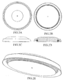
- FIG. 1 is the life-saving device with a length of line. A is a top view of the device, B is a bottom view of the device, C is a side view of the device, D is a cross-sectional view of the device and E is a perspective view of the device.
- FIG. 2 is the life-saving device having a flange. A is a top view of the device, B is a bottom view of the device, C is a side view of the device, D is a cross-sectional view of the device and E is a perspective view of the device.
- FIG. 3 is the life-saving device having a base plate comprising a hollow tube portion projecting perpendicular from the center of the upper surface of the base plate. A is a top view of the device, B is a bottom view of the device, C is a side view of the device, D is a cross-sectional view of the device and E is a perspective view of the device.
- FIG. 4 is the life saving device having a base plate and a hollow tube. A is a top view of the device, B is a bottom view of the device, C is a side view of the device, D is a cross-sectional view of the device and E is a perspective view of the device.
- The buoyant disk of the present invention has a top side, a bottom side and a leading edge. The sides and leading edge of the disk are designed to be aerodynamic creating a single airfoil such that under normal conditions air can flow smoothly around the disk. The top side of the disk is generally domed. The bottom side may be flat, concave or domed. Preferably the buoyant disk has an asymmetric profile. The purpose of having an asymmetrical profile is to provide lift as it moves through the air. The leading edge as used herein refers to the surface of the buoyant disk that is generally perpendicular to the top and bottom sides of the disk. Preferably the leading edge has an upper end and a lower end wherein the lower end protrudes outward further than the upper end to contour the flow of air around the disk during use. The buoyant disk has a diameter of about 365.6 mm (14.0 inches) to about 5.08 mm (20.0 inches). Preferably the disk is about 381 mm (15.0 inches) to about 457.2 mm (18.0 inches) and most preferably about 419.1 mm (16.5 inches). The disk has a thickness of about 50.8 mm (2.0 inches) to about 12.7 mm (5.0 inches). Preferably the thickness is from about 63.5 mm (2.5 inches) to about 101.6 mm (4.0 inches) and most preferably about 76.2 mm (3.0 inches). It is generally circular in shape and may be made of a flexible semi-rigid material such as for example expandable polypropylene or polyethylene.
- The buoyant disk also comprises a cavity on the bottom side along and adjacent to the leading edge in which a length of line may be retained. This cavity may be provided in a variety of orientations. In a preferred orientation the cavity forms a groove along and adjacent to the leading edge within the bottom side of the buoyant disk. Preferably this groove is positioned close to the leading edge. This positioning allows the spinning of the device to exert a sufficient gyroscopic effect on a retained line to aid in easy deployment of the line during use. It also allows the retained line to adds mass to the perimeter of the device increasing its stability and rotation as it moves through the air, provides a gyroscopic leveling effect to the device during use and reduces, the binding and/or kinking of the line during deployment. The groove has an inner side distant from the center of the buoyant disk and an outer side more distant from the center of the buoyant disk than the inner side. Both the inner and outer sides of the cavity being generally perpendicular to the top side of the buoyant disk with the inner side of the cavity able to accept a length of line. The distance between the inner side and outer side will depend on the length of line to be disposed around the inner side of the cavity and the thickness of the line used. This distance may be from about 2.7mm (0.5 inches) to about 101.6mm (4 inches). Preferably this distance is about 63.5mm (2.5 inches) when approximately 30.48mm (100 feet) of line having diameter 4.76mm (3/16 inches) is used. The depth of the cavity will also depend on the length of line to be disposed around the inner side of the cavity and the thickness of the line used. This depth may be from about 19.05mm (3/4 inches) to about 38.1 mm (1.5 inches). Preferably the depth is about 25.4 mm (1.0 inch) when approximately 30.48 mm (100 feet) of line having diameter 4.76mm (3/16 inches) is used.
- In preferred orientations the inner side has an upper edge adjacent to the top side of the buoyant disk and a lower edge more distant from the top side of the buoyant disk than the upper edge. The distance between the upper edge and lower edge will depend on the length and diameter of line to be disposed around the inner side of the cavity and desired center of gravity of the buoyant disk. This distance ma be from about 12.7mm (0.5 inches) to about 38.1mm (1.5 inches). Preferably this distance is about 25.4mm (1.0 inch) when approximately 30.48mm (100 feet) of line having diameter 4.76mm (3/16 inches) is used.
- The lower edge may further comprise a flange generally perpendicular to and adjacent to the inner side of the cavity and extending toward the leading edge to assist in retention of a line within the cavity when not in use and to allow easy deployment of the line during use. The distance the flange extends from the inner side toward the leading edge will also depend on the length and diameter of line to be disposed around the inner side of the cavity. Preferably this distance is from about 25% to about 75% of the distance from the inner side to the outer side, most preferably this distance is about 50%. More particularly the distance the flange extends from the inner side of the cavity is from about 0.2 mm (0.0078 inches) to about 50.8 mm (2.0 inches). Preferably this distance is from about 12.7 mm (0.5 inches) to about 38.1 mm (1.5 inches), most preferably 9.05 mm (0.75 inches) when approximately 30.48 mm (100 feet) of line having diameter 476 mm (3/6 inches) is used. The thickness of the flange is such that it is able to support and secure a line for deployment when the device is not in use and not be torn from the inner side when the device is deployed.
- The cavity sides may be generally perpendicular to the top side of the buoyant disk and may have perpendicular, angled, or any combination of perpendicular and angled aspects that allow the line to be maintained within the cavity securely when not in use and deployed with ease during use. Preferably, the bottom edge is farther from the center of the buoyant disk than the upper edge forming a sloped surface allowing the line to be retained around the inner side and free to deploy during use. In some orientations the inner side of the cavity extends below the leading edge of the buoyant disk. This distance may be up to about 12.7 mm (0.5 inches). Preferably this distance is as small as possible.
- The buoyant disk may have an orifice or hole penetrating through the buoyant disk from side to side around or about its' center. The orifice is large enough to accept a line and preferably of a diameter sufficient to allow the line to move freely once affixed within or through the orifice. The line maybe inserted from the top side or the bottom side of the buoyant disk. Preferably the line is inserted on a side having a domed shape and secured on the opposite side so that in use a domed side is in contact with the surface of the water upon retrieval. The line may be affixed within or secured through the orifice by an adapter of a size and shape that prevents the line from exiting the orifice and allowing free movement of the line in the orifice. One or more adapters may be placed on the line, preferably the adapter is placed on the end of the line opposite a domed surface. However if both sides are domed it is preferably secured on the side from which the line is deployed, most preferably the bottom side of the buoyant disk. In another preferred embodiment an adapter is secured to the line on both sides of the buoyant disk maintaining the disk in one location along the line.
- Adapters that may be used to affix the line within or though the orifice include for example, a knot in the line, enlargement of the end of the line, such as for example by melting the line to form a mass having a diameter larger than the orifice, or a stop secured to the end of the line, such as for example a washer having a diameter larger than the orifice. When a stop is secured to the end of the line the stop may be of a variety of shapes or combination of shapes including thin or flat, cone-shaped, T-shaped or hat-shaped and may be made of a variety of materials including for example plastic, carbon fiber, metal, and wood. Preferably the stop is of a shape that does not interfere with the free movement of the line within the orifice once it is secured to the end of the line.
- The buoyant device may also have a groove provided in the top side of the buoyant disk leading generally from the orifice at or about the center of the disk up to and may include the leading edge. The general purpose of the groove is to reduce drag and maintain the aerodynamic surface of the disk by incorporating that portion of the line between the orifice and the leading edge into the top side of the disk. A variety of types of grooves may be provided, preferably the groove is a press-fit groove of a size able to accept the line affixed in or through the orifice of the buoyant disk that will easily release the line after deployment.
- While an aerodynamic shape of the buoyant disk can provide stability during use other balancing methods may be used to enhance the flight characteristics of the device. For example the material comprising the leading edge of the buoyant disk may be of a higher density than the remainder of the buoyant providing a gyroscopic effect in flight stabilizing the device in use. The leading edge may also have a density similar to the remainder of the buoyant disk and further comprise a balance ring of high density material affixed to, embedded in or implanted within the bottom side of the buoyant disk adjacent to the leading edge. Alternatively, or in conjunction with the balance ring, the buoyant disk may further comprise a plurality of apertures in its' top or bottom sides adjacent to the leading edge able to accept weighted balance plugs. These apertures are generally equally spaced about the top or bottom side of the buoyant disk and adjacent to the leading edge. This design allows the balance plugs to be removably affixed within the plurality of apertures based on the needs of the user attempting a rescue. Under normal conditions, balance plugs may not be required: However, in adverse weather conditions the addition of plugs may provide better stability and greater distance during deployment. The balance ring and plugs may be made of a variety of materials that generally have a greater density than the material from which the buoyant disk is constructed. Such materials include for example, plastics, wood and metal.
- The buoyant disk may also be provided with a surface that is brightly colored or reflective on the top side, the bottom side, the leading edge or any combination of these surfaces including providing the entire buoyant disk with a such a surface for easy identification during rescue. The buoyant disk may also be provided with a cushioned leading edge to soften impact and prevent injury to a drowning during rescue.
- The base plate of the present invention has an upper surface and a lower surface with a diameter generally less than that of the buoyant disk and overlapping the cavity on the bottom side of the buoyant disk. The base plate overlaps the cavity to assist in retention of a line within the cavity when not in use and to allow easy deployment of the line during use. The amount of overlap will depend on the length and diameter of line to be disposed around the inner side of the cavity. Preferably this distance is from about 25% to about 75% of the distance from the inner side to the outer side, most preferably this distance is about 50%. The base plate may be provided in a variety of shapes including for example flat or domed and has a thickness generally less than the buoyant disk. The base plate may further comprise an orifice at or about the center and in line with the orifice in the buoyant disk. The upper surface may be affixed to the bottom side of the buoyant disk. The upper surface may also include a hollow tube portion projecting perpendicular from the center of the upper surface. The hollow tube portion has a diameter able to accept a line, is of a length generally equal to the thickness of the buoyant disk and is generally inserted or affixed through and about the center of the buoyant disk. The hollow tube portion may be a variety of shapes including for example cylindrical, cone shaped, hat-shaped or any combination of shapes including cylindrical and cone-shaped or a number of cylindrical shapes of different diameters. The base plate has a diameter of about 2.54 mm (10.0 inches) to about 3.81mm (15.0) inches and a thickness of about 8.47mm (1/3 inches) to about 6.35mm (1/4 inches). It is preferably circular in shape and made of a flexible material such as for example polyethylene.
- The hollow tube of the present invention is affixed through and about the center of the buoyant disk or through the buoyant disk and base plate. It has a length generally equal to the thickness of the buoyant disk or the combined thickness of the buoyant disk and the base plate and a diameter able to accept a line and allow free movement of the line within the hollow tube. The hollow tube may provide rigidity and reinforcement to the buoyant disk, and provide a low friction surface for a line. The hollow tube may be provided in a variety of shapes including cylindrical, cone shaped, hat-shaped or any combination of shapes including cylindrical and cone-shaped or a number of cylindrical shapes of different diameters. Preferably the hollow tube is generally hat-shaped comprising a cylindrical or cone-shaped tube portion and a base portion generally perpendicular to the tube portion. If the tube portion is cone-shaped the base portion is preferably positioned at the larger opening of the cone-shaped tube portion. The base portion may have a generally circular shape with a diameter generally less than the diameter of the base plate. This diameter may be from about 25.4 mm (1.0 inches) to about 152.4mm (6.0 inches). Preferably the diameter is from about 50.8mm (2.0 inches) to about 101.6mm (4.0 inches) and most preferably about 76.2mm (3.0 inches). When the hollow tube is provided in this shape it may be inserted through the buoyant disk such that the base portion may be affixed and secured generally flush against the bottom side of the buoyant disk or the lower surface of the base plate. Once affixed within the device a line may be secured within or through the hollow tube. The hollow tube has a diameter of about 6.35 mm (0.25 inches) to about 12.7 mm (0.5 inches), and a length of about 50.8 mm (2.0 inches) to about 127 mm (5.0 inches). Preferably this length is equal to the combined thickness of the buoyant disk or the buoyant disk and base plate. It is generally circular in shape and made of a material such as for example polyethylene.
- The line that may be used with the present invention may be any commercially available line having a diameter of from about 9.525 mm (3/8 inches) to about 12.7 mm (1/2 inches), constructed of a material having the equivalent of 90.72 kg (200 pound) test line, generally of light weight, easily gripped surface and made of a synthetic or natural fiber. Preferably the line is made of a material that is generally water-resistant and buoyant.
- The signaling device may be any commercially available device that elicits a sound or light when operated by the user. The device may be affixed to, embedded in or implanted within the buoyant disk. A number of audible devices may be utilized with the present invention including those that are strictly mechanical, those that require electricity to operate and those operated by compressed air. Preferably the device is a whistle. If a light signaling device is utilized it is preferably a high wattage strobe type.
- In one embodiment of the invention a life-saving device is provided comprising a buoyant disk having a top side, a bottom side, a leading edge and a cavity on the bottom side along and adjacent to the leading edge. The cavity has an inner side generally parallel to the leading edge and distant from the center of the buoyant disk. A length of line is affixed to the buoyant disk and disposed around the inner side of the cavity. The line is preferably affixed to the buoyant disk through an orifice about the center of the disk which is oriented approximately parallel to the leading edge. The diameter of the orifice is preferably larger than the diameter of the line so that the line may move freely within the orifice. The line is generally inserted through this orifice from the top side of the buoyant disk and fitted with an adapter to secure the line to the buoyant disk. Preferably the line is approximately 30.48mm (100 feet) in length and secured at the bottom sides of the buoyant disk. The top side of the buoyant disk is preferably domed to prevent the device from diving during rescue retrieval.
- In another embodiment of the invention a life-saving device is provided comprising a buoyant disk having a top side, a bottom side, a leading edge and a cavity on the bottom side along and adjacent to the leading edge. The cavity generally has an inner side distant from the center of the buoyant disk and an outer side more distant from the center of the buoyant disk than the inner side. The device further includes a base plate having an upper surface and a lower surface and a diameter generally less than that of the buoyant disk and overlapping the cavity. The base plate preferably overlaps the cavity approximately 50% to allow retention of the line when the device is stored and for rapid deployment of the line during use. The upper surface of the base plate preferably has a hollow tube portion projecting perpendicular from its center. The hollow tube portion has a diameter able to accept a line and of a length generally equal to the thickness of the buoyant disk. The upper side of the base plate is affixed to the bottom side of the buoyant disk while the hollow tube portion is simultaneously affixed through and about the center of the buoyant disk. In this embodiment the base plate is preferably flat having a cone shaped hollow tube projecting generally from the upper surface. A length of line is drawn through the smaller end of the hollow tube portion and an adapter is affixed to the end that allows the line to move freely within the tube and to prevent the line from exiting. Preferably the line is approximately 30.48 mm (100 feet) in length and the top side of the buoyant disk is preferably domed to prevent the device from diving during rescue retrieval. The lower surface of the base plate is preferably provided with a reflective surface for easy identification during rescue.
- In yet another embodiment of the present invention a life-saving device is provided comprising a buoyant disk having a top side, a bottom side, a leading edge and a cavity disposed on the bottom side along and generally adjacent to the leading edge of the buoyant disk. The cavity has an inner side distant from the center of the buoyant disk and an outer side more distant from the center of the buoyant disk than the inner side. The cavity is able to accept a length of line disposed around the inner side. This device further comprises a base plate having an upper surface and a lower surface. The lower surface of the base plate is preferably domed. The diameter of the base plate is generally less than that of the buoyant disk and overlaps the cavity approximately 50% to allow retention of the line when the device is stored and for rapid deployment of the line during use. The upper surface of the base plate is affixed to the bottom side of the buoyant disk.
- A hollow tube is affixed to and secured through the center of the buoyant disk and the base plate. The hollow tube has a diameter able to accept a line such that the line may move freely within the tube during use and of a length generally equal to the combined thickness of the buoyant disk and the base plate.
- A line approximately 30.48mm (100 feet) in length is drawn through the hollow tube from top side of the buoyant disk and an adapter is affixed to the end to prevent the line from exiting the tube during use. The line is disposed around the inner side of the cavity prior to use. The top side of the buoyant disk is preferably domed to prevent the device from diving during rescue retrieval and has a press-fit groove of a size able to accept the line affixed in or through the hollow tube that will easily release the line after deployment. The lower surface of the base plate and the top side of the buoyant disk are preferably provided with a reflective surface for easy identification during rescue. In addition a whistle is embedded in the top side of the buoyant disk so that the victim may provide an audible signal during rescue.
- The device of the present invention stores and deploys the line disposed around the inner side of the cavity from the bottom side of the device. This orientation provides several advantages over currently available commercial devices. In particular this orientation allows surfaces that are aerodynamically critical for optimal flight to be designed with minimal interference from the storage and deployment area, specifically for the leading edge. Since more efficient aerodynamic design is possible with bottom side storage and deployment of the line the device may be thrown greater distances. Hard surfaced rigid materials have been used to improve flight characteristics that are compromised from deployment of the line from critical aerodynamic surfaces, unfortunately these hard rigid surfaces can be easily damaged or cause injury to a victim on impact. For improved aerodynamic design, the device of the present invention can be made with surfaces and materials that are soft and flexible and can be thrown as far as comparable commercially available devices designed with hard rigid surfaces and materials. Another advantage of this orientation is that it helps shelter the line from environmentally damaging effects that may affect the integrity or performance of the line such as ultra violet radiation, tree sap, and acid rain.
- When in use the line is partially unwound from the inner side of the cavity and anchored by the user. The device may then be thrown to the drowning victim by a variety of techniques identical to and similar to those used when throwing a disk (e.g. a Frisbee™) through the air. The spinning of the disk assists and causes the remainder of the line to be deployed during flight. The aerodynamic shape of the buoyant disk provides lift when thrown allowing the device to travel distance up to and exceeding 30.48mm (100 feet). When the device lands in the water it is preferable that it be in the vicinity of the drowning victim's grasp. However, if the device is thrown past or past and to the side of the victim the user may then manipulate the device so that it reaches the victim. This may be accomplished by moving to the left or the right while retracting the device such that the buoyant disk moves within the reach of the victim. If the device falls short of the victim the user may retrieve the device by retracting the line and deploying the device a second time without rewinding the line. Retrieval of the device may be accomplished much faster than commercially available devices because of the combined effects of the domed surface and the center pull construction. These two features allow the device to skim across the water without diving like other commercially available devices.
- To provide for better aerodynamic air flow over the top side of the buoyant disk the line may be fitted into a groove made in the top side surface of the buoyant disk to secure the line during flight. The groove is large enough to hold the line tightly during deployment but releases the line once the line is retracted through the water.
- The surface texture of the buoyant disk allows for easy grasping and retention of grip by the victim during rescue. The buoyant disk is grasped and held close to the victims' chest during retraction providing sufficient buoyancy and stability to effect rescue.
Claims (17)
- A life-saving device comprising: a buoyant disk having a top side, a bottom side, a leading edge and a length of line affixed to the disk, characterized by the provision of a cavity on said bottom side along and adjacent to said leading edge, said cavity having an inner side generally parallel to said leading edge said inner side having an upper edge and a lower edge and in that the line is affixed through and about the center of said buoyant disk generally parallel to said leading edge and disposed around said inner side of said cavity.
- A life-saving device according to claim 1 wherein said buoyant disk having a generally aerodynamic profile such that lift is generated during flight.
- A life-saving device according to claim 1 wherein said top side of said buoyant disk is domed or said bottom side of said buoyant disk is domed or wherein both said top side and said bottom side of said buoyant disk are domed.
- A life-saving device according to claim 1 wherein said length of line is affixed to said buoyant disk such that when in use a domed side of said buoyant disk is in contact with the surface of the water.
- A life-saving device according to claim 1 wherein said buoyant disk is made of a semi-rigid flexible material.
- A life-saving device according to claim 1 wherein said buoyant disk further comprises a flange on said lower edge of said inner side of said cavity extending generally perpendicular from said inner side toward said leading edge.
- A life-saving device according to claim 1 further comprising a hollow tube affixed through and about the center of said buoyant disk generally parallel to said leading edge and having a diameter able to accept a line and of a length generally equal to the thickness of said buoyant disk.
- A life-saving device according to claim 7 further comprising a length of line one end of said line affixed through or within said hollow tube.
- A life-saving device according to claim 1 wherein said buoyant disk further comprises a reflective surface on said top side or said bottom side or along said leading edge or a combination of said top side, bottom side and leading edge.
- A life-saving device according to claim 1 further comprising a base plate having an upper surface and a lower surface said upper surface affixed to said bottom side of said buoyant disk said base plate having a diameter less than said buoyant disk and overlapping said cavity.
- A life-saving device according to claim 10 wherein said base plate further comprises a reflective surface on said lower surface.
- A life-saving device according to claim 1 wherein the density of said leading edge of said buoyant disk is different than the density of the remainder of said buoyant disk.
- A life-saving device according to claim 1 further comprising a balance ring wherein said balance ring is made of a material having a density greater than the density of said buoyant disk and affixed to or embedded in or implanted within said bottom side of said buoyant disk generally adjacent to said leading edge.
- A life-saving device according to claim 1 further comprising an audible signaling device affixed to or embedded in or implanted within said buoyant disk.
- A life-saving device according to any one of the preceding claims in which the cavity has an inner side distant from the center of said buoyant disk and an outer side more distant from the center of said buoyant disk than said inner side.
- A life-saving device according to any one of the preceding claims in which the cavity is able to accept a length of line disposed around said inner side of said cavity.
- A life-saving device as claimed in claim 7 in which the hollow tube is of a length generally equal to the combined thickness of said buoyant disk and said base plate.
Applications Claiming Priority (3)
| Application Number | Priority Date | Filing Date | Title |
|---|---|---|---|
| US23526500P | 2000-09-25 | 2000-09-25 | |
| US235265P | 2000-09-25 | ||
| PCT/US2001/029470 WO2002026557A1 (en) | 2000-09-25 | 2001-09-20 | A novel life-saving device |
Publications (4)
| Publication Number | Publication Date |
|---|---|
| EP1320486A1 EP1320486A1 (en) | 2003-06-25 |
| EP1320486A4 EP1320486A4 (en) | 2006-07-12 |
| EP1320486B1 true EP1320486B1 (en) | 2007-05-23 |
| EP1320486B8 EP1320486B8 (en) | 2007-07-18 |
Family
ID=22884780
Family Applications (1)
| Application Number | Title | Priority Date | Filing Date |
|---|---|---|---|
| EP01971247A Expired - Lifetime EP1320486B8 (en) | 2000-09-25 | 2001-09-20 | A novel life-saving device |
Country Status (9)
| Country | Link |
|---|---|
| EP (1) | EP1320486B8 (en) |
| JP (1) | JP2004509807A (en) |
| AT (1) | ATE362871T1 (en) |
| AU (2) | AU2001291154B2 (en) |
| CA (1) | CA2419140C (en) |
| DE (1) | DE60128575T2 (en) |
| GB (1) | GB2380710B (en) |
| NZ (1) | NZ524064A (en) |
| WO (1) | WO2002026557A1 (en) |
Cited By (1)
| Publication number | Priority date | Publication date | Assignee | Title |
|---|---|---|---|---|
| US10239590B2 (en) | 2010-10-13 | 2019-03-26 | James Montgomery | Suction stabilized floats |
Families Citing this family (1)
| Publication number | Priority date | Publication date | Assignee | Title |
|---|---|---|---|---|
| CA2783104C (en) | 2012-03-14 | 2015-11-24 | Manfred Klotz | Line deploying apparatus |
Family Cites Families (5)
| Publication number | Priority date | Publication date | Assignee | Title |
|---|---|---|---|---|
| US1935229A (en) * | 1932-07-30 | 1933-11-14 | W G Jester | Emergency safety appliance for bathers |
| CA1225545A (en) * | 1986-11-19 | 1987-08-18 | Reginald W. Meecham | Heaving line storage and deployment apparatus |
| US5562512A (en) * | 1994-05-27 | 1996-10-08 | Samelian; John K. | Rescue device |
| US5895299A (en) | 1996-03-18 | 1999-04-20 | Hyde; Robert W. | Lifesaving device |
| US6019651A (en) * | 1998-06-06 | 2000-02-01 | Life Safer, Inc. | Flotation device and method of using same |
-
2001
- 2001-09-20 NZ NZ524064A patent/NZ524064A/en not_active IP Right Cessation
- 2001-09-20 JP JP2002530358A patent/JP2004509807A/en active Pending
- 2001-09-20 CA CA2419140A patent/CA2419140C/en not_active Expired - Lifetime
- 2001-09-20 EP EP01971247A patent/EP1320486B8/en not_active Expired - Lifetime
- 2001-09-20 WO PCT/US2001/029470 patent/WO2002026557A1/en not_active Ceased
- 2001-09-20 AU AU2001291154A patent/AU2001291154B2/en not_active Ceased
- 2001-09-20 GB GB0302734A patent/GB2380710B/en not_active Expired - Fee Related
- 2001-09-20 DE DE60128575T patent/DE60128575T2/en not_active Expired - Lifetime
- 2001-09-20 AT AT01971247T patent/ATE362871T1/en not_active IP Right Cessation
- 2001-09-20 AU AU9115401A patent/AU9115401A/en active Pending
Cited By (1)
| Publication number | Priority date | Publication date | Assignee | Title |
|---|---|---|---|---|
| US10239590B2 (en) | 2010-10-13 | 2019-03-26 | James Montgomery | Suction stabilized floats |
Also Published As
| Publication number | Publication date |
|---|---|
| CA2419140C (en) | 2011-07-26 |
| DE60128575T2 (en) | 2008-01-17 |
| NZ524064A (en) | 2004-08-27 |
| EP1320486A1 (en) | 2003-06-25 |
| AU9115401A (en) | 2002-04-08 |
| GB2380710B (en) | 2004-05-19 |
| WO2002026557A1 (en) | 2002-04-04 |
| GB0302734D0 (en) | 2003-03-12 |
| AU2001291154B2 (en) | 2005-10-06 |
| EP1320486B8 (en) | 2007-07-18 |
| JP2004509807A (en) | 2004-04-02 |
| GB2380710A (en) | 2003-04-16 |
| DE60128575D1 (en) | 2007-07-05 |
| CA2419140A1 (en) | 2002-04-04 |
| ATE362871T1 (en) | 2007-06-15 |
| EP1320486A4 (en) | 2006-07-12 |
| HK1058509A1 (en) | 2004-05-21 |
Similar Documents
| Publication | Publication Date | Title |
|---|---|---|
| US5273468A (en) | Marker buoy | |
| US4063323A (en) | Ring buoy with automatic separation of smoke signal buoy from strobe light buoy | |
| US8448592B2 (en) | External rescue and recovery devices and methods for underwater vehicles | |
| US5562512A (en) | Rescue device | |
| CA2422421C (en) | Airdrop type buoy apparatus | |
| US6413134B1 (en) | Life-saving device | |
| JP2020515452A (en) | Autonomous aircraft position display system | |
| US4583314A (en) | Rod flotation device | |
| US6019651A (en) | Flotation device and method of using same | |
| US4619066A (en) | Float release devices | |
| US5895299A (en) | Lifesaving device | |
| CA2419140C (en) | A novel life-saving device | |
| US6629867B1 (en) | Spooled rapidly deployable life line | |
| US9233741B2 (en) | Life saving dan buoy | |
| US4976641A (en) | Buoy with self-ejecting weight | |
| WO2008143604A1 (en) | Buoyant visibility device | |
| AU2001291154A1 (en) | A novel life-saving device | |
| US4861297A (en) | Releasable airborne buoy particularly for undersea listening | |
| US5360359A (en) | Portable buoy marker assembly | |
| HK1058509B (en) | A novel life-saving device | |
| US8708762B2 (en) | Rescue device | |
| JP3626901B2 (en) | Water buoy device | |
| US4056861A (en) | Buoyant life-saving device | |
| US9849948B2 (en) | Personal flotation assembly with protective shell | |
| US20130244515A1 (en) | Line deploying apparatus |
Legal Events
| Date | Code | Title | Description |
|---|---|---|---|
| PUAI | Public reference made under article 153(3) epc to a published international application that has entered the european phase |
Free format text: ORIGINAL CODE: 0009012 |
|
| 17P | Request for examination filed |
Effective date: 20030220 |
|
| AK | Designated contracting states |
Designated state(s): AT BE CH CY DE DK ES FI FR GB GR IE IT LI LU MC NL PT SE TR |
|
| AX | Request for extension of the european patent |
Extension state: AL LT LV MK RO SI |
|
| REG | Reference to a national code |
Ref country code: HK Ref legal event code: DE Ref document number: 1058509 Country of ref document: HK |
|
| A4 | Supplementary search report drawn up and despatched |
Effective date: 20060613 |
|
| 17Q | First examination report despatched |
Effective date: 20060921 |
|
| GRAP | Despatch of communication of intention to grant a patent |
Free format text: ORIGINAL CODE: EPIDOSNIGR1 |
|
| GRAS | Grant fee paid |
Free format text: ORIGINAL CODE: EPIDOSNIGR3 |
|
| GRAA | (expected) grant |
Free format text: ORIGINAL CODE: 0009210 |
|
| AK | Designated contracting states |
Kind code of ref document: B1 Designated state(s): AT BE CH CY DE DK ES FI FR GB GR IE IT LI LU MC NL PT SE TR |
|
| PG25 | Lapsed in a contracting state [announced via postgrant information from national office to epo] |
Ref country code: FI Free format text: LAPSE BECAUSE OF FAILURE TO SUBMIT A TRANSLATION OF THE DESCRIPTION OR TO PAY THE FEE WITHIN THE PRESCRIBED TIME-LIMIT Effective date: 20070523 Ref country code: CH Free format text: LAPSE BECAUSE OF FAILURE TO SUBMIT A TRANSLATION OF THE DESCRIPTION OR TO PAY THE FEE WITHIN THE PRESCRIBED TIME-LIMIT Effective date: 20070523 Ref country code: LI Free format text: LAPSE BECAUSE OF FAILURE TO SUBMIT A TRANSLATION OF THE DESCRIPTION OR TO PAY THE FEE WITHIN THE PRESCRIBED TIME-LIMIT Effective date: 20070523 |
|
| REG | Reference to a national code |
Ref country code: GB Ref legal event code: FG4D |
|
| REG | Reference to a national code |
Ref country code: CH Ref legal event code: EP |
|
| RAP2 | Party data changed (patent owner data changed or rights of a patent transferred) |
Owner name: WAHL, MICHAEL Owner name: DORITY, JOHN B. Owner name: DRISCOL, PAUL |
|
| RIN2 | Information on inventor provided after grant (corrected) |
Inventor name: DRISCOL, PAUL Inventor name: WAHL, MICHAEL Inventor name: DORITY, JOHN B. |
|
| REG | Reference to a national code |
Ref country code: IE Ref legal event code: FG4D |
|
| REF | Corresponds to: |
Ref document number: 60128575 Country of ref document: DE Date of ref document: 20070705 Kind code of ref document: P |
|
| NLT2 | Nl: modifications (of names), taken from the european patent patent bulletin |
Owner name: WAHL, MICHAEL EN DRISCOL, PAUL EN DORITY, JOHN B. Effective date: 20070620 |
|
| PG25 | Lapsed in a contracting state [announced via postgrant information from national office to epo] |
Ref country code: ES Free format text: LAPSE BECAUSE OF FAILURE TO SUBMIT A TRANSLATION OF THE DESCRIPTION OR TO PAY THE FEE WITHIN THE PRESCRIBED TIME-LIMIT Effective date: 20070903 |
|
| REG | Reference to a national code |
Ref country code: SE Ref legal event code: TRGR |
|
| NLV1 | Nl: lapsed or annulled due to failure to fulfill the requirements of art. 29p and 29m of the patents act | ||
| ET | Fr: translation filed | ||
| PG25 | Lapsed in a contracting state [announced via postgrant information from national office to epo] |
Ref country code: AT Free format text: LAPSE BECAUSE OF FAILURE TO SUBMIT A TRANSLATION OF THE DESCRIPTION OR TO PAY THE FEE WITHIN THE PRESCRIBED TIME-LIMIT Effective date: 20070523 |
|
| REG | Reference to a national code |
Ref country code: CH Ref legal event code: PL |
|
| PG25 | Lapsed in a contracting state [announced via postgrant information from national office to epo] |
Ref country code: BE Free format text: LAPSE BECAUSE OF FAILURE TO SUBMIT A TRANSLATION OF THE DESCRIPTION OR TO PAY THE FEE WITHIN THE PRESCRIBED TIME-LIMIT Effective date: 20070523 |
|
| PG25 | Lapsed in a contracting state [announced via postgrant information from national office to epo] |
Ref country code: DK Free format text: LAPSE BECAUSE OF FAILURE TO SUBMIT A TRANSLATION OF THE DESCRIPTION OR TO PAY THE FEE WITHIN THE PRESCRIBED TIME-LIMIT Effective date: 20070523 Ref country code: NL Free format text: LAPSE BECAUSE OF FAILURE TO SUBMIT A TRANSLATION OF THE DESCRIPTION OR TO PAY THE FEE WITHIN THE PRESCRIBED TIME-LIMIT Effective date: 20070523 Ref country code: PT Free format text: LAPSE BECAUSE OF FAILURE TO SUBMIT A TRANSLATION OF THE DESCRIPTION OR TO PAY THE FEE WITHIN THE PRESCRIBED TIME-LIMIT Effective date: 20071023 |
|
| PLBE | No opposition filed within time limit |
Free format text: ORIGINAL CODE: 0009261 |
|
| STAA | Information on the status of an ep patent application or granted ep patent |
Free format text: STATUS: NO OPPOSITION FILED WITHIN TIME LIMIT |
|
| 26N | No opposition filed |
Effective date: 20080226 |
|
| PG25 | Lapsed in a contracting state [announced via postgrant information from national office to epo] |
Ref country code: MC Free format text: LAPSE BECAUSE OF NON-PAYMENT OF DUE FEES Effective date: 20070930 Ref country code: GR Free format text: LAPSE BECAUSE OF FAILURE TO SUBMIT A TRANSLATION OF THE DESCRIPTION OR TO PAY THE FEE WITHIN THE PRESCRIBED TIME-LIMIT Effective date: 20070824 Ref country code: IT Free format text: LAPSE BECAUSE OF FAILURE TO SUBMIT A TRANSLATION OF THE DESCRIPTION OR TO PAY THE FEE WITHIN THE PRESCRIBED TIME-LIMIT Effective date: 20070523 |
|
| REG | Reference to a national code |
Ref country code: HK Ref legal event code: GR Ref document number: 1058509 Country of ref document: HK |
|
| PG25 | Lapsed in a contracting state [announced via postgrant information from national office to epo] |
Ref country code: IE Free format text: LAPSE BECAUSE OF NON-PAYMENT OF DUE FEES Effective date: 20070920 |
|
| PG25 | Lapsed in a contracting state [announced via postgrant information from national office to epo] |
Ref country code: CY Free format text: LAPSE BECAUSE OF FAILURE TO SUBMIT A TRANSLATION OF THE DESCRIPTION OR TO PAY THE FEE WITHIN THE PRESCRIBED TIME-LIMIT Effective date: 20070523 |
|
| PG25 | Lapsed in a contracting state [announced via postgrant information from national office to epo] |
Ref country code: LU Free format text: LAPSE BECAUSE OF NON-PAYMENT OF DUE FEES Effective date: 20070920 |
|
| PG25 | Lapsed in a contracting state [announced via postgrant information from national office to epo] |
Ref country code: TR Free format text: LAPSE BECAUSE OF FAILURE TO SUBMIT A TRANSLATION OF THE DESCRIPTION OR TO PAY THE FEE WITHIN THE PRESCRIBED TIME-LIMIT Effective date: 20070523 |
|
| PGFP | Annual fee paid to national office [announced via postgrant information from national office to epo] |
Ref country code: GB Payment date: 20120928 Year of fee payment: 12 Ref country code: SE Payment date: 20120928 Year of fee payment: 12 |
|
| PGFP | Annual fee paid to national office [announced via postgrant information from national office to epo] |
Ref country code: FR Payment date: 20121022 Year of fee payment: 12 Ref country code: DE Payment date: 20121126 Year of fee payment: 12 |
|
| REG | Reference to a national code |
Ref country code: SE Ref legal event code: EUG |
|
| PG25 | Lapsed in a contracting state [announced via postgrant information from national office to epo] |
Ref country code: SE Free format text: LAPSE BECAUSE OF NON-PAYMENT OF DUE FEES Effective date: 20130921 |
|
| GBPC | Gb: european patent ceased through non-payment of renewal fee |
Effective date: 20130920 |
|
| REG | Reference to a national code |
Ref country code: DE Ref legal event code: R119 Ref document number: 60128575 Country of ref document: DE Effective date: 20140401 |
|
| REG | Reference to a national code |
Ref country code: FR Ref legal event code: ST Effective date: 20140530 |
|
| PG25 | Lapsed in a contracting state [announced via postgrant information from national office to epo] |
Ref country code: GB Free format text: LAPSE BECAUSE OF NON-PAYMENT OF DUE FEES Effective date: 20130920 |
|
| PG25 | Lapsed in a contracting state [announced via postgrant information from national office to epo] |
Ref country code: FR Free format text: LAPSE BECAUSE OF NON-PAYMENT OF DUE FEES Effective date: 20130930 Ref country code: DE Free format text: LAPSE BECAUSE OF NON-PAYMENT OF DUE FEES Effective date: 20140401 |